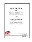
1
SSC-303-F- (303-FS) OR BLC-303-F (303-F)-650-521-CAC6.00-ISSUE4.0 SERVICE MANUAL FOR MODEL SSC-303-F (FORMERLY 303-FS) OR MODEL BLC-303-F (FORMERLY 303-F) CHARGE-A-CALL TELEPHONE EQUIPPED WITH CAC6.00 FIRMWARE Serving the Telephone Industry Since 1930 Communication Equipment & Engineering Company 1580 NW 65th Avenue Plantation, FL 33313 Voice: 954-587-5430 Fax: 954-587-5440 ISSUE 4.0 IMPORTANT INFORMATION FOR CUSTOMER Please fill in before you continue. The following information is necessary when calling CEECO for assistance. MODEL NUMBER MODEL SSC-303-F EQUIPPED WITH CAC6.00 FIRMWARE SERIAL NUMBER DATE MANUFACTURED LOCATION INSTALLED For us to better serve you, please have this information available when calling for technical support. CEECO Communication Equipment & Engineering Company 1580 NW 65th Avenue Plantation, FL 33313 (954) 587-5430 Voice (954) 587-5440 Fax CEECO Communication Equipment & Engineering Company PROPRIETARY 2 ISSUE 4.0 TABLE OF CONTENTS SECTION PAGE 1.0 INTRODUCTION................................................................................................... 4 2.0 GENERAL ............................................................................................................... 4 3.0 PROGRAMMING .................................................................................................. 5 PROGRAMMING CONTINUED… ..................................................................... 6 PROGRAMMING CONTINUED… ..................................................................... 7 PROGRAMMING CONTINUED… ..................................................................... 8 PROGRAMMING CONTINUED… ..................................................................... 9 PROGRAMMING CONTINUED… ................................................................... 10 4.0 TESTING/OPERATION ..................................................................................... 11 TESTING/OPERATION CONTINUED… ........................................................ 12 5.0 RECOMMENDED TOOLS AND TEST EQUIPMENT .................................. 12 6.0 INSTALLATION NOTES AND ASSEMBLY INSTRUCTIONS ................... 13 7.0 SPECIFICATIONS............................................................................................... 14 8.0 PARTS LIST ......................................................................................................... 15 9.0 FCC NOTICE........................................................................................................ 16 10.0 REPAIR AND RETURN INFORMATION ....................................................... 17 11.0 WARRANTY POLICY ........................................................................................ 18 12.0 DIAGRAM............................................................................................................. 19 CEECO Communication Equipment & Engineering Company PROPRIETARY 3 ISSUE 4.0 1.0 INTRODUCTION The practices in this manual provide installation and maintenance information for the Model SSC-303-F Stainless Steel Wall Telephone, equipped with CAC6.00 software. For information not included in this manual, please call or write: CEECO Customer Service 1580 NW 65th Avenue Plantation, FL 33313 (954) 587-5430 2.0 GENERAL The CEECO Model SSC-303-F Telephone, equipped with CAC6.00 Firmware, is a stainless steel; microprocessor-based coinless wall phone designed to withstand abuse and fraudulent call attempts. The phone may be programmed to: implement call restrictions allow incoming calls select the width of the dial tone detection window mute the microphone to guard against fraud select tone (DTMF) or pulse dialing automatically time and disconnect a phone call speed-dial numbers Automatically dial one or two numbers (typically access numbers) when the handset is lifted. As you can see, this telephone has a number of useful features and you may use any or all of them. Attempts to hookswitch dial will cause the microprocessor to go "on hook" until the attempt has ended. The steel housing and chrome plated tone dial are vandal resistant. An armored cord, hearing aid compatible handset is standard. CEECO Communication Equipment & Engineering Company PROPRIETARY 4 ISSUE 4.0 3.0 PROGRAMMING 3.1 Connect the telephone to a working telephone line or a DTMF test set. 3.2 Locate the two plastic mini-jumpers on the edge of the printed circuit board and move them to the “ON” position, as depicted on the last page of this manual. 3.3 Lift the handset and wait for dial tone before beginning programming. First read through the programming section and then do the actual programming as you read along again. Programming is accomplished by way of the DTMF keypad. The programming can be accomplished in one continuous sequence without having to stop or perform any measures between programming sections. It is important to be slow and deliberate when pressing the keys during programming. A missed or partial tone will result in improper programming. 3.4 Utilizing the keypad, enter # 9 7. This will clear all memory locations. 3.5 Enter # 0 0, which accesses the telephone options memory location. There are six (6) selections to be made in this location. By entering a selection into each of the six programming digit locations, the phone is customized for the particular installation. You must make an entry for each of the six digit locations. The six digit locations and the available selections are shown on the next page. Compare the example below to the information on the next page and then enter the 6 numbers you choose. Example: Entering #00 followed by 101003 would program the phone to have no call restrictions, no incoming call allowed, a wide dial tone detect window, a muted microphone initially, DTMF dialing, and a 5 minute automatic timed call disconnect. CEECO Communication Equipment & Engineering Company PROPRIETARY 5 ISSUE 4.0 PROGRAMMING CONTINUED… Location #00: Digit 1 0 1 Implement Call restrictions No call restrictions Digit 2 0 1 No incoming calls allowed Incoming calls allowed Digit 3 0 1 Narrow dial tone detect window Wide dial tone detect window (Always recommended) Digit 4 0 1 Mute the microphone until the user dials a digit Unmute the microphone after the access number is dialed Digit 5 0 1 2 DTMF dialing 10 PPS pulse dialing 20 PPS pulse dialing Digit 6 0=no call timeout 1=2 min.call timeout 2=3 min.call timeout 3=5 min.call timeout 4=10 min. call timeout 5=12 min.call timeout 6=15 min.call timeout 7=20 min.call timeout 8=25 min.call timeout 9=30 min.call timeout Be sure to record your selections in the table below for future reference. Telephone Options Table: #00 __ __ __ __ __ __ 1 2 3 4 5 6 CEECO Communication Equipment & Engineering Company PROPRIETARY 6 ISSUE 4.0 PROGRAMMING CONTINUED… 3.6 If you desire the phone to automatically dial a number (up to eleven digits in length) when the handset is lifted, now is the time to enter it. If this is not a desired function, proceed to section 3.8. Programming location #19 stores the auto-dial number. Therefore, enter # 1 9 followed by the desired auto dial number. For example: Entering #199 will program the phone to automatically dial a 9, when the handset is lifted. Be sure to record your entry in the table below for future reference. 1st Auto Dial Number Table: #19 __ __ __ __ __ __ __ __ __ __ __ 3.7 If you desire the phone to automatically dial a second number (up to eleven digits in length) after the one stored in location #19 (see above), now is the time to enter it. If this is not a desired function, then proceed to section 3.8. Programming location #18 stores the second auto dial number. In order to use #18, you must first use #19. This number will dial out approximately one second after any number stored in the #19 location. Enter # 1 8 followed by the desired auto dial number. For example: Entering #1818005551212 will program the phone to dial 1800-555-1212 approximately one second after it dials the number stored in location #19. Combining the examples from this section and the one above, entering #199#1818005551212 will program the phone to automatically dial 9, pause one second and automatically dial 1-800-5551212, when the handset is lifted. Be sure to record your entry in the table below for future reference. 2nd Auto Dial Number Table: #18 __ __ __ __ __ __ __ __ __ __ __ CEECO Communication Equipment & Engineering Company PROPRIETARY 7 ISSUE 4.0 PROGRAMMING CONTINUED… 3.8 If you desire to have speed-dialing capability, now is the time to program it. If this is not a desired function, proceed to section 3.9. There are 40 speed-dial locations available. Those locations are #30 thru #69. The speed numbers may be up eleven digits in length. Simply enter the pound key, followed by the location number, followed by the desired speed dial number. 1 2 3 4 5 6 7 8 9 * 0 # CEECO Communication Equipment & Engineering Company PROPRIETARY 8 ISSUE 4.0 PROGRAMMING CONTINUED… You could feasibly program all forty locations in one continuous programming sequence. Example: Entering #305551212#315875430#325839907 will program the phone to automatically dial 555-1212 when #30 is dialed, 587-5430 when #31 is dialed, and 583-9907 when #32 is dialed. Please note that, when the phone is put into operation, the # key must be dialed preceding the two digit location number, in order to release the speed dial number. * Be sure to record your speed dial entries in the table below for future reference: Speed Dial Table: #30 __ #31 __ #32 __ #33 __ #34 __ #35 __ #36 __ #37 __ #38 __ #39 __ #40 __ #41 __ #42 __ #43 __ #44 __ #45 __ #46 __ #47 __ #48 __ #49 __ __ __ __ __ __ __ __ __ __ __ __ __ __ __ __ __ __ __ __ __ __ __ __ __ __ __ __ __ __ __ __ __ __ __ __ __ __ __ __ __ __ __ __ __ __ __ __ __ __ __ __ __ __ __ __ __ __ __ __ __ __ __ __ __ __ __ __ __ __ __ __ __ __ __ __ __ __ __ __ __ __ __ __ __ __ __ __ __ __ __ __ __ __ __ __ __ __ __ __ __ __ __ __ __ __ __ __ __ __ __ __ __ __ __ __ __ __ __ __ __ __ __ __ __ __ __ __ __ __ __ __ __ __ __ __ __ __ __ __ __ __ __ __ __ __ __ __ __ __ __ __ __ __ __ __ __ __ __ __ __ __ __ __ __ __ __ __ __ __ __ __ __ __ __ __ __ __ __ __ __ __ __ __ __ __ __ __ __ __ __ __ __ __ __ __ __ __ __ __ __ #50 __ #51 __ #52 __ #53 __ #54 __ #55 __ #56 __ #57 __ #58 __ #59 __ #60 __ #61 __ #62 __ #63 __ #64 __ #65 __ #66 __ #67 __ #68 __ #69 __ __ __ __ __ __ __ __ __ __ __ __ __ __ __ __ __ __ __ __ __ __ __ __ __ __ __ __ __ __ __ __ __ __ __ __ __ __ __ __ __ __ __ __ __ __ __ __ __ __ __ __ __ __ __ __ __ __ __ __ __ CEECO Communication Equipment & Engineering Company PROPRIETARY __ __ __ __ __ __ __ __ __ __ __ __ __ __ __ __ __ __ __ __ __ __ __ __ __ __ __ __ __ __ __ __ __ __ __ __ __ __ __ __ __ __ __ __ __ __ __ __ __ __ __ __ __ __ __ __ __ __ __ __ __ __ __ __ __ __ __ __ __ __ __ __ __ __ __ __ __ __ __ __ __ __ __ __ __ __ __ __ __ __ __ __ __ __ __ __ __ __ __ __ __ __ __ __ __ __ __ __ __ __ __ __ __ __ __ __ __ __ __ __ __ __ __ __ __ __ __ __ __ __ __ __ __ __ __ __ __ __ __ __ 9 ISSUE 4.0 PROGRAMMING CONTINUED… 3.9 If you desire the phone to implement call restrictions, we will program the restrictions now. If this is not a desired function, proceed to section 3.10. In order for the phone to implement restrictions, a “0” must have been selected for Digit 1 under programming location #00. If this was not done, repeat section 3.5 in its entirety. The associated programming locations are #70 thru #89. Each of these twenty (20) locations may be used to program one call restriction. Each location will store a number (pattern) of up to eleven (11) digits in length. An “*” represents a wild card, so any time you enter the “*” key, you tell the phone to allow any single digit in its place. In order to restrict calling patterns, you program the phone to tell it which patterns to allow. In turn, it will block all others. Take a moment to look over the examples below. When you are finished, enter the # key, followed by a location code, followed by the desired number/pattern. EXAMPLE: Entering #700********** allows all 0+ and 0- calls. Entering #71911 allows 911 to be dialed. Entering #721800******* allows any 1-800 call. Entering #73******* allows 7-digit calls. Entering #74587**** allows 7-digit calls beginning with 587. Each pattern that you program will be “allowed” by the phone. If call restrictions are implemented (Location #00 Digit 1), the phone will only permit the calls that it is specifically programmed to allow. Any numbers that have been programmed into the speed, #19 or #18 locations do not have to be programmed again under this section. 3.10 Programming is now completed. Hang up the phone and return the minijumpers to the “OFF” position, as depicted on the last page of this manual. The phone is now ready for Testing/Operation. CEECO Communication Equipment & Engineering Company PROPRIETARY 10 ISSUE 4.0 4.0 TESTING/OPERATION 4.1 With the phone connected to the DTMF test set or working telephone line, lift the handset. Any number that was programmed into Location #19 should automatically dial out, at this time. If not, hang up the phone and repeat sections 3.2, 3.3, 3.6, and 3.10 only. If this does not solve the problem, please refer to section 10.2. 4.2 If any number was programmed into Location #18, that number should automatically dial out approximately one second after the number stored in Location #19 dials out. If not, hang up the phone and repeat sections 3.2, 3.3, 3.7, and 3.10 only. If this does not solve the problem, please refer to section 10.2. Please note that, in order to use Location #18, Location #19 must first be used. 4.3 If Locations #19 and/or #18 have not been programmed, you should receive dial tone on the line. 4.4 If you programmed speed-dial numbers, try them now. When you press the # key followed by the two-digit location code, any number stored in that location should be released. For example, entering #30 should cause the phone to automatically dial any number stored in Location #30. If not, hang up the phone and repeat sections 3.2, 3.3, 3.8, and 3.10 only. It is not necessary to try to reprogram all of the speed dial locations, but only the ones that are not working. If this does not solve the problem, please refer to section 10.2. 4.5 If you opted to use phone implemented call restrictions, try some of them now. The phone should only permit “allowed” calls to be dialed. When you try to dial a number that you did not “allow”, the phone should sound an error tone (three short beeps) and reset the line. If not, hang up and repeat sections 3.2, 3.3, 3.5, 3.9, and 3.10 only. If this does not solve the problem, please refer to section 10.2. CEECO Communication Equipment & Engineering Company PROPRIETARY 11 ISSUE 4.0 TESTING/OPERATION CONTINUED… 5.0 4.6 Try placing a call to the phone. If the phone was programmed to accept incoming calls, it should ring and be answered with normal phone operation to follow. If it was programmed not to accept incoming calls, it will still ring, but when it is answered the called party will not be heard on the far end. The microphone will be muted. The Phone will then sound an error tone after approximately four seconds and reset itself. If this does not solve the problem, please refer to section 10.2. 4.7 If the phone was programmed to automatically time and disconnect the phone call (Call timeout feature), try making a telephone call. Time the call and see if the phone, in fact, automatically disconnects after the programmed time period. Please keep in mind that this will not be exact. If this fails, hang up and repeat sections 3.2, 3.3, 3.5, and 3.10 only. If this does not solve the problem, please refer to section 10.2. 4.8 Also be sure to determine that the microphone is muting as it was programmed (Location #00) and that the phone is in either DTMF (tone) dialing mode or pulse dialing mode as programmed (Also Location #00). DTMF sounds like definite tones or beeps, whereas pulse-dialing sounds like rhythmic clicks. If the phone does not seem to be functioning as programmed, hang up and repeat sections 3.2, 3.3, 3.5, and 3.10 only. If this does not solve the problem, please refer to section 10.2. 4.9 Attempt to “hookswitch dial” by tapping quickly on the tongue of the hookswitch assembly. The phone should momentarily open the line, until the attempt is over, and then return dial tone. If not, please refer to section 10.2. RECOMMENDED TOOLS AND TEST EQUIPMENT DTMF Test Set Volt/Ohm Meter 1/4" Nut Driver Flat Blade Screw Driver Security Tool, CEECO Part Number 301-037 CEECO Communication Equipment & Engineering Company PROPRIETARY 12 ISSUE 4.0 6.0 INSTALLATION NOTES AND ASSEMBLY INSTRUCTIONS 6.1 Using a 301-037 security tool (sold separately), loosen and remove the security screw. 6.2 The security tool is for a standard 5/32" button head screw generally used on the framework of the phone booths. 6.3 Separate the cover assembly from the backplate assembly. 6.4 The backplate assembly may be installed on any standard backboard. 6.5 Run the inside station wire through the backplate assembly and terminate on the RJ11C terminal block on the backplate. 6.6 The use of a gas tube station protector is recommended. The station ground should not exceed 50 ohms. 6.7 Plug the modular line cord from the cover assembly into the RJ11C terminal block. 6.8 Dress the line cable away from the security screw and install the cover assembly by inserting the tabs into the slots on top of the backplate. 6.9 Secure the cover assembly by tightening the security screw. *****WARNING***** A. Never install telephone wiring during a lightning storm. B. Never install telephone jacks in wet locations unless the jack is specifically designed for wet locations. C. Never touch uninsulated telephone wires or terminals unless the telephone line has been disconnected at the network interface. D. Use caution when installing or modifying telephone lines. CEECO Communication Equipment & Engineering Company PROPRIETARY 13 ISSUE 4.0 7.0 SPECIFICATIONS INPUT POWER: C.O. Line powered LOOP CURRENT: 23ma. min. 80ma. max.(48 VOLT LOOP) IMPEDANCE: 600 ohms SIGNALING: DTMF, 70ms tone, 50ms spacing OUTPUT: -8.0 to -10.0dbm HEARING AID COMPATIBLE: Meets EIA standards ENVIRONMENTAL: Temperature 0C to 50C Humidity 20%-90% non-condensating PROGRAMMING: Via DTMF keypad. TELEPHONE PANEL: 16 ga Stainless Steel DIMENSIONS: 7 1/2" Wide x 21" High x 6 1/2" Deep (Handset on hook) MOUNTING: Standard Coinless Public Telephone footprint MEMORY RETENTION: Lithium Battery - Long Life WEIGHT: Approximately 17 Pounds FCC REGISTRATION: BW88T7-13823-TE-T UL LISTED NO.: 6OF5 RINGER EQUIVALENCY: 0.4A TYPE JACK: RJ11C FIRMWARE: CAC6.00 CEECO Communication Equipment & Engineering Company PROPRIETARY 14 ISSUE 4.0 8.0 PARTS LIST QUANTITY PART NUMBER DESCRIPTION 1 301-030 Instruction Card Kit 1 301-106-29 Armored Cord Handset 1 301-006 Ringer 1 301-009 Network 1 301-012 Outer Cover Locking Screw 1 301-581 Tongue & Bracket Assembly 1 301-588 Hookswitch Cradle 2 301-570 Microswitch Assembly 1 301-018 Modular Line Cord 1 301-039 Number Window 1 301-040 Number Card 1 301-051 Backplate 1 301-054 Modular Connector (RJ11C) 1 700-008 Keypad Cable 1 650-570 Network Cable 1 650-521 MCRK-2 Board 1 705-110 Connectorized Keypad W/ 705 Mounting 2 9023 Security Screws 301-037 Security Tool ACCESSORIES: 1 CEECO Communication Equipment & Engineering Company PROPRIETARY 15 ISSUE 4.0 9.0 FCC NOTICE 9.1 FCC REGISTRATION AND REPAIR INFORMATION Your new telephone has been registered with the Federal Communication Commission (FCC) in accordance with Part 68 of its rules. The FCC requires that you be advised of certain requirements involving the use of this telephone. 9.2 CONNECTION WITH THE NATIONWIDE TELEPHONE NETWORK The FCC requires that you connect this telephone to the Nationwide Telephone Network through a registered jack provided by the Telephone Company in your area. This jack is a modular outlet, which you can order from your local telephone company. 9.3 NOTIFICATION TO THE TELEPHONE COMPANY Before connecting this telephone, the FCC requires that you notify your local telephone company business office. The number is in the front of your phone book. Tell them: The "line" to which you will connect the telephone (that is, your phone number) and the telephone's FCC registration number and ringer equivalence number. These numbers are listed in Section 9.0. The FCC further requires that you notify your local telephone company when permanently disconnecting this telephone. CEECO Communication Equipment & Engineering Company PROPRIETARY 16 ISSUE 4.0 10.0 REPAIR AND RETURN INFORMATION 10.1 WARRANTY REPAIR Any device returned requiring warranty service, repair or credit must be accompanied with a "Return Material Authorization" (RMA) form. It must include: return shipping instructions, original purchase order number and special marking instruction. A description of the trouble observed must be attached to the defective unit. This information must be inside the shipping container. 10.2 DIRECT ALL INQUIRES TO: CEECO Repair Department 1580 NW 65th Avenue Plantation, FL 33313 (954) 587-5430 10.3 NON-WARRANTY REPAIR CEECO will repair equipment out of warranty for a set charge plus parts. The customer must pay the shipping costs both directions. 10.4 RETURN FOR CREDIT Material may be returned for credit only with prior approval. Material authorized for return is subject to a 15% restocking charge based on the manufacturer's list price. Return RMA must be requested no later than 60 days after original shipment. CEECO Communication Equipment & Engineering Company PROPRIETARY 17 ISSUE 4.0 11.0 WARRANTY POLICY 11.1 GENERAL CEECO products are guaranteed to be free of defects in material and workmanship for a period of 365 days from the date of original purchase. CEECO's obligation under this warranty is limited to repair or replacement of any part found to be defective by CEECO. Under no circumstances shall CEECO be liable for loss, damage, cost of repair or consequential damages of any kind, which have been caused by neglect, abuse, act of God or improper operation of equipment. This warranty is limited to the value of material only. 11.2 PRINTED CIRCUIT BOARDS Printed circuit boards should not be repaired in the field. If a unit is found to be faulty, replace it with another unit and return the faulty unit to CEECO for repair. Modifications by any one other than CEECO will void the warranty. CEECO Communication Equipment & Engineering Company PROPRIETARY 18 ISSUE 4.0 12.0 DIAGRAM Locate the mini jumpers on the corner of the PCB. O N O MOVE THE MINI JUMPERS TO THE ON POSITION BEFORE GOING OFFHOOK. When programming is completed, move the mini jumpers to the OFF position. O FF N O O FF N O FF NOTE: Do not leave the mini jumpers in the ON position; this will decrease battery life. CEECO Communication Equipment & Engineering Company PROPRIETARY 19