1
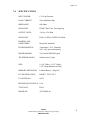
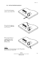
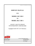
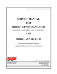
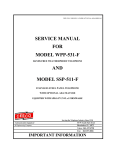
SSP-363-E4-(SSP-365-E-4)-AUTODIAL48-ISSUE4.0
SERVICE MANUAL
FOR
MODEL SSP-363-E4
(FORMERLY SSP-365-E-4)
STAINLESS STEEL PANEL TELEPHONE
EQUIPPED WITH AUTODIAL48 FIRMWARE
Serving the Telephone Industry Since 1930
Communication Equipment
& Engineering Company
519 W South Park Street
Okeechobee, FL 34972
Voice: 863-357-0798
Fax: 863-357-0006
ISSUE 4.0
IMPORTANT INFORMATION
FOR
CUSTOMER
Please fill in before you continue.
The following information is necessary when calling CEECO for assistance.
MODEL NUMBER
MODEL SSP-363-E4 EQUIPPED WITH
AUTODIAL48 FIRMWARE
SERIAL NUMBER
DATE MANUFACTURED
LOCATION INSTALLED
For us to better serve you, please have this information available when calling for
technical support.
CEECO
Communication Equipment & Engineering Company
519 W South Park Street
Okeechobee, FL 34972
863-357-0798- telephone
863-357-0006- facsimile
[email protected]
www.ceeco.net
CEECO
Communication Equipment & Engineering Company
PROPRIETARY
2
ISSUE 4.0
TABLE OF CONTENTS
SECTION
PAGE
1.0
INTRODUCTION................................................................................................... 4
2.0
GENERAL............................................................................................................... 4
3.0
PROGRAMMING .................................................................................................. 5
PROGRAMMING CONTINUED…..................................................................... 6
4.0
TESTING................................................................................................................. 6
5.0
RECOMMENDED TOOLS AND TEST EQUIPMENT .................................... 8
6.0
INSTALLATION INSTRUCTIONS .................................................................... 8
7.0
SPECIFICATIONS................................................................................................. 9
8.0
PARTS LIST ......................................................................................................... 10
9.0
FCC NOTICE........................................................................................................ 11
10.0 REPAIR & RETURN POLICY .......................................................................... 12
11.0 WARRANTY POLICY ........................................................................................ 13
12.0 MINI-JUMPER DIAGRAM................................................................................ 14
CEECO
Communication Equipment & Engineering Company
PROPRIETARY
3
ISSUE 4.0
1.0
INTRODUCTION
The practices in this manual provide installation, programming and maintenance
information for CEECO Model SSP-363-E4 Stainless Steel Panel Telephone,
equipped with version AUTODIAL48 firmware.
The information in this manual is subject to change without notification.
For information not included in this manual, please call or write:
CEECO
Customer Service
519 W South Park Street
Okeechobee, FL 34972
863-357-0798- telephone
863-357-0006- facsimile
[email protected]
www.ceeco.net
2.0
GENERAL
2.1
The CEECO Model SSP-363-E4 Stainless Steel Panel Telephone is a
microprocessor-based telephone designed to deter fraud from hand-held
tone dialers and hookswitch dialing. The microprocessor keeps the
transmitter muted (off) during periods of dial tone to guard against the use
of hand-held dialers. Attempts to dial a number by tapping the
hookswitch will cause the microprocessor to "reset" and open the line,
thereby avoiding fraudulent call attempts.
2.2
One of forty-eight (48) pre-programmed numbers may be speed dialed, by
pressing one key on the Single Button Access (SBA) panel, located on the
front of the telephone. The panel consists of four keypads grouped
together to form the forty-eight (48) speed dial keys. Each of the keys
may be used to speed dial one number of up to twelve (12) digits in length.
2.3
Programming is accomplished via the top left, 12-button, SBA keypad.
The top left keypad is used to program the speed dial numbers for all
forty-eight (48) keys.
2.4
The phone may be programmed to allow or block incoming calls.
CEECO
Communication Equipment & Engineering Company
PROPRIETARY
4
ISSUE 4.0
3.0
PROGRAMMING
THIS EQUIPMENT IS TELEPHONE LINE POWERED. DURING PROGRAMMING THE CENTRAL OFFICE OR PBX
MAY RESPOND TO THE PROGRAMMING CODES WITH VARIOUS BUSY TONE, REORDER TONE, RECORDINGS,
ETC. THESE TONES AND RECORDINGS WILL HAVE NO EFFECT ON THE PROGRAMMING. PLEASE IGNORE
THEM.
3.1
Utilizing the security tool (P/N 301-037 sold separately) remove the
telephone from its housing/mounting. Connect the Telephone line cord
to a working telephone line or a DTMF test set.
3.2
Looking at the rear of the telephone, locate the two plastic mini-jumpers
on the Printed Circuit Board. Move them to the “ON” position as
depicted in the diagram on the last page of this manual.
3.3
Now, looking at the front of the phone, observe four keypads (2 x 6 keys
each) grouped together. The top left keypad is used for all programming.
Please refer to the keypad configuration diagram on page 7. The
corresponding digits for the top left programming keypad are illustrated on
the keys themselves. The corresponding programming locations for all
forty-eight (48) keys are indicated to the right of each key. It is important
to be slow and deliberate when pressing the keys during programming. A
missed or partial tone could result in improper programming.
3.4
Lift the handset and wait for dial tone to begin programming. Utilizing
the top left keypad, enter # 9 7. This will clear all programmable
memory locations to begin the programming sequence.
3.5
Enter # 0 0, followed by 0 1 1(to allow incoming calls) or 0 0 1(to block
incoming calls. For example: Entering #00011 will program the phone to
permit incoming calls, and conversely entering #00001 will program the
phone to block incoming calls. One of these choices must be programmed
into the phone in order for the phone to operate properly.
3.6
Each of the forty-eight (48) keys on the front of the telephone has its own
speed dial programming location (#01 thru #48). Each location will
store a number of up to twelve (12) digits in length. The diagram on page
7 depicts the correlation between the keys and the programming locations.
The corresponding programming locations appear to the right of the keys.
Utilizing the top left programming keypad, enter the programming
location of the desired key, followed by the desired speed dial number
for that particular key. For example: Enter #015551212. When in
operation, this will cause the phone to automatically dial the number 5551212, when the very top left key is pressed. All forty-eight (48) keys may
be programmed in this manner (i.e.#015551212#025875430#03911
#045875440#055617878#064219090…).
CEECO
Communication Equipment & Engineering Company
PROPRIETARY
5
ISSUE 4.0
PROGRAMMING CONTINUED…
It is recommended that only six (6) keys receive programming at one
time. Those six keys should then be tested to ensure proper programming,
before continuing on. To test them, hang up the phone and return the two
plastic mini jumpers to the “OFF” position, as depicted on the last page of
this manual. Then lift the handset, wait for dial tone, and press one of the
programmed keys. The programmed number should automatically dial
out. If not, try programming the failed key(s) again. Do this for each of
the keys. Once programming of those keys is successful, proceed with
the next group of keys. Remember to move the mini-jumpers to the
“ON” position to program and the “OFF” position to test. Overall, this is
the best approach toward achieving proper programming without
unnecessary wasted time.
3.7
4.0
When programming has been completed, hang up the phone. Return the
two plastic mini-jumpers to the “OFF” position, as depicted on the last
page of this diagram.
TESTING
4.1
Lift the handset and wait for dial tone. This may take a second or two.
The handset transmitter will be muted.
4.2
Press one of the forty-eight (48) keys, which has been preprogrammed
with a speed dial number. The programmed number will speed dialed out.
The handset transmitter will then be enabled. Normal phone operation
should follow.
4.3
Keep the telephone off hook and allow the called party to hang up first.
Wait for the Central Office Equipment or PBX to time out and return dial
tone.
4.4
As soon as dial tone is received, three (3) tones will be heard. The phone
will momentarily open the line. The phone will then reset for another call.
The handset transmitter will be disabled.
4.5
Place a call into the telephone. If incoming calls are not allowed, the
handset transmitter will not turn on. If incoming calls are allowed, the
transmitter will turn on approximately three (3) seconds after the incoming
call is answered.
4.8
Attempt to "Hookswitch Dial" by tapping quickly on the hookswitch. The
telephone should hang up, re-seize the telephone line and return dial tone.
CEECO
Communication Equipment & Engineering Company
PROPRIETARY
6
ISSUE 4.0
KEYPAD LAYOUT DIAGRAM…
PROGRAMMING KEYPAD TOP LEFT
PROGRAMMING LOCATIONS
APPEAR TO RIGHT OF KEYS
#01
#13
#25
#37
#02
#14
#26
#38
#03
#15
#27
#39
#04
#16
#28
#40
#05
#17
#29
#41
#06
#18
#30
#42
#07
#19
#31
#43
#08
#20
#32
#44
#09
#21
#33
#45
#10
#22
#34
#46
#11
#23
#35
#47
#12
#24
#36
#48
CEECO
Communication Equipment & Engineering Company
PROPRIETARY
7
ISSUE 4.0
5.0
RECOMMENDED TOOLS AND TEST EQUIPMENT
Volt Meter
1/4" Nut Driver
Flat Blade Screw Driver
Security Tool P/N 301-037
6.0
INSTALLATION INSTRUCTIONS
6.1
Using a 301-037 security tool (sold separately), loosen and remove the
security screws.
6.2
The security tool is for a standard 5/32" button head screw generally used
on the framework of the phone booths.
6.3
The station ground should not exceed 50 ohms.
6.4
Run the inside station wire and terminate onto the RJ11C terminal block.
6.5
Plug the modular line cord from the telephone assembly into the RJ11C
terminal block.
6.6
Dress the line cable away from the security screws and install the cover
assembly.
6.7
Secure the cover assembly by tightening the security screws.
*****WARNING*****
A.
Never install telephone wiring during a lightening storm.
B.
Never install telephone jacks in wet locations unless the jack
is specifically designed for wet locations.
C.
Never touch uninsulated telephone wires or terminals unless
the telephone line has been disconnected at the network
interface.
D.
Use caution when installing or modifying telephone lines.
CEECO
Communication Equipment & Engineering Company
PROPRIETARY
8
ISSUE 4.0
7.0
SPECIFICATIONS
INPUT POWER:
C.O. Line Powered
LOOP CURRENT:
23ma Min 80ma Max
IMPEDANCE:
600 Ohms
SIGNALING:
DTMF-70ms Tone, 50ms Spacing
OUTPUT LEVEL:
-10.0 to -12.0 dBm
SIGNALING:
Pulses 10 PPS or 20 PPS 50% Break
HEARING AID
COMPATIBLE:
Meets EIA Standards
ENVIRONMENTAL:
Temperature- 50°C, Humidity
20% - 90% non-condensating
PROGRAMMING:
Via External DTMF Keypad
TELEPHONE PANEL:
Stainless Steel (14ga)
SIZE:
14 1/4" Wide x 12 1/2" High x
2 3/4" Deep (Handset on hook)
MEMORY RETENTION:
Lithium Battery - (long life)
FCC REGISTRATION:
BW88T7-13823-TE-T
UL LISTED NO.:
6OF5
RINGER EQUIVALENCE: 0.4A
TYPE JACK:
RJ11C
PROGRAM:
AUTODIAL48
CEECO
Communication Equipment & Engineering Company
PROPRIETARY
9
ISSUE 4.0
8.0
PARTS LIST
QUANTITY PART NUMBER
DESCRIPTION
1
301-018
Modular Cord
1
365-E-4
Telephone Panel
1
301-004
Handset
1
301-588
Hookswitch Cradle
1
301-581
Tongue and Bracket
2
301-570
Microswitch
4
306-105
SBA Panel
4
700-008
SBA Cable
1
301-009
Network
1
650-520
MCRK - 2 PC Board
(Modified)
1
301-054
Modular Jack
6
301-012
Security Screws
4
12029
Single Button Access (SBA) Keypad
ACCESSORIES:
1
700-008
Keypad Cable
1
301-037
Security Tool
1
401-009
Ringer
CEECO
Communication Equipment & Engineering Company
PROPRIETARY
10
ISSUE 4.0
9.0
FCC NOTICE
9.1
FCC REGISTRATION AND REPAIR INFORMATION
Your new telephone has been registered with the Federal Communication
Commission (FCC) in accordance with Part 68. The FCC requires that
you be advised of certain requirements involving the use of this telephone.
9.2
CONNECTION WITH THE NATIONWIDE TELEPHONE NETWORK
The FCC requires that you connect this telephone to the Nationwide
Telephone Network through a registered jack provided by the Telephone
Company in your area. This jack is a modular outlet, which you can order
from your local telephone company.
9.3
NOTIFICATION TO THE TELEPHONE COMPANY
Before connecting this telephone, the FCC requires that you notify your
local telephone company business office. The number is in the front of
your phone book.
Tell them:
The "line" to which you will connect the telephone (that is, your phone
number) and the telephone's FCC registration number and ringer
equivalence number. These numbers are listed in section 9.00.
The FCC further requires that you notify your local telephone company
when permanently disconnecting this telephone.
CEECO
Communication Equipment & Engineering Company
PROPRIETARY
11
ISSUE 4.0
10.0 REPAIR & RETURN POLICY
10.1
WARRANTY REPAIR
Any device returned requiring warranty service, repair or credit must be
accompanied with a "Return Material Authorization (RMA) Number” and
must also include: return shipping instructions, original purchase order
number and special marking instructions. A description of the trouble
observed must be attached to the defective unit. This information must be
inside the shipping container.
10.2
DIRECT ALL INQUIRES TO:
CEECO
Repair Department
863-357-0798- telephone
863-357-0006- facsimile
[email protected]
www.ceeco.net
10.3
NON-WARRANTY REPAIR
CEECO will repair equipment out of warranty for a set charge plus parts.
The customer must pay the shipping costs both directions.
10.4
RETURN FOR CREDIT
Material may be returned for credit only with prior approval. Material
authorized for return is subject to a 20% restocking charge based on the
manufacturer’s list price. Return Material Authorization must be
requested no later than 30 days after original shipment.
CEECO
Communication Equipment & Engineering Company
PROPRIETARY
12
ISSUE 4.0
11.0 WARRANTY POLICY
11.1
GENERAL
CEECO products are guaranteed to be free of defects in material and
workmanship for a period of 365 days from the date of original shipment.
CEECO’s obligation under this warranty is limited to repair or
replacement of any part found to be defective by CEECO. Under no
circumstances shall CEECO be liable for loss, damage, cost of repair or
consequential damages of any kind, which have been caused by neglect,
abuse, acts of God or improper operation of equipment.
CEECO will repair or replace any unit during this period if found to be
defective for reasons other than abuse and improper use or improper
installation. It is the buyer’s responsibility to return the defective unit to
the factory. CEECO will then repair or replace any defective parts and
return them to the buyer free of charge.
11.2
PRINTED CIRCUIT BOARDS
Printed circuit boards should not be repaired in the field. If a unit is found
to be faulty, replace it with another unit and return the faulty unit to
CEECO for repair. Modifications by anyone other than CEECO will void
the warranty.
CEECO
Communication Equipment & Engineering Company
PROPRIETARY
13
ISSUE 4.0
12.0 MINI-JUMPER DIAGRAM
Locate the mini jumpers
on the corner of the PCB.
ON
F
OF
MOVE THE MINI JUMPERS TO
THE ON POSITION BEFORE
GOING OFF-HOOK.
ON
F
OF
When programming is
completed, move the
mini- jumpers to the
OFF position.
ON
F
OF
NOTE:
Do not leave the mini-jumpers in the ON position;
this will decrease battery life.
CEECO
Communication Equipment & Engineering Company
PROPRIETARY
14