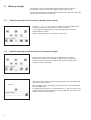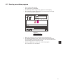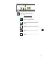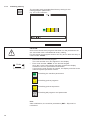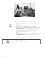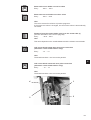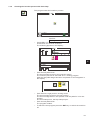
1
Manual, complete
745 - 34 - 2
Sewing unit for runstitching of piped flap
and welt pocket openings and pocket corners
Working methods: A, B, D, F
Operating Instructions
1
Installation Instructions
2
Service Instructions
3
Instructions for Programming DAC
4
Postfach 17 03 51, D-33703 Bielefeld • Potsdamer Straße 190, D-33719 Bielefeld
Telefon + 49 (0) 5 21 / 9 25-00 • Telefax + 49 (0) 5 21 / 9 25 24 35 • www.duerkopp-adler.com
Ausgabe / Edition:
08/2007
Änderungsindex
Rev. index: 01.0
Printed in Federal Republic of Germany
Teile-Nr./Part.-No.:
0791 745181
745 - 34 - 2
Manual, complete
Contents
Operating Instructions
Installation Instructions
Service Instructions
Instructions for Programming DAC
Interconnection-diagram
9870 745154 B
9890 745002 B
Pneumatic circuit plan
9770 745005
All rights reserved.
Property of Dürkopp Adler AG and copyrighted. Reproduction or publication of the content in
any manner, even in extracts, without prior written permission of Dürkopp Adler AG, is
prohibited.
Copyright © Dürkopp Adler AG - 2007
Foreword
This instruction manual is intended to help the user to become familiar
with the machine and take advantage of its application possibilities in
accordance with the recommendations.
The instruction manual contains important information on how to
operate the machine securely, properly and economically. Observation
of the instructions eliminates danger, reduces costs for repair and
down-times, and increases the reliability and life of the machine.
The instruction manual is intended to complement existing national
accident prevention and environment protection regulations.
The instruction manual must always be available at the machine/sewing
unit.
The instruction manual must be read and applied by any person that is
authorized to work on the machine/sewing unit. This means:
–
–
–
Operation, including equipping, troubleshooting during the work
cycle, removing of fabric waste,
Service (maintenance, inspection, repair) and/or
Transport.
The user also has to assure that only authorized personnel work on the
machine.
The user is obliged to check the machine at least once per shift for
apparent damages and to immediatly report any changes (including the
performance in service), which impair the safety.
The user company must ensure that the machine is only operated in
perfect working order.
Never remove or disable any safety devices.
If safety devices need to be removed for equipping, repairing or
maintaining, the safety devices must be remounted directly after
completion of the maintenance and repair work.
Unauthorized modification of the machine rules out liability of the
manufacturer for damage resulting from this.
Observe all safety and danger recommendations on the machine/unit!
The yellow-and-black striped surfaces designate permanend danger
areas, eg danger of squashing, cutting, shearing or collision.
Besides the recommendations in this instruction manual also observe
the general safety and accident prevention regulations!
General safety instructions
The non-observance of the following safety instructions can cause
bodily injuries or damages to the machine.
1. The machine must only be commissioned in full knowledge of the
instruction book and operated by persons with appropriate training.
2. Before putting into service also read the safety rules and
instructions of the motor supplier.
3. The machine must be used only for the purpose intended. Use of
the machine without the safety devices is not permitted. Observe all
the relevant safety regulations.
4. When gauge parts are exchanged (e.g. needle, presser foot, needle
plate, feed dog and bobbin) when threading, when the workplace is
left, and during service work, the machine must be disconnected
from the mains by switching off the master switch or disconnecting
the mains plug.
5. Daily servicing work must be carried out only by appropriately
trained persons.
6. Repairs, conversion and special maintenance work must only be
carried out by technicians or persons with appropriate training.
7. For service or repair work on pneumatic systems, disconnect the
machine from the compressed air supply system (max. 7-10 bar).
Before disconnecting, reduce the pressure of the maintenance unit.
Exceptions to this are only adjustments and functions checks made
by appropriately trained technicians.
8. Work on the electrical equipment must be carried out only by
electricians or appropriately trained persons.
9. Work on parts and systems under electric current is not permitted,
except as specified in regulations DIN VDE 0105.
10. Conversion or changes to the machine must be authorized by us
and made only in adherence to all safety regulations.
11. For repairs, only replacement parts approved by us must be used.
12. Commissioning of the sewing head is prohibited until such time as
the entire sewing unit is found to comply with EC directives.
13. The line cord should be equipped with a country-specific mains
plug. This work must be carried out by appropriately trained
technicians (see paragraph 8).
It is absolutely necessary to respect the safety
instructions marked by these signs.
Danger of bodily injuries !
Please note also the general safety instructions.
Contents
page:
Part 4: Instructions for Programming DACIII, class 745-34-2
Program version A 01
1.
General . . . . . . . . . . . . . . . . . . . . . . . . . . . . . . . . . . . . . . . . . . . . . . . . . . .
3
2.
Operating terminal . . . . . . . . . . . . . . . . . . . . . . . . . . . . . . . . . . . . . . . . . . . .
4
3.
Selecting the language . . . . . . . . . . . . . . . . . . . . . . . . . . . . . . . . . . . . . . . . .
5
4.
4.1
4.2
Memory dongle
Transferring data from the memory dongle to the control. . . . . . . . . . . . . . . . . . . . . .
Transferring data from the control to the memory dongle. . . . . . . . . . . . . . . . . . . . . .
6
6
5.
5.1
5.2
Main operating screen
Sewing and test programs: menu structure . . . . . . . . . . . . . . . . . . . . . . . . . . . . . .
Changing parameter values . . . . . . . . . . . . . . . . . . . . . . . . . . . . . . . . . . . . . . .
8
9
6.
6.1
6.2
6.3
6.4
6.5
6.6
Sewing programs
Calling sewing-program parameter screens
Running a machine program . . . . . . . . . .
Main screen. . . . . . . . . . . . . . . . . . . .
Pocket programs . . . . . . . . . . . . . . . . .
Blower mode . . . . . . . . . . . . . . . . . . .
Pocket sequence . . . . . . . . . . . . . . . .
.
.
.
.
.
.
.
.
.
.
.
.
.
.
.
.
.
.
.
.
.
.
.
.
.
.
.
.
.
.
.
.
.
.
.
.
.
.
.
.
.
.
.
.
.
.
.
.
.
.
.
.
.
.
.
.
.
.
.
.
.
.
.
.
.
.
.
.
.
.
.
.
.
.
.
.
.
.
.
.
.
.
.
.
.
.
.
.
.
.
.
.
.
.
.
.
10
11
12
14
34
36
7.
7.1
7.2
7.3
7.3.1
7.3.2
7.3.3
7.3.4
7.3.4.1
7.3.4.2
7.3.4.3
7.3.4.4
7.3.4.5
7.3.5
7.3.5.1
7.3.5.2
7.3.5.3
7.3.5.4
7.3.5.5
Setting and test programs
Calling setting and test programs . . . . . . . . . . . . . . . . . . . . .
Machine parameters . . . . . . . . . . . . . . . . . . . . . . . . . . . .
Machine-specific setting and test programs . . . . . . . . . . . . . .
Adjusting the looper-thread monitor . . . . . . . . . . . . . . . . . . .
Initializing memory. . . . . . . . . . . . . . . . . . . . . . . . . . . . . .
Checking the smoother function . . . . . . . . . . . . . . . . . . . . .
Aligning the light barriers . . . . . . . . . . . . . . . . . . . . . . . . . .
Preparing the sewing unit and feed clamps . . . . . . . . . . . . . . .
Sewing unit with two light barriers for automatic angle recognition
Sewing unit with two light barriers, left or right flap positioning . . .
Sewing unit with one light barrier . . . . . . . . . . . . . . . . . . . . .
Error Display . . . . . . . . . . . . . . . . . . . . . . . . . . . . . . . . .
Checking the corner-blade settings . . . . . . . . . . . . . . . . . . .
Checking the corner-blade station . . . . . . . . . . . . . . . . . . . .
Checking the front left corner blade . . . . . . . . . . . . . . . . . . .
Checking the rear left corner blade . . . . . . . . . . . . . . . . . . . .
Checking corner-blade motion . . . . . . . . . . . . . . . . . . . . . .
Corner-blade machine parameters . . . . . . . . . . . . . . . . . . . .
.
.
.
.
.
.
.
.
.
.
.
.
.
.
.
.
.
.
.
.
.
.
.
.
.
.
.
.
.
.
.
.
.
.
.
.
.
.
.
.
.
.
.
.
.
.
.
.
.
.
.
.
.
.
.
.
.
.
.
.
.
.
.
.
.
.
.
.
.
.
.
.
.
.
.
.
.
.
.
.
.
.
.
.
.
.
.
.
.
.
.
.
.
.
.
.
.
.
.
.
.
.
.
.
.
.
.
.
.
.
.
.
.
.
.
.
.
.
.
.
.
.
.
.
.
.
.
.
.
.
.
.
.
.
.
.
.
.
.
.
.
.
.
.
.
.
.
.
.
.
.
.
.
.
.
.
.
.
.
.
.
.
.
.
.
.
.
.
.
.
.
.
.
.
.
.
.
.
.
.
.
.
.
.
.
.
.
.
.
.
.
.
.
.
.
.
.
.
.
.
.
.
.
.
.
.
.
.
.
.
.
.
.
.
.
.
.
.
.
.
.
.
.
.
.
.
.
.
.
.
.
.
.
.
.
.
.
.
.
.
.
.
.
.
.
.
.
.
.
.
.
.
.
.
.
.
.
.
.
.
.
.
.
.
.
.
.
.
.
.
38
40
46
47
48
49
50
51
53
55
57
58
59
60
60
60
61
62
.
.
.
.
.
.
.
.
.
.
.
.
.
.
.
.
.
.
.
.
.
.
.
.
.
.
.
.
.
.
.
.
.
.
.
.
.
.
.
.
.
.
.
.
.
.
.
.
.
.
.
.
.
.
.
.
.
.
.
.
.
.
.
.
.
.
.
.
.
.
.
.
.
.
.
.
.
.
4
Contents
page:
7.3.6
7.3.7
7.3.8
7.3.9
7.3.10
7.3.10.1
7.3.10.2
7.3.11
7.3.12
7.3.13
7.4
7.4.1
7.4.2
7.4.3
7.4.4
7.4.5
7.4.6
7.4.7
7.4.8
7.5
7.6
7.7
7.8
Testing needle and center-blade activation . . . . . . . . . .
Checking the tape feed . . . . . . . . . . . . . . . . . . . . . .
Checking the gripper folder without feed clamp (versions B
Checking the insertion process with feed clamp . . . . . . .
Checking and adjusting the piping knives . . . . . . . . . . .
Checking the piping knife motion . . . . . . . . . . . . . . . .
Setting the piping knife reference position . . . . . . . . . .
Step-by-step mode . . . . . . . . . . . . . . . . . . . . . . . .
Determining the cycle time . . . . . . . . . . . . . . . . . . . .
Dongle Menu . . . . . . . . . . . . . . . . . . . . . . . . . . . .
Multitest system . . . . . . . . . . . . . . . . . . . . . . . . . .
Displaying the program version and checksum. . . . . . . .
Testing RAM . . . . . . . . . . . . . . . . . . . . . . . . . . . .
Selecting input elements . . . . . . . . . . . . . . . . . . . . .
Checking input elements . . . . . . . . . . . . . . . . . . . . .
Selecting output elements . . . . . . . . . . . . . . . . . . . .
CAN test . . . . . . . . . . . . . . . . . . . . . . . . . . . . . . .
Checking the sewing drive . . . . . . . . . . . . . . . . . . . .
Error list . . . . . . . . . . . . . . . . . . . . . . . . . . . . . . .
Terminal self-test . . . . . . . . . . . . . . . . . . . . . . . . .
Display contrast value . . . . . . . . . . . . . . . . . . . . . .
Editing menus . . . . . . . . . . . . . . . . . . . . . . . . . . .
Adjusting the serial interface . . . . . . . . . . . . . . . . . .
. . . .
. . . .
and F
. . . .
. . . .
. . . .
. . . .
. . . .
. . . .
. . . .
. . . .
. . . .
. . . .
. . . .
. . . .
. . . .
. . . .
. . . .
. . . .
. . . .
. . . .
. . . .
. . . .
. . . .
. . . .
only).
. . . .
. . . .
. . . .
. . . .
. . . .
. . . .
. . . .
. . . .
. . . .
. . . .
. . . .
. . . .
. . . .
. . . .
. . . .
. . . .
. . . .
. . . .
. . . .
. . . .
.
.
.
.
.
.
.
.
.
.
.
.
.
.
.
.
.
.
.
.
.
.
.
.
.
.
.
.
.
.
.
.
.
.
.
.
.
.
.
.
.
.
.
.
.
.
.
.
.
.
.
.
.
.
.
.
.
.
.
.
.
.
.
.
.
.
.
.
.
.
.
.
.
.
.
.
.
.
.
.
.
.
.
.
.
.
.
.
.
.
.
.
.
.
.
.
.
.
.
.
.
.
.
.
.
.
.
.
.
.
.
.
.
.
.
.
.
.
.
.
.
.
.
.
.
.
.
.
.
.
.
.
.
.
.
.
.
.
.
.
.
.
.
.
.
.
.
.
.
.
.
.
.
.
.
.
.
.
.
.
.
.
.
.
.
.
.
.
.
.
.
.
.
.
.
.
.
.
.
.
.
.
.
.
.
.
.
.
.
.
.
.
.
.
.
.
.
.
.
.
.
.
.
.
.
.
.
.
.
.
.
.
.
.
.
.
.
.
.
.
.
.
.
.
.
.
.
.
.
.
.
.
.
.
.
.
.
.
.
.
.
.
.
.
.
.
.
.
.
.
.
.
.
.
.
.
.
.
.
.
.
.
.
.
.
.
.
.
.
.
.
.
.
.
.
.
64
65
66
67
68
68
69
70
71
71
72
73
74
75
77
78
81
82
83
84
85
86
87
8.
8.1
8.2
8.3
Error messages
Sewing motor controller error messages . . . . . . . . . . . . . . . . . . . . . . . . . . . . . . .
Stepping motor error messages . . . . . . . . . . . . . . . . . . . . . . . . . . . . . . . . . . . . .
Operating indicator error messages . . . . . . . . . . . . . . . . . . . . . . . . . . . . . . . . . .
88
89
89
1.
General
This manual contains important information on the safe and correct use
of the “DACIII” (Dürkopp Adler Control) new-generation controller.
Screen images in this brief description
The symbol display on the various screens depends on the sewing
machine’s equipment and settings. The screen images illustrated in
this brief description may therefore not always correspond exactly with
the screens appearing in the controller display.
Operating terminal with graphic user guide
The operating terminal is fitted with an LCD display and a keyboard.
The user guide employs only internationally intelligible symbols,
supplemented with textual information in the selected language. The
various symbols are arranged in groups in the menu structure of the
sewing and test programs.
Simplicity of operation ensures rapid familiarization.
Ease of programming
99 freely programmable pocket programs are available to the user,
which can be combined with any number of seam patterns.
20 pocket sequences.
Each pocket sequence can be composed of a maximum of 8
pocket programs in any order.
On the “slanting-pocket version” of the class 745-34-2 all practical
angles can be programmed by the operator,
who can thus dispense with the need to spend time and effort
readjusting the corner blades and programming seam displacements.
Setting and test programs
The MULTITEST comprehensive testing and monitoring system is
integral to the DACIII control.
A microcomputer carries out the control functions, monitors the sewing
process and displays incorrect operations and faults.
Errors and test results are shown in the LCD display.
If the machine is operating normally the display shows information
relating to operation and sewing.
In the event of an operating error or fault the function sequence is
interrupted. The display indicates the cause by means of the
appropriate error symbol.
In most cases the error symbol disappears once the error has been
rectified.
In some cases the main switch must be switched off for safety reasons
when the error is rectified.
Special programs facilitate mechanical settings and enable receiver
and transmitter elements to be rapidly tested without additional
measuring devices.
Memory dongle
The dongle is used to memorize sewing programs and machine
parameters and to transfer these data to other sewing units.
3
4
2.
Operating terminal
Data input and output is done via an operating terminal with a colour
LCD display and a multipurpose keyboard.
RST (reset)
key
Colour display
Decimal
keypad
Cursor keys
OK key
ESC key
4
Function keys
Key/key group
Function
Function keys
Call sewing-program parameter screens
(from the main screen).
Call test programs (after pressing the RST key)
Switch functions on and off.
Leave test programs and parameter screens.
Cursor keys
Change parameter values.
Change parameter values.
ï, ð : select the symbol of the required parameter
ñ, ò : switch the parameter function on and off,
select the previous/next parameter-value stage,
activate the test program
Decimal keypad
Enter parameter values.
: change the parameter-value sign
Escape key
Display the old parameter value again.
OK key
Open window to set the selected parameter.
Accept the set parameter value.
RST key
Leave machine program.
Halt current program.
3.
Selecting the language
–
Switch on the main switch and keep pressing the “ñ” key or
–
Press the keys “RST” and “ñ” in order to activate the language
selection
The different languages are memorized in the control.
By pressing the cursor keys “ñ“ or ”ò” the desired language can be
selected (it will appear white on black).
–
–
–
With the “F5” key the language that will be activated when
switching on the automat the next time is marked with an asterisk.
4
5
4.
Memory dongle
The dongle is used to memorize sewing programs and machine
parameters and to transfer these data to other sewing units.
The transfer direction is selected with the keys ”F2” and “F4”. The data
transfer is started with the “F5” key.
4.1
Transferring data from the memory dongle to the control
–
–
–
F1
4.2
F1
F2
F3
F4
Start the data transfer by pressing the “F5” key.
F5
Transferring data from the control to the memory dongle
F2
F3
F4
–
When saving data on the dongle, all parameters, machine
parameters, sequences and seam programs are memorized.
–
After pressing the “F5” key, appears the question whether the
dongle is to be overwritten.
–
The current type of the dongle being plugged in is determined and
indicated on the display.
–
Data transfer can be started by pressing the “F5” key and stopped
with the “ESC” key.
If no data dongle 745-34-2 is indicated but e. g. Boot 745-34-2, the
dongle will first be formatted after pressing the “F5” key before the
data are saved on the dongle.
F5
–
6
Use the “ð ” or “ï” cursor keys, to select the required parameter
(machine parameter, sequences or seam program).
The pictogram representing the required parameter will then
appear white on black.
–
The dongle is formatted
–
The data is saved onto the dongle
4
7
5.
5.1
Main operating screen
Sewing and test programs: menu structure
The user interface exclusively employs internationally intelligible
symbols.
In addition each function is briefly explained in an information line.
The individual parameters and setting and test programs are arranged
in various groups.
Turn on
main switch
Main screen
Sewing programs
Setting and test programs
Calling sewing programs
– Turn on the main switch.
The controller is initialized.
The DÜRKOPP-ADLER logo briefly appears in the display.
– The display switches to the main screen.
Sewing-program parameter menus are called by pressing one of
the function keys F1 and F2.
Calling setting and test programs
– Turn on the main switch.
The controller is initialized.
The DÜRKOPP-ADLER logo briefly appears in the display.
–
While the logo is displayed press one of the function keys F1 to
F5 or cursor up, cursor down.
or with the machine switched on:
– press the RST key, then hold down one of the function keys F1 to
F5 or cursor up, cursor down.
The display switches to the corresponding group of setting or test
programs.
8
5.2
Changing parameter values
Parameter values are changed in the individual parameter screens.
–
Select the required parameter with the “ï” or “ð” cursor keys.
A black background appears behind the symbol of the selected
parameter.
–
Press the OK key.
The settings window appears with the current values or to enable
values to be entered.
Change the parameters as described under 1 to 4 below.
–
–
Press the OK key.
The new parameter settings are saved.
When changing parameter values we must distinguish among four
groups of parameters:
4
1. Functions that are switched on and off
– Switch the parameter function on and off with the “ð” or “ï” cursor
keys.
(on)
(off)
2. Parameters with various functions
– Set the required parameter function with the “ð” or “ï” cursor
keys.
20
3. Parameters whose values are changed in stages
– Select the previous or next parameter-value stage with the “ñ” or
“ò” cursor keys.
Entry:
10, 12, 14, 16, 18, 20, 22, 24, 26, 30
4. Parameters whose values are entered with the decimal keypad
– Enter the required parameter value on the decimal keypad.
CAUTION:
The value must be within the set limits.
If the value entered is too large or too small, the upper or lower
limit is displayed when the Enter key is pressed.
[-20 ...+20]
–
If a plus or minus sign appears in front of the parameter value, it
can be changed with the “
” key.
9
6.
Sewing programs
With Class 745-34-2 you can program up to 99 different sewing
programs.
The individual sewing programs (pocket programs) are freely
programmable.
20 independent pocket sequences are available. Each pocket
sequence can be composed of a maximum of 8 pocket programs in any
order.
6.1
Calling sewing-program parameter screens
You can switch from the main screen to the various sewing-program
parameter screens with function keys F1 and F2. Function key F5
resets the piece counter to “0". Press F4 for the tape feed (if present).
Piece counter
Pocket Program
PP
Sequence
Seq
Parameters and sewing-program parameter screens
10
Pocket Program
(PP) :
Sequence
Piece counter
(Seq) :
:
parameters for programming the
seam and the
associated additional functions.
programming pocket sequences
daily piece counter
6.2 Running a machine program
–
–
–
Turn on the main switch.
The controller is initialized.
The Dürkopp Adler Logo briefly appears in the display.
The controller checks the position of the transport carriage.
The following display appears:
Info line:
Reference run
–
–
Start the reference run by pushing the left pedal back.
The display switches to the main screen of the sewing unit.
You can switch from the main screen to the various parameter
screens with function keys F1 or F2.
–
Press the RST key to leave the machine program.
The controller is re-initialized.
4
11
6.3 Main screen
The main screen displays the seam pattern, sewing program, selected
pocket sequence and important parameters.
Parameters can be individually selected by the user.
Info line
Seam pattern
The left half of the display shows the seam pattern of the selected
pocket program.
Sequence
A box indicating the sequence appears in the top right-hand corner.
Selecting program number and pocket sequence
The selected pocket sequence is displayed in the top right-hand
corner.
If automatic pocket-program switching is on, arrows are displayed
between the individual pocket programs of the sequence.
– Select a pocket sequence with cursor keys “ñ” or “ò”.
“ò” : select next pocket sequence
“ñ” : select previous pocket sequence.
Selecting a pocket program in the current pocket sequence
In the pocket sequence the selected pocket program is shown in
reverse video.
– Select a pocket program with cursor keys “ð” or “ï”.
“ð” : select next pocket program
“ï” : select previous pocket program.
12
Parameters
The symbols in the center of the right half of the display give rapid
access to important parameters.
Up to ten parameters can be selected by the operator for display on
the main screen (see also section 6.7).
Parameters can be changed directly on the decimal keypad.
The number of the key to be pressed is displayed to the right of the
parameter symbol.
Example:
0: carriage-return to stand-by position
1: slide-in velocity
2: flap sequence
3: holder
4: vacuum
5: breast welt
6: pocket-program name
7: save pocket program
8: smoother
4
9: smoother time
The functions and settings of individual parameters are described in
more detail in section 5.4: Pocket programs.
The selection of the parameter symbols is described in section 6.7.
Info line
Text explaining the selected function is displayed in the information
line.
Piece counter
The current piece count is displayed at bottom right
(e.g.
).
The piece counter shows the number of pieces completed since the
counter was last reset.
The piece counter can be reset to “0" by pressing function key F5.
13
6.4
Pocket programs (
)
This menu item contains the parameters for programming the various
pocket programs.
They are used to program the seam and its associated additional
functions.
Info line:
Select pocket program
–
–
While the main screen is displayed press function key F1.
The display switches to the pocket-program screen.
The pocket program currently selected is shown in the upper part
of the display (e.g. “PP : 01”).
The program name, if any, appears behind it (e.g. “<SAKKO>”).
Select the required parameter with cursor keys “ï” or “ð”.
A black box appears under the symbol of the selected parameter.
Change the selected parameter as described in section 4.2.
–
Press function key F1 to switch back to the main screen.
–
–
Pocket-program number
This parameter selects the pocket program that is to be changed.
On completion of the entry the new pocket program and its program
name appear in the top left-hand corner of the display.
Entry:
1 .. 99
14
Programming the seam pattern
The actual pocket form is programmed under this menu item. The
programmed pocket is shown with the corresponding information in the
left half of the display.
The corresponding parameter symbols appear in the right half.
–
–
Select the required parameter with cursor keys “ï”, “ð”, “ñ” or
“ò”.
The symbol of the parameter selected appears in reverse video.
Press the OK key.
The corresponding submenu is called.
Seam-start flap shape
This parameter is used to select the shape of the flap at the seam start.
Three variants are available:
Straight flap
Slanting flap (left)
Slanting flap (right)
–
Select the required flap shape with cursor keys “ï”or “ð”.
–
Press the “OK” key.
The flap-angle entry window appears.
Flap angle
Entry: 01 … 13 [mm]
15
4
Seam-start pattern
This parameter selects the form of the seam pattern at the seam start.
Straight seam pattern
Slanting seam pattern (left)
Slanting seam pattern (right)
–
Select the required seam form with cursor keys “ï”or “ð”.
–
Press the “OK” key.
The seam-angle entry window appears:
Seam angle
Entry: 01 … 13 [mm]
Seam-end flap shape
This parameter selects the form of the flap at the seam end. Three
variants are available:
Straight flap
Slanting flap (left)
Slanting flap (right)
–
Select the required flap shape with cursor keys “ï”or “ð”.
–
Press the “OK” key.
The flap-angle entry window appears:
Flap angle
Entry: 01 … 13 [mm]
16
Seam-end pattern
This parameter selects the form of the seam pattern at the seam end.
Straight seam pattern
Slanting seam pattern (left)
Slanting seam pattern (right)
–
Select the required seam form with cursor keys “ï”or “ð”.
–
Press the “OK” key.
The seam-angle entry window appears:
Seam angle
Entry: 01 … 13 [mm]
NB:
The seam-angle entry is checked.
If the fixed sewing length and the values entered
cannot be sewn on the machine, an
automatic adjustment of the seam angle
is carried out for the seam end.
Sewing-length measurement
Three different possibilities can be selected.
Distance measurement, automatic recognition by light barrier and
automatic recognition of the flap angle.
An interlock system prevents more than one possibility from being
selected. The other are blocked.
4
Distance measurement
In distance measurement the sewing length is
displayed on the main screen.
Automatic recognition of flap beginning and flap end
In this setting the reflecting light barrier for the
recognition of the flap beginning and flap end is switched
on for sewing with flaps.
Maximum flap length
Entry:
020 … 180 [mm] optional 220 mm
Automatic flap-angle recognition
Sewing with two light barriers for automatic
flap-angle recognition.
Maximum flap length
Entry:
020 … 180 [mm] optional 220 mm
Stitch length
Entry:
2.0 … 3.0 [mm]
17
Select flap side
The sewing length is equipped with a reflecting light barrier for the
recognition of the seam start and end when sewing with flaps.
The parameter indicates which side the flap is attached.
When the parameter is changed the flap side of the seam pattern
automatically switches in the display.
Flap left
Flap right
Seam-start mode left/right needle
Four different seam locks are available for the seam start. They can
be set separately for the right and left needles.
Single bartack
Stitch compaction
Number of bartack stitches
Entry:
01 … 05 [stitches]
Number of stitch-compaction stitches
Entry: 01 … 10 [stitches]
Stitch-compaction stitch length / or bartack
Entry:
0.5 … 3.0 [mm]
18
Seam-end mode left/ right needle
Four different seam locks are available for the seam end. They can be
set separately for the right and left needles.
Single bartack
Stitch compaction
Number of bartack stitches
Entry:
01 … 05 [stitches]
NB:
In zip-fastener mode the bartack length at the seam end
is limited to a maximum of 3 mm.
Number of stitch-compaction stitches
Entry:
01 … 10 [stitches]
Stitch-compaction stitch length/ bartack
Entry:
0.5 … 3.0 [mm]
4
NB:
In a straight seam pattern only the left seam lock needs to be changed.
19
Selecting the positioning point
Depending on the type of piece being sewn, positioning takes place at
the rear, center or front positioning point.
Rear positioning point (with respect to the operator)
Center positioning point
Front positioning point (with respect to the machine)
head)
Distance from the center positioning point to the rear
positioning point
Entry:
10 … 170 [mm]
NB:
The entry is checked.
If the fixed sewing length and the value entered
cannot be sewn on the machine, suitable values
are automatically used.
Initializing program memory
The program function is to load standardized factory setting for the
seam-pattern parameters.
– Press function key F3.
“Initialize sewing program?” appears in the display.
– Press function key F5.
The parameters are reset to the factory-set values.
20
Light-barrier adjustment
This parameter is used to adjust the light barrier for the seam start and
seam end.
Seam-start adjustment
Seam-end adjustment
Entry:
-20.0 … + 20.0 mm
Selecting laser markings
A maximum of 16 lasers can be assigned to each pocket program.
With the number keys 1 to 8 on the numerical display the respective
laser (1-8) can be switched on (with asterisk) or off (no asterisk).
With the “+” key and the number keys 1 to 8 on the number keypad the
respective laser (+1-+8) can be switched on (with asterisk) or off (no
asterisk).
1 = *
+1=*
2= *
+2=*
3=
+3=
4=
+4=
5=
+5=
6= *
+6=
7=
+7=
8=
+8=
21
4
Sewing head
This parameter is used to change values affecting the sewing head.
Sewing speed
Entry: 2000 … 3000 [rpm]
Soft start
Entry: on/off
Soft-start speed
Entry: 0500 … 900 [rpm]
Number of soft-start stitches
Entry: 01 … 20 [stitches]
Reselect icon
Thread-clamp release stitches
Entry: 01 - 99
Sewing mode
Intermittent sewing
Continuous sewing
22
Center blade
Center blade
Entry: on/off
CAUTION:
Switching off the center blade automatically switches off
the corner blades too.
However, switching the center blade back on does not
automatically switch the corner blades back on again.
They must be switched on separately.
Center-blade rpm
Entry: 1700...3000 [rpm]
Select with the “ñ” or “ò” keys.
+
-
Adjusting the center-blade incision at the seam start
Changing this value carries out the
fine adjustment of the center-blade incision at the
seam start.
Entry: - 9.9 … + 9.9
0 = no adjustment
+ = switch on center blade
sooner
- = switch on center blade
later
+
Adjusting the center-blade incision at the seam end
Entry: - 9.9 … + 9.9
0 = no adjustment
+ = switch off center blade
sooner
- = switch off center blade
later
4
23
Corner blades
Manual corner-blade station
Switching corner blades on/off
Entry: on/off
Info line:
Corner blades on/off
All four corner blades on/off
Left corner-blade incision at seam start
on/off
Right corner-blade incision at seam start
on/off
Left corner-blade incision at seam end
on/off
Right corner-blade incision at seam start
on/off
Adjusting the corner-blade incision at the seam start
Changing this value carries out the fine adjustment of the
corner-blade incision at the seam start.
Entry:
-20,0 … +20,0
0 = no adjustment
+ = corner-blade position
sooner
- = corner-blade position
later
Adjusting the corner-blade incision at the seam end
Changing this value carries out the fine adjustment of the
corner-blade incision at the seam end.
Entry:
-20,0 … +20,0
0 = no adjustment
+ = corner-blade position
sooner
- = corner-blade position
later
24
Automatic corner-blade station
Switching corner blades on/off
Entry: on/off
Info line:
Corner blades on/off
All four corner-blades on/off
Left corner-blade incision at seam start
on/off
Right corner-blade incision at seam start
on/off
4
Left corner-blade incision at seam end
on/off
Right corner-blade incision at seam end
on/off
25
+
Adjusting the left-corner-blade incision at the seam
start
Changing this value carries out the fine adjustment
of the left-corner-blade incision at the seam start.
Entry: - 20.0 … + 20.0
+
Adjusting the right-corner-blade incision at the seam
start
Changing this value carries out the fine adjustment
of the right-corner-blade incision at the seam start.
Entry: - 20.0 … + 20.0
+
0 = no adjustment
+ = corner-blade position
sooner
- = corner-blade position
later
Adjusting the right-corner-blade incision at the seam
end
Changing this value carries out the fine adjustment
of the right-corner-blade incision at the seam end.
Entry: - 20.0 … + 20.0
26
0 = no adjustment
+ = corner-blade position
sooner
- = corner-blade position
later
Adjusting the left-corner-blade incision at the seam
end
Changing this value carries out the fine adjustment
of the left-corner-blade incision at the seam end.
Entry: - 20.0 … + 20.0
+
0 = no adjustment
+ = corner-blade position
sooner
- = corner-blade position
later
0 = no adjustment
+ = corner-blade position
sooner
- = corner-blade position
later
Tape feed
Switching the tape feed on/off
Entry:
on/off
Seam-start tape-length
Entry:
00.0 … 99.9 mm
Seam-end tape-length
Entry:
00.0 … 99.9 mm
Flap sequence
No flap clamps
Close left flap clamp first, then right
Close right flap clamp first, then left
Close both flap clamps simultaneously
Only right flap clamp present
4
Only left flap clamp present
Switching the holder on/off
Entry:
on/off
Switching the vacuum on/off
Entry:
on/off
Smoother
Switching the smoother on/off
Entry:
on/off
Smoother time
Entry:
010 … 1000 [strokes]
1 stroke = 0.001 s
Smoother velocity
Entry:
1 … 15
1 = minimum
15 = maximum
27
Transport-carriage settings
Info line:
Return velocity
Return velocity (after sewing)
The return velocity from the needles to the insertion station
can be reduced.
Entry:
010 … 100 %]
NB:
Even if work is interrupted the carriage moves backwards
at the same velocity.
Slide-in velocity
The slide-in velocity from the insertion station to the
needle and corner station can be reduced.
Entry:
010 … 100 %]
Carriage return with material feed
After the return of the workpiece, make sure that the
operator removes the material and make free the
safety area before actuating the left pedal releasing
and returning the transport unit.
Info line:
Carriage return to insertion position
28
No material feed after corner incision
Material feed/ Stacker position
After the corner incision the
feed clamps transport the material to the set
position.
Entry: 001 - 100 [mm]
Hint:
The smaller the entry, the further the carriage
moves to the rear.
1
= rear position
100 = cutting position
Carriage return with material feed
After the corner incision the feed clamps
automatically transport the material back to the
positioning area.
Hint:
The icon is only active when the stacker/smoother
is switched off.
4
Info line:
Return to insertion position
Carriage return to stand-by position
measured from the rear reference switch
Entry: 001 - 515 [mm]
No carriage return
29
Switching the flap feed on/off (versions B and F only)
Entry:
on/off
Mode 1
Flap feeders swivel out.
Mode 2
Flap feeders remain swivelled in.
Sewing patterned or plain material (versions “D” and “F” only)
Patterned material
Plain material
Switching the piping blade on/off (versions B and F only)
Entry:
on/off
Cutting depth at the seam beginning
Cutting depth at the seam end
Selecting pedal mode
Two different variants of the insertion process with vacuum and / or
holder can be selected.
Pedal mode 1
In this mode the insertion process is carried out
by pressing and holding down the left pedal while operating
the right pedal.
Pedal mode 2
For insertion, the pedal must be brought to its initial
position, between the steps.
Pedal mode 3
The clamp goes in sewing position after actuating
the pedal.
30
Breast-welt mode
Entry:
on/off
Rapid clamp adjustment
Info line:
Rapid clamp adjustment
Rapid clamp adjustment
4
Clamp left outer, right outer
Clamp left outer, right inner
Clamp left inner, right outer
Clamp left inner, right inner
CAUTION: danger of breakage
If the single-piping folder is fitted do not select a double-piping
program, i.e. do not select clamp left inner and right inner.
31
Feed-clamp sequence right/left
Both clamps descend simultaneously
Lower left clamp first
Lower right clamp first
Entering the program name
This parameter assigns a name to any pocket program.
The program name is limited to 18 letters.
– Select the parameter with cursor keys “ð” or “ï”.
– Function keys F2 and F3 browse the alphabet.
F2: forwards
F3: backwards
0 .. 9: digit entry
– Pressing cursor keys “ï” or “ð” moves the cursor one place to the
left or right.
– Press the “OK” key
to terminate entry.
The program name entered is assigned.
Press the “ESC” key to use the old program name again.
Press F5 to delete the name.
Copying pocket programs
This parameter is used to copy the selected pocket program into
another program.
The number that must be entered is that of the sewing program into
which the selected pocket program is to be copied.
On completion of the entry the number and name of the pocket
program appear in the display.
Entry:
1 … 99
32
Switching the zip-fastener scissors on/off
Entry:
on/off
Initializing program memory
The program loads a standardized factory setting, including seam
pattern, for the sewing-program parameters.
– Press function key F3.
“Initialize sewing program?” appears in the display.
– Press function key F5.
The parameters are restored to the factory settings.
Switching the waistband clamp on/off
Entry:
on/off
Fabric holder mode (versions A and B only)
The choice of fabric holder, vacuum and waistband clamp sequence is
selected when loading the fabric holder mode.
4
Mode
Fabric Holder
Vacuum
Waistband clamp
1
1
2
1
2
1
1
2
3
1
2
3
4
1
1
0
5
1
3
2
6
2
3
1
7
2
1
2
8
2
2
1
33
6.5
Blower mode
Entry:
0, 1, 2, 3, 4. 5. 6, 7
Position
Mode 0
Valve YC108
blowing on blowing off
-
active
Position
Valve YC109
Application
blowing on blowing off
-
active
function off
Mode 1 blower pipe flap clamps
in flap
closed
clamps
needles on
blower pipe folding sheet needles on
in the
closed
folding sheet
Blow pocket bag
and/or piping to
the seam
beginning
simultaneously
Mode 2 blower pipe flap clamps
in flap
closed
clamps
needles on
blower pipe folding sheet flap clamp
in the
closed
closed
folding sheet
Blow pocket bag
and piping to the
seam beginning
alternately
Mode 3 blower pipe flap clamps
in flap
closed
clamps
10 mm after blower pipe Stamp sink
the loading in the
up
position
folding sheet
10 mm after Shortly blow
pocket bag
Feedingand/or piping
position
simultaneously.
Blow piping
during the
lowering of the
stamp already
Mode 4 blower pipe flap clamps
in flap
closed
clamps
needles on
blower pipe Stamp sink
in the
up
folding sheet
flap clamp
closed
Blow pocket bag
and piping to the
seam beginning
alternately. Blow
piping during the
lowering of the
stamp already
Mode 5 Short
5 mm after
blower pipe the loading
in left flap position
clamp
needles on
blower pipe flap clamp
in right flap closed
clamp
needles on
Blow pocket bag
on flap
Mode 6 blower pipe flap clamps
in flap
closed
clamps
needles on
blower pipe folding sheet 180 mm
in the
closed
after
folding sheet
Feedingposition
Blow pocket bag
and/or piping
simultaneously.
Blow piping after
path.
Mode 7 blower pipe 10 mm after
in flap
the loading
clamps
position
180 mm
after the
loading
position
blower pipe 20 mm after
in the
the loading
folding sheet position
Blow pocket bag
and/or piping
after paths.
34
180 mm
after
Feedingposition
Notes:
4
35
6.6
Pocket sequence (
)
This menu item is used to assemble individual pocket programs into
callable sequences.
A total of 20 independent pocket sequences are available.
Each pocket sequence can consist of up to 8 pocket programs in any
order.
Info line:
Sequence programming
Programming a pocket sequence
– When the main screen is displayed press function key F2.
The display switches to the pocket-sequence screen.
– Move the cursor to the required pocket sequence with the “ñ” or
“ò” keys.
The number of the selected pocket sequence appears in reverse
video.
– Programming a pocket sequence.
Enter the numbers (01 ...99) of the required pocket programs one
after another using the decimal keypad.
Single-digit pocket-program numbers must be preceded by a zero.
Once the eighth pocket program has been entered the programmed
pocket sequence is automatically stored.
– Press the “OK” key
to store the pocket sequence.
Pressing the “ESC” key during programming restores the old
pocket sequence.
– Press function key F1.
The display switches back to the main screen.
Switching automatic pocket-program sequencing on/off
If this function is switched on, when one pocket program has been
completed the controller automatically moves to the next pocket
program in the sequence.
– Automatic pocket-program sequencing is switched on and off by
pressing function key F5.
Automatic sequencing is indicated in the display by arrows
between the individual pocket programs of the sequence.
36
Entering a sequence name
– While the sequence screen is displayed press function key “F2”.
The display switches to the sequence-name screen.
Info line:
Entering sequence name
–
–
Press function key “F2” or “F3” to enter the first letter.
Press the “ð” key to move to the next position.
–
Press function key “F2” or “F3” to enter the next letter.
–
Press “OK” to store the name.
Pressing function key “F5” erases the whole name.
4
37
7.
Setting and test programs
The machine software includes various machine-specific setting and
test programs, together with the well-known MULTITEST system.
A terminal self-test checks the individual components of the operating
terminal.
7.1
Calling setting and test programs
Once the machine has been switched on, pressing certain keys opens
the various groups of setting and test programs.
Turn on the main
switch
Main screen
Functions when keys are pressed and held down:
38
“F1”
Machine parameters
“F2”
Machine test and setting programs
“F3”
MULTITEST
“F4”
Terminal self-test
“F5”
Contrast value of the display
“Cursor-up”
Language selection
“Cursor-down”
Edit menu
–
–
The key for the required setting or test program should be pressed
and held down.
Turn on the main switch.
The controller is initialized.
The DÜRKOPP-ADLER logo briefly appears in the display.
The display switches to the corresponding group of setting and test
programs.
or
–
–
Press the “RST” key.
Press and hold down the key for the required setting or test
program.
4
39
7.2
Machine parameters (
+
or main switch on +
)
The machine parameters describe the machine’s technical
configuration as well as its settings and their adjustment values.
CAUTION:
Changes to machine settings usually entail mechanical conversion.
For this reason this program section is only accessible after the entry
of code number “25483”.
Info line:
with/without automatic corner blade
–
Press the “RST” key or turn the main switch on and press function
key “F1”.
The code-number entry box appears in the display.
–
Enter code number “25483” on the decimal keypad.
Once the correct code number has been entered the display
switches to the machine-parameter screen.
If an incorrect code number is entered the display switches to the
main screen.
Select the required parameter with cursor keys “ð”, “ï”, “ò” or
“ñ”.
A black background appears behind the symbol.
Code
–
40
–
–
Activate the selected parameter with the “OK” key.
Change the selected parameter as described in section 4.2.
–
To leave machine parameters press the “RST” key or turn off the
main switch.
Corner-blade settings for angles
This parameter tells the controller whether the corner blades are to be
set manually or automatically.
Manual corner-blade positioning
Automatic corner-blade positioning
Maximum sewing length
Entry:
180, 200, 200 * , 220 [mm]
Select with the “ò” or “ñ” keys.
Folder unit
Entry:
A, B, D, F
A: piped pockets,
manual positioning of piping strip,
flaps and other items
B: piped pockets,
automatic piping-strip feed
with incision of the ends
D: breast-welt pockets,
automatic breast-welt feed and alignment
F: piped pockets,
automatic piping-strip feed,
automatic flap feed and alignment,
incision of piping ends
4
Needle distance
Entry:
10, 12, 14, 16, 18, 20, 22, 24, 26, 28, 30 [mm]
Switching the thread monitor on/off
This parameter switches the needle-thread and looper-thread monitor
on and off.
Entry:
on/off
41
Selecting the flap feed mode (versions B and F only)
Info line:
without flap feed
without Flap Feed
Flap Feed switched off
Flap Feed Mode 1
Step forward on the right pedal,
left flap feed opens.
Step back on the right pedal,
right flap feed opens.
Flap Feed Mode 2
Step forward on the right pedal,
flap feed on both sides open.
Step back on the right pedal,
right flap feed opens.
Tape Feed
Info line:
with/without tape feed
42
without Tape Feed
Tape feeding switched off
Tape Feed with Step Motor
Equipment: electromotor driven tape feeder
Electro-pneumatic Tape Feeding
Equipment: electro-pneumatic driven tape feeder
Switching the vacuum system on/off
This parameter tells the controller whether the machine is fitted with a
vacuum system.
The vacuum system is switched on and off in the pocket-program menu
item (F1) on the main screen.
Entry:
on/off
Switching the holder on/off
This parameter tells the controller whether the machine is fitted with a
holder.
The holder is switched on and off in the pocket-program menu item
(F1) on the main screen.
Entry:
on/off
Switching the stacker/blower pipe on/off
This parameter tells the controller whether the machine is fitted with a
stacker/ blower pipe.
The stacker/ blower pipe is switched on and off in the pocket-program
menu item (F1) on the main screen.
Entry:
on/off
43
4
Switch waistband clamp on/off
This parameter signalizes the control whether the sewing unit is
equipped with a waistband clamp or not.
Pocket bag over flap mode
Any change concerning the pocket bag over flap mode should be done
here i.e. in which position the raised feed clamp goes for the inserting
position.
Info line:
Pocket bag over flap
Switch piping cutter on/off
This parameter signals the control whether the sewing unit is equipped
with a piping incision device.
Entry:
on/off
left piping cutter, with motor
right piping cutter, with motor
44
Activating the smoother
This parameter tells the controller whether the machine is fitted with a
smoother.
The smoother is switched on and off in the pocket-program menu item
(F1) on the main screen.
Entry:
on/off
Selecting light barriers for flap scanning
Info line:
distance measurement… mm
No light barrier present
Flap scanning with one light barrier
4
Two light barriers for flap side left/right
NB:
Flap side left/right is determined by the seam program.
Automatic angle recognition
Tape cutter present
Entry:
on/off
45
7.3 Machine-specific setting and test programs
(
+
or main switch on +
)
The machine-specific test programs test and adjust individual machine
components.
Info line:
Adjusting the looper-thread monitor
–
–
46
Press the “RST” key or turn the main switch on and press function
key “F2”.
The display switches to the machine-specific test-program screen.
Select the required test program with cursor keys “ð”, “ï”, “ò” or
“ñ”.
A black background appears behind the symbol.
–
–
Press “OK” to run the selected test program.
Change the selected parameter as described in section 4.2.
–
To leave machine parameters press the “RST” key or turn off the
main switch.
7.3.1
Adjusting the looper-thread monitor
This program aligns the reflecting light barriers of the looper-thread
monitor.
Info line:
Adjusting the looper-thread monitor
–
Press OK to run the test program.
Two looper-thread bobbins and the light-barrier reflecting heads
appear in the display.
When the light barriers are correctly aligned a reflection occurs when
an empty bobbin turns.
The black bar and a figure between 1 and 15 will show the intensity of
the reflection.
If the minimal value (=8) is shown, an arrow will be displayed between
the reflecting head and the looper-thread bobbin. You will hear a beep
at the same time.
Hint:
If the light-barrier is set properly, the maximal value of 15 must be
attained when the infrared beam reaches the bobbin (black bar in the
green zone).
– To leave test programs press function key F1.
47
4
7.3.2
Initializing memory
The program loads a standardized factory setting for the
sewing-program parameters,
e.g. for a new controller:
Info line:
Initializing memory
CAUTION:
Once one of these three programs has been run the parameters set
are overwritten with a standardized factory setting.
For this reason this program section can only be run after the entry of
code number “25483”.
Code
–
Press OK to run the test program.
The code-number entry box appears in the display.
–
Enter code number “25483” on the decimal keypad.
Once the correct code number has been entered the display
switches to the four parameters listed below.
If an incorrect code number is entered, the display switches to the
machine-specific parameter screen.
Initializing the machine parameters
Initializing pocket programs
Initializing pocket sequences
Initializing all programs and parameters
Hint:
After initialization, the machine parameters (RST + F1) must be
rechecked.
48
–
–
–
7.3.3
Select the required test program with cursor keys “ï” or “ð”.
A black background appears behind the symbol.
Press OK to run the selected program.
To leave machine parameters press the “RST” key or turn off the
main switch.
Checking the smoother function
This program tests the function of the smoother.
Info line:
Testing smoother
–
4
Press OK to run the test program.
The symbol appears with the entry fields.
smoother time (t)
smoother velocity (v)
–
Enter the required values for “t” and “v”.
Entry:
Active period:
Velocity stage:
t = 10...1000
Increment: 1 stroke = 0.001 s
v = 1...15
–
Press the “F5“ key.
The smoother runs for the selected period at the set velocity.
–
To leave the test program press function key F1.
49
7.3.4
Aligning the light barriers
This program aligns the reflecting light barriers for recognition of the
seam start and end.
First light barrier
Second light barrier for
flap scanning
Info line:
Aligning the light barriers
The light barriers are adjusted with two templates.
Left template
= for straight pockets.
Right template
= for slanting pockets.
50
7.3.4.1 Preparing the sewing unit and feed clamps
1
3
2
Caution: danger of injury
The light barriers are adjusted with the machine switched on.
The utmost care must be taken when carrying out adjustments and
function-testing.
CAUTION: danger of breakage
It is essential for the folder station to be swivelled out for the light
barriers to be adjusted.
–
Swivel out the folder station 1.
–
–
Lay material under the feed clamps.
Run the test program.
Close the flap clamp and folding plates,
the feed clamps descend.
Pull the feed clamps forwards.
Align the light barriers to the center of the reflecting foils 2.
The area from seam start to seam end must be checked on the
clamp.
Orange LED:
on = reflection available
off = no reflection
Green LED:
on = stable switching signal
If the green LED does not shine, the light-barrier should be
cleaned, readjusted, replaced or a new reflecting foil should be
fitted.
–
–
4
Proceed as follows:
- Attach a reflecting strip 2 on the left and on the right over the
whole length so that a strip of approx. 2 mm remains uncovered
in the middle.
- Push the feeding clamps to the back until they are centrally
underneath the light barriers.
- Loosen screws 3 and align the light barriers to the strip of the
reflecting foils 2. Tighten screws 3.
- Push the feeding clamps in the rear and front position and check
the alignment of the light barriers.
51
1
Check of the light barrier position with swung-in folder
–
When the feeding clamps are in the rear position, swing the folding
station 1 in.
–
Press key “7“.
Folder (A) or pick-up folder (B/F) are made pressureless.
Press the folder on the sliding sheet manually and pull the feeding
clamps to the front.
Make sure that the folder sole is guided under the folding sheets.
Check switching of the light barriers with swung-in folder.
Swing the folding station out again.
–
–
–
Hint:
If the light barriers do not switch at the seam beginning and seam
end, the parallel position of the feeding clamps has to be checked
(see Service Instructions).
–
Remove adhesive tapes from the reflecting strips.
Danger of breakage !
When the light barrier adjustment has been finished, the folding
station has to be swung out again in any case.
52
7.3.4.2 Sewing unit with two light barriers for automatic angle recognition
3
2
1
6
5
4
Caution: danger of injury
During the reference run the feed clamps move forwards or
back and forth several times.
Do not reach into the path of the feed clamps.
Folding station must be swung out
–
Press function key “F3”.
The reference run is carried out.
4
–
Press “8” and select clamp position (see page 33).
Hint:
The light barriers must be aligned to the clamp position.
–
Press “9”.
The flap clamp opens.
–
Press function key “F4”.
The needles are switched on.
–
Turn the hand-wheel in the direction of rotation to lower the
needles to about 2 mm above the material.
Insert the straight-pocket template 1 so that line 2 points to the left
needle and is parallel to the right feed clamp.
–
–
–
Press “9” to close the flap clamp.
Stick the left, proud side of the template to the clamp with a strip of
adhesive tape 3.
–
Press function key “F4”.
The needles are switched off.
–
Turn the handwheel in the opposite direction to the direction of
rotation to bring the needle back to top dead center.
53
Caution: danger of injury
During template scanning the feed clamps move back
and forth several times.
Do not reach into the path of the feed clamps.
–
Press function key “F5”.
The straight-pocket template is scanned.
The scanned parameters appear in the display. They are
automatically passed to the controller.
7
8
9
Info line:
Aligning light barriers
–
–
–
–
54
Press “9”.
The flap clamp opens.
Remove the straight-pocket template.
Insert the slanting-pocket template 4 so that line 5 points to the left
needle and is parallel to the right feed clamp.
Press “9”.
The flap clamp closes.
Stick the left, proud side of the template to the clamp with a strip of
adhesive tape 3.
–
Press function key “F2”.
The slanting-pocket template is scanned.
The scanned parameters appear in the display. They are
automatically passed to the controller.
–
–
Press “9”.
The flap clamp opens.
Remove the slanting-pocket template.
–
–
–
Press function key “F1” to terminate the test program.
Push feed clamps backwards by hand.
Swivel folding station back and lock in place.
–
Press the “RST” key or switch the machine off and on again.
7.3.4.3 Sewing unit with two light barriers, left or right flap positioning
3
2
1
Caution: danger of injury
During the reference run the feed clamps move forwards or back
and forth several times.
Do not reach into the path of the feed clamps.
Folding station must be swung out
–
Press function key “F3”.
The reference run is carried out.
–
Press “8” and select the clamp position (see page 33).
Hint:
The light barriers must be aligned to the clamp position
–
Press “9”.
The flap clamp opens.
–
Press function key “F4”.
The needles are switched on.
–
Turn the hand-wheel in the direction of rotation to lower the
needles to about 2 mm above the material.
Insert the straight-pocket template 1 so that line 2 points to the left
needle and is parallel to the right feed clamp. Both reflecting foils
must be covered.
–
4
–
–
Press “9” to close the flap clamp.
Stick the left, proud side of the template to the clamp with a strip of
adhesive tape 3.
–
Press function key “F4”.
The needles are switched off.
–
Turn the hand-wheel in the opposite direction to the direction of
rotation to bring the needle back to upper dead center.
55
Caution: danger of injury
During template scanning the feed clamps move back and
forth several times.
Do not reach into the path of the feed clamps.
Folding station must be swung out
–
Press function key “F5”.
The template is scanned.
The scanned parameters appear in the display. They are
automatically passed to the controller.
7
8
9
Info line:
Aligning light barriers
–
–
Press “9”.
The flap clamp opens.
Remove the template.
–
–
–
Press function key “F1” to terminate the test program.
Push feed clamps backwards by hand.
Swivel folding station back.
–
Press the “RST” key or switch the machine off and on again.
Hint:
Light barrier S1 for left clamp
Light barrier S2 for right clamp
56
7.3.4.4 Sewing unit with one light barrier
3
2
1
Caution: danger of injury
During the reference run the feed clamps move forwards or
back and forth several times.
Do not reach into the path of the feed clamps.
Folding station must be swung out
–
Press function key “F3”.
The reference run is carried out.
–
Press “8” and select the clamp position (see page 33).
Hint:
The light barriers must be aligned to the clamp position
–
Press “9”.
The flap clamp opens.
–
Press function key “F4”.
The needles are switched on.
–
Turn the hand-wheel in the direction of rotation to lower the
needles to about 2 mm above the material.
Insert the straight-pocket template 1 so that line 2 points to the left
needle and is parallel to the right feed clamp. Both reflecting foils
must be covered.
Hint:
Place the template under the clamp on which the light barrier is
mounted, left or right.
–
4
–
–
Press “9” to close the flap clamp.
Stick the left, proud side of the template to the clamp with a strip of
adhesive tape 3.
–
Press function key “F4”.
The needles are switched off.
–
Turn the hand-wheel in the opposite direction to the direction of
rotation to bring the needle back to upper dead center.
57
Caution: danger of injury
During template scanning the feed clamps move back and
forth several times.
Do not reach into the path of the feed clamps.
Folding station must be swung out
–
Press function key “F5”.
The template is scanned.
The scanned parameters appear in the display. They are
automatically passed to the controller.
7
8
9
Info line:
Aligning light barriers
–
–
Press “9”.
The flap clamp opens.
Remove the template.
–
–
–
Press function key “F1” to terminate the test program.
Push feed clamps backwards by hand.
Swivel folding station back.
–
Press the “RST” key or switch the machine off and on again.
7.3.4.5 Error Display
Error 1:
– Incorrect alignment of the light barrier.
– Incorrect sensitivity setting.
– Template inserted in a wrong way.
Error 2:
– Wrong / Damaged template for “straight pockets”.
Error 3:
– Wrong / Damaged template for “slanting pockets”.
58
7.3.5
Checking the corner-blade settings
This program checks the corner-blade distances.
Info line:
Adjusting corner blades
–
–
Select the required parameter with cursor keys “ï” or “ð” .
A black background appears behind the symbol.
Press OK to run the selected program.
Corner-blade machine parameters
4
Corner-blade distance
Seam-start corner-blade adjustment
(automatic corner-blade station only)
Seam-end corner-blade adjustment
(automatic corner-blade station only)
Corner-blade frames reference run
59
7.3.5.1 Checking the corner-blade station
1
5
4
3
2
Caution: danger of injury
Serious cuts may result from reaching into the vicinity of the corner
blades.
The utmost care must be taken when carrying out tests on the machine
when it is running.
–
Press function key “F3”.
The corner-blade frames carry out a reference run.
–
Select the “corner-blade distance” symbol with cursor keys “ï” or
“ð” .
–
Enter a corner-blade distance and press the “OK” key to move the
corner blade.
Example:
corner-blade distance entry = 100 mm.
Check the distance between the corner-blade frames 1 and 6.
–
7.3.5.2
Checking the front left corner blade (automatic corner-blade station only)
–
Select the “seam-start corner-blade correction” symbol with
cursor keys “ï” or “ð”.
–
Enter a correction value (+ or -) and press the “OK” key to move
the corner blades.
Check the distance between corner blades 2 and 3.
–
7.3.5.3
Checking the rear left corner blade (automatic corner-blade station only)
–
Select the “seam-end corner-blade correction” symbol with
cursor keys “ï” or “ð”.
–
Enter a correction value (+ or -) and press the “OK” key to move
the corner blades.
Check the distance between corner blades 4 and 5.
–
60
7.3.5.4 Checking corner-blade motion
Caution: danger of injury
Do not reach into the vicinity of the corner blades.
When rising they can inflict serious cuts.
The utmost care must be taken when testing the corner blades when
the machine is in operation.
The individual corner blades are tested in sequence.
The test sequence is commenced by pressing function key “F5” and
then continued by pressing it again.
Pressing function key “F4” moves back one step in the test sequence.
–
·
·
·
·
·
·
·
Press function key “F5”.
The following steps are carried out:
step 1 = front corner blades rise and stay up
step 2 = rear corner blades rise and stay up
step 3 = only front left corner blade rises and stays up
step 4 = front right corner blade rises and stays up
step 5 = rear left corner blade rises and stays up
step 6 = rear right corner blade rises and stays up
step 7 = complete cut with all four blades
4
61
7.3.5.5 Corner-blade machine parameters
Basic positioning of the corner blades to the seam is carried out in the
machine-parameter program.
–
–
Code
–
Select “corner-blade machine parameters ” with cursor keys “ï”
or “ð”.
A black background appears behind the symbol.
Press OK to start the program.
The code-number entry box appears in the display.
Enter code number “25483” on the decimal keypad.
The corner-blade correction screen appears.
Info line:
Seam-end corner-blade correction value
To correct the corner incisions and the center-blade cut a sewing piece
should first be prepared and sewn. The procedure is as follows:
– Set up a test program on the controller and set all corner- and
center-blade corrections to “0".
– Iron a piece of Vlieseline â onto the sewing piece.
This shows up the corner incisions better.
– Sew a test seam.
– Check the seam and cut pattern.
– To leave the test program press function key F1.
62
Seam-end corner-blade correction value
Entry:
-99.9 … 99.9
Seam-start corner-blade correction value
Entry:
-99.9 … 99.9
Hint:
The value entered is valid for all pocket programs.
If the seam-end value is changed, the seam-start value is automatically
corrected.
Distance from the center-blade incision to the seam ends (x)
(see the illustration at the foot of page 62)
Entry:
- 99.9 … 99.9
Hint:
This value depends on the needle distance and the relevant corner blade.
Left-corner-blade seam-start zero-point correction
(automatic corner-blade station only)
Entry:
-13 … 13
Hint:
The blade brackets 1 and 2 must be parallel.
4
Left corner blade seam-end zero-point correction
(automatic corner-blade station only)
Entry:
- 13 … 13
Hint:
The blade brackets 3 and 4 must be parallel.
4
1
3
2
63
7.3.6
Testing needle and center-blade activation
This program tests the activation of the needles and the center blade
with the machine running.
Info line:
Activating needle, center blade
–
Press OK to start the program.
–
Press function key F3:
once to start the sewing drive at 1000 rpm,
a second time to increase the sewing-drive speed to 3000 rpm
and a third time to stop in position 2 (thread lever up)
–
The center blade is switched on and off with function key F4.
–
The needles are switched on and off with function key F5.
–
Press function key F1 to leave the test program.
CAUTION:
Before leaving the program the machine head must be run for a short
time with the needles and center blade switched off
otherwise the next seam will not be properly executed.
64
7.3.7
Checking the tape feed
This program tests the feed and trimming function of the tape feed
Info line:
Checking tape feed
–
Press OK to run the test program.
–
Press function key F4.
The tape feed starts.
The tape is fed and the brake released.
The
key is blocked.
–
Press function key F5.
The tape is automatically cut, advanced and clamped.
–
Press function key F1 to leave the test program.
4
65
7.3.8
Checking the gripper folder without feed clamp (versions B and F only)
This program tests the function of the gripper folder.
The feed clamps remain in their rear end position.
F3
F5
Info line:
Testing gripper folder
–
Press OK to run the test program.
–
Press function key F3.
The gripper folder swivels to the vertical position.
–
Press function key F5.
The gripper folder swivels to the vertical position and descends
onto the material slide plate.
For setting purposes, the gripper folder can be swayed to the
vertical position, pivoted and unpressurized above the piping
support table, through the key 9.
–
–
66
Press function key F1 to leave the test program.
7.3.9
Checking the insertion process with feed clamp
This program tests the insertion process.
Info line:
Testing insertion process
–
Press OK to run the test program.
A reference run must be executed.
The following appears in the display:
4
–
Push the left pedal down.
The feed carriage moves to the insertion station.
The insertion process is executed as in a sewing program.
After the last pedal stage has been completed an arrow appears in
the display.
–
Push down the right pedal in inching mode.
The feed carriage moves to its rear position.
The feed carriage waits in this position until the pedal is in its rest
position.
The feed clamps rise, the flap clamps open.
Push the left pedal down.
The program restarts.
–
–
To leave the test program press the RST key or switch the machine
off.
67
7.3.10. Checking and adjusting the piping knives
In the test program “Checking and adjusting the piping knives” you can
check the knife and step motor motion and adjust the reference
position of the piping knives.
–
Press key “F3“ :
Make reference run.
The reference run has to be made before the further functions are
accessible.
–
Press key “F1“ :
Quit the test program for piping knives.
7.3.10.1 Checking the piping knife motion
Caution: Danger of injury !
Danger of cuts !
Do not reach in the piping knife zone.
Exercise utmost caution when making tests with the machine running.
Check the knife motion
– Press key “F2“ :
Switch both piping knives on and off again.
– Press key “F4“:
Switch the piping knife for the seam beginning on and off again.
– Press key “F5“:
Switch the piping knife for the seam end on and off again
Check the step motor
– Press key “F3“:
The reference run is carried out.
Select the symbol
with the cursor keys “ï” and “ð”
Enter the path (max. 120 mm) via the numeric keyboard and confirm
with the “OK” key.
The cutting unit moves to the entered position.
68
7.3.10.2 Setting the piping knife reference position
–
Select the symbol
–
Start the program with the “OK” key.
The display shows the input prompt for the code number.
Code
with the cursor keys “ï” and “ð”
Enter the code number “25483" via the numeric keyboard.
The screen menu for the piping knife reference position appears.
1
–
2
Loosen 4 screws and remove the lower cover at the piping cutter.
Select icon
, enter the correction value “Piping knife
reference” via the numeric keyboard and confirm with the “OK” key.
The cutting unit moves to the entered reference position.
–
–
Set the reference position in such a way that the distance between
roller guide 1 and plate 2 is 0.7 +/- 0.2 mm (measure with feeler
gauge).
Quit the menu (key F1), move the cutting unit by 120 mm (see
chapter 6.3.12.1 “Checking the step motor”) and check the
distance between the roller guide and the plate at the opposite.
Fasten the lower cover at the piping cutter again.
69
4
7.3.11
Step-by-step mode
In the step-by-step mode the sewing cycle is halted at important
positions so that individual processes can be checked.
–
Press OK to run the test program.
The main screen appears with a reminder to execute a reference
run.
Info line:
Reference run
–
–
70
Push the left pedal down.
The feed carriage moves to the insertion position.
The insertion process is completed as in the set program. After the
final stage of the insertion process the following screen appears.
–
Press the right pedal to call the next step. After the final step in
inching mode the program can be restarted with the left pedal.
–
To leave the test program press the RST key or
switch the machine off.
7.3.12
Determining the cycle time
This program determines the machine’s cycle time.
–
Press OK to run the test program.
The cycle time appears on the main screen.
4
Info line:
Cycle time
Reference run
7.3.13
–
–
Execute a reference run.
When the set sewing program has been completed the cycle time
appears in the display.
–
To leave the test program press the RST key or
switch the machine off.
Dongle-Menu
The dongle is used to memorize sewing programs, sequences and
automat parameters and to transfer these data to other sewing
automats.
The transfer direction is selected with the keys ”F2” and “F4”.
The data transfer is started with the “F5” key.
The exact procedure is described in chapter 4 “Memory dongle”.
71
7.4 MULTITEST system (
+
or main switch on +
)
The MULTITEST system programs enable input and output elements to
be tested quickly.
No additional instruments are required.
–
Press and hold down key “F3”.
–
Press the “RST” key.
The controller is re-initialized and the MULTITEST system screen
is loaded.
Select the required test program with cursor keys “ï” or “ð”.
A black background appears behind the symbol.
–
–
72
Press “OK” to run the selected test program.
7.4.1
Displaying the program version and checksum
This program tests the microcomputer’s read-only memory (ROM).
Program version
Where program versions are of the same class and have the same
code letter the higher version replaces all lower versions.
Checksum
The checksum is only intended for factory servicing.
It enables our specialists to establish whether the controller’s program
memory (EPROM) contains the whole program with no errors.
–
To leave the test program press function key F1.
4
Hint:
Verifying the checksum takes some considerable time.
73
7.4.2
Testing RAM (Random-Access Memory)
This program tests the microcomputer’s working memory (RAM).
–
Press OK to run the test program.
The test result appears in the display.
Display
Explanation
RAM OK
random-access memory is operating perfectly
RAM ERROR
error in random-access memory
Hint:
If the message RAM ERROR occurs during the RAM test, the control
must be replaced.
74
7.4.3
Selecting input elements
This program adjusts the input elements.
CAUTION:
The input elements are factory-set with great care.
Adjustment and correction may only be undertaken by trained service
personnel.
–
Press OK to run the test program.
–
Use the key
to select between the basic module and the CAN
node.
Enter the code number of the required input element on the
decimal keypad.
The code numbers are the abbreviations used in the circuit
diagram (see table below).
The display shows the circuit-diagram designation and the
switching status of the input element selected (e.g. “+S17").
The display changes if the switching status of the input element is
altered.
–
–
A switching status of ”-" means:
proximity switch
= metal in front of the switch
reflecting light barrier = reflection
–
Move the input element until the display shows the required
switching status.
–
To leave the test program press function key F1.
75
4
Input elements DACIII
Input
element
Function
Insertion method
A
B
D
F
S01
Needle-thread monitor left
X
X
X
X
S02
Needle-thread monitor right
X
X
X
X
S05
Folder down
X
X
X
X
S06
Folding station swung in
X
X
X
X
S07
Simple piping right
X
X
X
S08
Simple piping left
X
X
X
S09
Knife bracket monitoring
X
X
X
X
S10
Remove material/
cover monitoring
X
X
X
X
S11
Pressure monitor
X
X
X
X
S12
Right pedal forward
X
X
X
X
S14
Left pedal forward
X
X
X
X
S15
Left pedal back
X
X
X
X
S16
Right pedal back
X
X
X
X
S17
Flap scanning 1
X
X
X
X
S20
Flap scanning 2
X
X
S21
Tape control
X
X
S24
Piping knife adjustment reference
S111
Residual-thread monitor right
X
X
X
X
S101
Feed-device reference
X
X
X
X
S102
Seam-start corner-blade reference
X
X
X
X
S110
Residual-thread monitor left
X
X
X
X
S100
Sewing motor reference
X
X
X
X
X
X
X
X
X
*) Input elements can only be tested by means of the test program 6.3.1 “Adjusting the
looper-thread monitor”
Input elements CAN node 0
Input
element
Function
Insertion method
A
B
D
F
SC001
Seam-start blade-adjustment reference
X
X
X
X
SC003
Seam-end blade-adjustment reference
X
X
X
X
Input
element
Function
Insertion method
A
B
D
F
SC001
Folder on top
X
X
SC002
Folder on piping table
X
X
SC003
Folder vertical
X
X
SC004
Folder inclined
X
X
Input elements CAN node 1
76
7.4.4
Checking input elements
This program tests automatically the input elements.
–
–
–
Press OK to run the test program.
Select the input element to be tested.
The display shows the circuit diagram designation and the
switching status of the input element selected (e.g. “+s17”).
The display changes if the switching status is altered or another
input element is changed. A change in the switching status is
indicated by an audible signal.
–
To leave the test program press the function key F1.
4
77
7.4.5
Selecting output elements
This program checks the function of the output elements.
One (single mode) or several (multi-mode) output elements can be
tested simultaneously.
Caution: danger of injury !
Do not reach into the machine while it is running and the function
of the output elements is under test.
–
–
Press Enter to run the test program.
Use the decimal keypad to select between single mode and
multi-mode .
1 = single mode:
2 = multi-mode:
–
only one output element
is tested.
a group of output elements
is tested.
Press the “F5” key to switch from DACIII control to the output
elements of the CAN node.
DACIII
CAN 1
DACIII = maximum of 16 outputs from YC001 to YC016
CAN 1 = maximum of 56 outputs from YC101 to YC156
78
–
Enter the code number of the required output element with “F3”
(forwards) or “F2” (backwards).
The code numbers are the abbreviations used in the circuit
diagram (see tables below).
–
The display shows the switching status (ON/OFF) of the output
element selected.
–
Switch the selected output element on (ON) and off (OFF) by
pressing function key “F4”.
–
To leave the test program press function key F1.
Output elements head unit (DACIII)
Output
element
Function
Insertion method
A
B
D
F
Y1
Upper thread cutter on/
Close thread clamp
X
X
X
X
Y2
Center blade on
X
X
X
X
Y3
Blow away fluff/advance thread
X
X
X
X
Y4
Open thread clamp
X
X
X
X
Y5
Lower thread cutter on
X
X
X
X
Y6
Thread tension on
X
X
X
X
Y7
Needle left on
X
X
X
X
Y8
Needle right on
X
X
X
X
Output elements transport unit (DACIII)
Output
element
Function
Insertion method
A
B
D
F
Y 9
Folder lowered
X
X
X
X
Y10
Folder lift off
X
X
X
X
Y11
Empty
Y12
Empty
Y13
Knife bracket seam-start left
X
X
X
X
Y14
Knife bracket seam-start right
X
X
X
X
Y15
Knife bracket seam-end left
X
X
X
X
Y16
Knife bracket seam-end right
X
X
X
X
4
Output elements method module system (CAN-node1)
Output
element
Function
Insertion method
A
B
D
F
YC101
Open left flap clamp
X
X
X
X
YC102
Open right flap clamp
X
X
X
X
YC103
Close folding plate
X
X
X
X
YC104
Lower left feed clamp
X
X
X
X
YC105
Lower right feed clamp
X
X
X
X
YC106
Turn left feed clamp inside
X
X
X
X
YC107
Turn right feed clamp inside
X
X
X
X
YC108
Blow on (flap clamp)
X
X
X
X
YC109
Blow on (folding plate)
X
X
X
X
YC110
Vacuum on
X
X
X
X
YC111
Stacker on
X
X
X
X
YC112
Lower smoother
X
X
X
X
YC113
R (only cable harness)
X
X
X
X
YC114
R (only cable harness)
X
X
X
X
79
Output
element
Function
Insertion method
A
B
D
F
YC119
Close tape cutter
X
X
X
X
YC120
Pull tape to the front
X
X
X
X
YC121
Loosen tape
X
X
X
X
YC122
Zip-fastener scissors forward
Piping knife forward
X
Open zip-fastener scissors
Piping knife forward
Swivel positioning device
X
YC123
YC124
YC125
YC126
YC127
YC128
X
X
X
X
X
Lift stop motion device
Swivel positioning device
X
X
X
Drive out waistband-clamp needles
Lift pocket bag
Swivel flap-turning device
X
Open waistband-clamp
Feed pocket bag
Lower flap-turning device
X
Close waistband-clamp
Clamp breast welt
Close flap-turning clamp
X
Close fabric holder
Lateral shift on
X
X
X
X
X
X
X
X
X
X
X
X
YC129
Spread needles
X
X
X
YC130
Lift folder
X
X
X
YC131
Swivel folder
X
X
YC132
Blow tube
X
X
YC133
Swivel in flap feed
X
X
YC134
Open left flap feed
X
X
YC135
Open right flap feed
X
X
YC136
Close left flap feed
X
X
YC137
Close right flap feed
X
X
YC138
Lift flap feed
X
X
YC139
R (only cable harness)
Lift right flap feed
X
R (only cable harness)
X
YC140
X
Output elements laser lamp
Output
element
YC141
to
YC142
80
Function
Insertion method
A
B
D
F
Laser lamp
X
X
X
X
7.4.6
CAN test
Press “OK” to run the test program.
Hint:
Displaying the OK message takes some considerable time.
CAN modules work with no errors.
4
81
7.4.7
Checking the sewing drive
This program tests the needle position and the various speed stages of
the sewing drive.
–
–
–
Press OK to run the test program.
Select the required parameter with cursor keys “ï” or “ð”.
A black background appears behind the symbol.
Set the parameter with cursor keys “ñ” or “ò”.
Show sewing-drive program version.
Select needle position
Needle in down position
Needle in up position
Needle in any position
82
Set sewing-drive speed
minimum = 70 rpm
maximum = 3000 rpm
Checking the sewing drive
key F2 = start
key F3 = stop
–
7.4.8
To leave the test program press function key F1.
Error list
The program shows the 10 last error messages.
4
–
Press OK to run the test program.
–
To leave the test program press function key F1.
83
7.5 Terminal self-test (
+
or turn on main switch +
)
Service personnel use the terminal self-test to check the individual
components of the operating terminal.
84
–
RAM test
The RAM test checks the operating terminal’s working memory
(“video RAM”).
On completion of the RAM test the self-test automatically switches
to the EPROM test.
–
EPROM test
The EPROM test checks the controller’s program memory.
–
RAM-card test
RAM-cards are no longer used with the present machine.
–
Keyboard test
The keyboard test checks the operating terminal’s keyboard.
Press any key, and if it is working properly a tick appears beside it
in the display.
Pressing the “ESC” key terminates the keyboard test.
The display switches to the interface test.
–
Interface test
The interface test checks the operating terminal’s interface (a
special cable is required!)
On completion of this test the self-test automatically switches to
the display test.
–
Display test
The display test shows the available character set and graphics.
Pressing function key F2 switches the display to the main screen of
the terminal self-test (see illustration above).
–
Main screen
When the main screen is displayed pressing function key F2
generates a full test report.
To leave the terminal self-test press the “RST” key.
7.6 Display contrast value (
+
or turn on main switch +
)
This program sets the contrast value of the display.
–
Set the contrast value with cursor keys “ñ” or “ò”.
–
Press the “ESC” key to store the value and leave the program.
4
85
7.7 Editing menus (
+
or turn on main switch +
)
This determines which parameters can be directly edited on the main
screen with keys 0 to 9.
–
Pressing function key F5 switches to the next screen with other
parameters.
–
Select the required parameter with cursor keys
“ï”, “ð”, “ñ” or “ò”.
A black background appears behind the symbol.
–
–
Select the required position by pressing keys 0 to 9.
Select the next parameter.
–
To leave the menus press function key F1.
Hint:
Do not define a symbol twice with the numeric keys.
86
7.8 Adjusting the serial interface (
+
)
This test program sets the correct transfer speed (baud rate) for the
serial interface.
The correct baud rate for the serial interface is:
Com 0 = n, 8, WA, 1 - 125 K Baud
CAUTION:
If the machine is switched on with one of the following keys pressed,
baud rates incompatible with the operating panel of the controller will
be set:
key “0"
key ”1"
key “2"
key ”3"
key “4"
key ”5"
key “6"
key ”7"
key “8"
key ”9".
87
4
8.
Error messages
In the event of an error in the control system or the machine program
the error number appears in the display.
The following tables will enable the cause of the error to be identified
and remedied.
8.1 Sewing motor controller error messages
Error number
Error 1051
Error 1052
Error 1053
Error 1055
Error 1056
Error 1058
Error 1062
Error 1302
Error 1342
Error 1344
88
Meaning
Sewing motor timeout
- Faulty cable to the sewing motor
reference switch
- Faulty reference switch
Sewing motor excess current
- Faulty sewing motor cable
- Faulty sewing motor
- Faulty control
Too high mains voltage
Sewing motor overload
- Sewing motor blocked / seized up
- Faulty sewing motor
- Control faulty
Sewing motor overheat
- Sewing motor seized up
- Faulty sewing motor
- Faulty control
- Sewing motor speed
- Faulty sewing motor
- Failure sewing motor IDMA
Autoincrement
Sewing motor error
- Control receives no impulse from
the impulse transmitter in the motor
Sewing motor error
Internal error
Remedy
- Replace the cable
- Replace the reference switch
- Replace the sewing motor cable
- Replace the sewing motor
- Replace the control
Check the mains voltage
- Eliminate the blocking / seizing
- Replace the sewing motor
- Replace the control
- Eliminate seizing
- Replace sewing motor
Replace control
- Replace sewing motor
- Switch the machine off/on again
- Check the cable from the impulse
transmitter in the motor to the control
- Switch the machine off/on again
- Software update
- Inform the DA-Service
8.2 Stepping motors error messages
Error number
Meaning
Remedy
Error 2101
Step motor feed clamp timeout reference
Error 2103
- Faulty cable to the reference switch
- Faulty reference switch
Step motor feed clamp has step loss
- Replace cable
- Replace reference switch
- Check seizing of the feed clamp
Step motor feed clamp excess
current
Step motor feed clamp excess voltage
- Too high mains voltage
Step motor feed clamp overheat
- Step motor feed clamp seized up
- Faulty step motor feed clamp
- Faulty control
Step motor corner-blade frames
timeout reference
- Faulty cable to the reference switch
- Faulty reference switch
Step motor corner-blade frames
excess voltage
- Too high mains voltage
Step motor corner-blade frames overheat
- Step motor corner-blade frames
seized up
- Faulty step motor corner-blade frames
- Faulty control
Step motor tape feeder excess voltage
- Too high mains voltage
Step motor tape feeder overheat
- Step motor tape feeder seized up
- Faulty step motor tape feeder
- Faulty control
- Failure step motor seam-start
corner-blade
- Replace step motor feed clamp
- Replace control
Error 2152
Error 2153
Error 2156
Error 2201
Error 2253
Error 2256
Error 2353
Error 2356
Error 2401
Error 2501
- Failure step motor seam-end
corner-blade
Error 2601
- Failure step motor piping cutter
Check the mains voltage
- Eliminate seizing
- Replace step motor feed clamp
- Replace control
- Replace cable
- Replace reference switch
Check the mains voltage
- Eliminate seizing
- Replace step motor corner-blade frames
- Replace control
Check the mains voltage
- Eliminate seizing
- Replace step motor tape feeder
- Replace control
Faulty cable to the reference switch
Faulty reference switch
Faulty step motor, seized up.
Faulty cable to the reference switch
Faulty reference switch
Faulty step motor, seized up.
Faulty cable to the reference switch
Faulty reference switch
Faulty step motor, seized up.
4
8.3 Operating indicator error messages
Error number
Error 3100
Error 3101
Error 3102
Error 3103
Error 3107
Meaning
Machine Control Voltage
- Temporary mains voltage drop
Machine Power Voltage
- Temporary mains voltage drop
Machine Voltage Sewing Motor
- Temporary mains voltage drop
Machine Voltage Step Motors
- Temporary mains voltage drop
Machine Temperature
- Vent holes closed
- Ventilation grid soiled
Remedy
- Check the mains voltage
- Check the mains voltage
- Check the mains voltage
- Check the mains voltage
- Check the vent holes
- Clean the ventilation grid
89
Error number
Error 3121
Meaning
Remedy
Insufficient or missing compressed
air pressure
Increase the flow or stabilize the air
pressure
Thread breakage
Re-thread the machine again
Empty bobbin
Insert full bobbin
Error 3210
Error 3220
Error 3500
3507
3520
3530
3540
3545
3721
3722
Info 4301
No dongle plugged in
Info
Wrong dongle type
4304
Error 6551
6554
6651
6653
6751
6761
Error 6952
Error 7200
Error Command Interpreter /
Motor synchronization
Internal error
Error machine head position /
AD-Converter / Processor error
Internal error
- Switch the machine off/on again
- Software update
- Inform the DA-Service
Error step motor driver
Internal error
- Switch the machine off/on again
- Software update
- Inform the DA-Service
Check cable, jumper setting, power supply
Error 7260
Error in the CAN - Module
Knife-bracket unit (AC001).
No module has been recognized at
the address.
Error in the CAN - Module
Knife-bracket unit (AC001).
Power-fail.
Error in the CAN - Module
Knife-bracket unit (AC001).
Power amplifier overheating.
Error in the CAN - Module
Knife-bracket unit (AC001).
Wrong module has been recognized
at the address.
Error in the CAN - Module
Transport unit (AC101).
No module has been recognized at
the address.
Error in the CAN - Module
Transport unit (AC101).
Power-fail.
Error in the CAN - Module
Transport unit (AC101).
Output: Overload / Short circuit
Error in the CAN - Module
Transport unit (AC101).
Wrong module has been recognized
at the address.
General error in the CAN - Modules
Error 7551
7555
7558
7559
Communication Control Panel
interface
- Internal error
Error 7201
Error 7202
Error 7209
Error 7210
Error 7211
Error 7215
Error 7219
90
- Switch the machine off/on again
- Software update
- Inform the DA-Service
Check cable, jumper setting, power supply
Check cable, jumper setting, power supply,
motors and power amplifier.
Check jumper setting/DIP switches
Check cable, jumper setting, power supply
Check cable, jumper setting, power supply
Check the output cable / plug.
Check jumper setting/DIP switches
Check cable
- Switch the machine off/on again
- Software update
- Inform the DA-Service
Error number
Error 7556
7557
Error 8151
8156
8159
Error 8152
8154
Error 8151
8155
Error 8252
8257
8258
/
8253
8254
8256
Error 8351
8801
8805
8806
8890
8891
Meaning
Communication Control Panel
interface
- Interference
- Faulty control panel interface cable
IDMA error
- Failure
- Faulty control
IDMA error
- Internal error
Error booting ADSP / Booting Xilinx /
Booting
Booting ADSP / Booting Xilinx /
Booting
Failure
Error Testpins / Signals / Event
processing / Memory Wrapper / List
of functions
Internal error
Remedy
- Switch off the source of interference
- Replace the cable
- Switch the machine off/on again
- Replace the control
-
Switch the machine off/on again
Software update
Inform the DA-Service
Switch the machine off/on again
Software update
Inform the DA-Service
- Switch the machine off/on again
- Switch the machine off/on again
- Software update
- Inform the DA-Service
4
91
Error number
Meaning
Remedy
Info
9000
Reminder to execute the reference
run after switching on
Push left pedal backwards
Info
9001
Corner-blade station is swivelled out
Swivel corner-blade station in
Corner-blade station swivelled out
during sewing.
Check/adjust the fastening of the
corner-blade station.
Error 9001
Push the left pedal backwards: the
feed carriages moves backwards and
a reference run is executed.
Info
9002
Error 9002
Folder station is swivelled out
Swivel folder station in
Folder station swivelled out during
sewing.
Check/adjust the fastening of the folder
station.
Push the left pedal backwards: the
feed carriage moves backwards and
a reference run is executed.
Info
9013
Tape missing
Insert tape
Info
9014
The adjusted position for the feed
clamp does not fit the built-in stamp.
Adjust the position of the feed clamp to
match the one displayed in the pocket
parameters.
Info
9015
Incorrect setting of the flap scanning
in the pocket program
Correct the pocket program
Error 9601
Left pedal pushed backwards during
sewing
Error 9604
Light barrier (s10) for material
removal not active
To clear this error, operate the pedal
again; the feed clamp then moves to its
rear position
Adjust the light barrier (s10) for material
removal
Error 9700
Folder not up
Correct the folder setting (mechanical
collision; check switch)
Error 9701
Folder not down
Correct the folder setting (mechanical
collision; check switch)
Error 9702
Folder not vertical
Correct the folder setting (mechanical
collision; check switch)
Error 9703
Folder not slanted
Correct the folder setting (mechanical
collision; check switch)
Error 9704
Folder not on piping table
Correct the folder setting (mechanical
collision; check switch)
92
Error number
Meaning
Info
9720
Error at the light barrier for flap
scanning
Flap has been positioned in front of
the front positioning point
Flap protrudes from the maximum
sewing area (behind the rear
positioning point)
Fluff at the flap beginning
Info
9721
Info
9722
Info
9723
Info
9725
Flap angle is too great / Flap
minimum size
Info
9726
Info
9727
Flap too large or reflecting foil dirty or
faulty
Stop section insufficient for the flap
angle
Remedy
Check the reflecting foil; Check the
alignment of the light barriers
Position the flap correctly
Check the flap size; Position the flap
correctly
Feed flaps with smooth edges; Check the
reflecting foil
Check flap angle; Check light barrier
alignment; Adjust the seam parameters
(eventually the seam protection too long
for small flaps).
Check the flap size and reflecting foil
Reduce the slide-in speed
Error 9800
Center blade not ready for use
Check cable
Error 9810
Smoother not ready for use
Check cable
Error 9900
Defective Machine Parameters
(Checksum error)
Re-initialize machine parameters (test
program); Set machine parameters or read
them from the RAM-Card / Dongle.
Error 9901
Defective Pocket Sequences
(Checksum error)
Re-initialize pocket sequences (test
program); Set pocket sequences or read
them from the RAM-Card / Dongle.
Error 9902
Defective Pocket Programs
(Checksum error)
Re-initialize the defective pocket programs
(test program); Set pocket programs or
read them from the RAM-Card / Dongle.
93
4