1
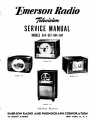
'Emerson Radio
SERVICE MANUAL
MODELS 614-637-644-647
.
MODEL 644
MODEL 614
MODEL 637
MODEL 647
Television Receivers
-•
EMERSON RADIO AND PHONOGRAPH CORPORATION
111 EIGHTH AVENUE
NEW YORK 11r N. Y,
Emerson Radio
TABLE OF CONTENTS
LIST OF TABLES
Table
Page
Par.
SECTION 1—GENERAL DESCRIPTION
1
2
Facilities
Specifications
3
4
DESCRIPTION
I
Tube Complements
II
Receiver Characteristics
III
Adjustments Control Settings
IV
Generator Frequencies
V
Audio I-F Alignment
VI
Video I-F Alignment
VII
Tuner Alignment
VIII Deflection Waveform Test Points
Page
_.._
.-.
3
4
11
14
15
16
17
18
SECTION 2—INSTALLATION
\
4
3
4
5
SECTION 3—OPERATION
5
5
1
2
SECTION 4 — CIRCUIT DESCRIPTION
1
?
3
4
5
6
7
7
General
...
Tuner
Video Section
. _
_
..
Deflection Section ,. —
Power Supplies
Intercarrier Sound
—
Deflection Yoke and Focus Coil Assembly
8
8
, __ 9
9
10
10
LIST OF ILLUSTRATIONS
Fig.
1-1
?
3
4
•>
6
7
8
ft
in
11
T>
13
Chassis Removal
Kinescope Replacement
Mechanical Deflection Adjustments
Electrical Deflection Adjustments ...
Alignment Test Equipment
Alignment
... .,
Voltage and Resistance Analysis ;
Deflection Circuit Waveforms
Production Changes
Secondary Area Reception
Cabinet Parts List
Chassis Parts List
.„
...
..«___,
. .
Page
Front View of Chassis 120098B
3
1-2
Tube Location Diagram
4
1-3
Video, Audio, and Oscillator Frequencies
4
3-1
Front Panel Controls _.
5
3-2
Test Pattern, Correctly Adjusted
6
3-3
Test Pattern, Tuning Misadjusted
6
3-4
Test Pattern, Excessive Contrast
6
3-5
Test Pattern, Excessive Brightness
6
3-6
Test Pattern, Vertical Hold Misadjusted
6
3-7
Test Pattern, Horizontal Hold Misadjusted
6
3-8
Test Pattern, Focus Misadjusted
6
3-9
Test Pattern, Weak Signal
6
4-1
Block Diagram—Chassis 12O110B, 120113B
7
4-2
Schematic Diagram of Tuner
8
5-1
Deflection Yoke and Focus Coil Adjustments
Combined Mechanical and Electrical Centering
SECTION 5—MAINTENANCE AND ALIGNMENT
1
DESCRIPTION
11
5-2
Focus Coil Adjustments, Mechanical Centering
5-3
Schematic Diagram Chassis 120110B
5-4
Rear Deflection Adjustments
14
5-5
Generator Matching Network
14
5-6
Scope Detector Network
5-7
Location of Alignment Points
15
5-8
Tuner Alignment Points
16
5-9
Side View of Tuner
17
5-10
Voltage and Resistance Diagram
18
5-11
Sweep Circuit Waveforms
19
21
5-12
High Voltage Power Supply, Chassis 120113B
20
22
5-13
Bottom View of Chassis
21
10
10
10
10
11
14
14
17
17
19
21
11
12,13
— 14
Emerson Radio
Section 1.
GENERAL DESCRIPTION
SYMBOL
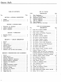
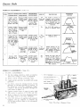
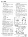
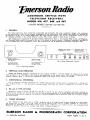
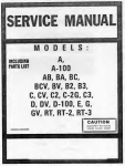
1. FACILITIES—Emerson Models 614, 637, 644,
and 647 are wide-band video receivers, providing dir eci-view high-definition pictures on ten or twelve-inch
electro-magnetic deflection kinescopes. All models incorporate several design features including intercarrier
sound, AFC in the horizontal sync circuits, automatic
gain control, a series-type transformer power supply,
and internal antennas.
Models 614 and 637 employ Chassis 120110B;
Models 644 and 647 use Chassis 120113B. Both chassis
are basically alike; the latter is modified to accommodate the larger kinescope, type 12LP4 or 12QP4.
Model 614 is housed in a plastic cabinet, and Model
637 is contained in a wooden cabinet; both are table
model receivers using a type 10BP4 picture tube.
Model 644 is housed in a table model cabinet; Model
647 uses a consolette-type of cabinet.
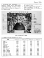
2. SPECIFICATIONS—
a. TUBE COMPLEMENTS: (Table 1).
NOT!1": The tube complements of both chassis
are alike, except for the kinescope. Chassis 120113B
uses type 12LP4 kinescope; some chassis may be
equipped with a type 12QP4.
LOW VOLTAGE
POWER SUPPLY
WOBBLE PLATE
LEVER
Vl
TT
1 . TRP
IM-
TYPE
V2
V3
V4
V5
V6
6AG5
6AG5
6AU6
6AL5
6AU6
12AU7
V7
V8
V9
V10
Vll
6AU6
6AU6
6T8
6V6GT
6SN7GT
V12
V13
V14
V15
6AL5
6SN7GT
6SN7GT
12AU7
V16
V17
V18
V19
V25
V27
V28
V29
6K6GT
6BG6G
1B3GT
6W4GT
) 10BP4* or
112LP4#
6J6
6AG5
5U4G
* Chassis 120110B
PICTURE CENTERING
LEVER (FOCUS COII
DEFLECTION YOKE
FUNCTION
First video i-f amplifier
Second video i-f amplifier
Third video i-f amplifier
Video detector and AGC
First video amplifier
Second video amplifier; second
sync amplifier
Sound i-f amplifier
Sound limiter
Sound disc, and audio amp.
Audio output
Hor. phase invert.; horizontal
control (d.c. amp.)
Hor. phase det. (sync disc.)
Hor. oscillator and discharge
Vert, oscillator and discharge
Sync sep. and d.c. restorer;
first sync, amplifier
Vertical output
Horizontal output
High-voltage rectifier
Horizontal damper
Kinescope
Oscillator and converter
R-f amplifier
Low- voltage rectifier
# Chassis 120113B
HIGH VOLTAGE
POWER SUPPLY
C-2l,C-39,C-4l,C-74
ON-OFF VOLUME
AND CONTRAST
AUDIO ISECTION
C-36.C-49
C-75
VIDEO I-F
SECTION
VERTICAL HOLD
TURRET
TUNER
BRIGHTNESS
AND HORIZONTAL HOLD
SELECTOR AND
FINE TUNING
Figude 1-1—Front View of Chassis 120110B
Emerson Radio
LOCATIONS
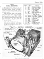
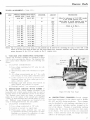
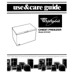
b. RECEIVER CHARACTERISES: (Table I I ) .
ITEM
DESCRIPTION
Voltage Rating
105-125 volts, 60 cycles a.c.
Power Consumption
All models— 190 watts
Current Drain
(At 117 volts a.c.)
Frequency Range
All' models — 1.7 amps.
.Intermediate
Frequencies
Video — 25.75 MC.
Audio — 4.5 MC.
54-88 MC.; 174-216 MC.
Input Impedance
300 ohms, balanced
Channel Selection
Twelve position, rotary turret
Chassis Models
Models 614, 637 — Chassis
1201 10B
Models 644, 647 — Chassis
120113B
Audio Output
2.5 watts
Figure 1-2 Tube Location Diagram
9S53ZO
OSCILLATOR FREQUENCY
CHANNEL LIMITS
CHANNEL
CH.2
81
54
3 . 1 ^ i , I I
7C
Jr.
59.75
AUDIO CARRIER
VIDEO CARRIER
55.25
61 25
76
174
CHANNEL
I
7
8
179.75
175.25
1
9
77.25
185.75
18125
187.25
1
193.25
109
1
i
LOW B A N D
8325
CH.7
CH.8
201
207
II
'°
J.
CH.6
103
87.7 5
81.75
2O4
1
CHS
6
I
180
AUDIO CARRIER
VIDEO CARRIER
!
s
71. '5
67.25
CH.4
93
I
OSCILLATOR FREQUENCY
CY
CHANNEL LIMITS
CH.3
67
CH.9
213
|
210
1
216
12
I
»
I
CH.IO
CH.M
CH.I2
CKI3
219
225
231
237
1
1
1
J
1
197.75
20!.75
203.75
215 75
HIGH B A N D
199.25
205.25
211.25
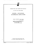
Figure 1-3—Video, Audio, and Oscillator Frequencies
Section 2.
INSTALLATION
1. PREPARATION FOR INSTALLATION —
All models are shipped complete, with the kinescope
in place and all adjustments properly set. Present
models are equipped with internal antennas and mechanical deflection centering. Initial production models do not include the built-in antenna and make use
of combined electrical and mechanical centering.
2. ANTENNA INSTALLATION—Chassis 12011013
and 120113B are designed to operate with high sensitivity and will provide excellent reception in many
areas with the internal antenna. If performance in a
particular locality is unsatisfactory disconnect the
internal antenna and install a portable or an outdoor
antenna, depending on reception conditions.
a. PORTABLE ANTENNA: Since surrounding
buildings and other objects can block out televi4
sion signals, an indoor antenna should be tried
in different locations before deciding on a permanent position. Uncoil the. transmission line from
the antenna base and connect to the terminals at
the rear of the chassis. Tune the antenna, after
turning on the receiver and adjusting the controls, by rotating and varying the length of the
telescopic arms for best reception. Both arms
should be adjusted to the same angular position
and extended to the same length.
PERMANENT ANTENNA: For outdoor , antenna installations, use a dipole or an array with
a combination of elements. An Emerson Tele-Ray
antenna is recommended, for best results. A 300ohm transmission line is required for connection
to the receiver.
Emerson Radio
3. RECEIVER INSTALLATION — Locate the receiver where a minimum of bright light falls directly
on the screen, although complete darkness is not recommended. Provide adequate ventilation by keeping the
back of the receiver away from the wall. Do not obstruct the ventilating slots at the rear of the cabinet.
All models are provided with a protective enclosure for the end of. the kinescope. The enclosure is
fastened to the rear of the chassis. Care should be exercised during installation so as not to strike or jar
the enclosure.
After completion of antenna and power connections, operate the receiver as outlined in Section III.
If a receiver fails to operate, or if operation is unsatisfactory, proceed with the following checks and adjustments.
CAUTJON
Only experienced personnel should attempt to make
these adjustments, as high voltage of ten kilovolts
is present at the kinescope.
a. MECHANICAL ADJUSTMENTS: For all
models, remove the chassis back and check all
tubes to make certain they are firmly seated in
their sockets. Remove the kinescope enclosure
and check the seating of the base plug. Inspect
the high-voltage anode connector.
The deflection yoke and focus coil have been properly positioned at the factory. The kinescope should
be seated back against the edges of the deflection
yoke assembly. Inspect the assembly to make
certain that all adjustment wingnuts are tight.
The ion trap should be positioned approximately
over the two internal flags near the base of the
kinescope.
b. ELECTRICAL ADJUSTMENTS: An adapter
line cord is required to operate the receiver for
the following preliminary adjustments.
1) Turn the OFF-VOLUME control a quarterturn clockwise to turn on the receiver. Set the
BRIGHTNESS control a half-turn clockwise
and turn the CONTRAST control counteiclockwise. Allow the tubes to warm up.
2) Set the SELECTOR control to an active channel and adjust the TUNING control for best
picture quality. A test pattern is preferable
for these adjustments.
3) Adjust the ion trap magnet by moving slowly
forward or backward while rotating slightly
around the neck of -the kinescope to obtain
maximum picture brightness. Reduce the
BRIGHTNESS control setting until the pattern is at7 approximately normal brilliancy. Adjust the 'FOCUS control, at the rear oi the
chassis, for maximum sharpness of raster lines.
Then readjust the ion trap for maximum brilliancy.
4) Adjustment of the deflection yoke assembly is
required if the raster is not horizontal. Loosen
the. center wingnut and rotate the assembly
slightly to correct this condition.
5) Centering of the raster in the mask is controlled by both electrical and mechanical adjustments, or by mechanical adjustments alone.
If this adjustment is required, refer to Section
V for operation of the chassis controls and positioning of the focus coil.
6) All electrical adjustments at the rear of the
chassis have been set at the factory. If the settings have been disturbed or if the kinescope
requires replacement, they must be carefully
readjusted in accordance with the procedure
outlined in Section V.
Section 3.
OPERATION
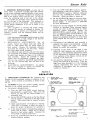
1. OPERATING CONTROLS—The operation and
function of the front-panel controls is identical for all
models. Seven controls are provided, as shown in figure 3-1.
2. TUNING—Tuning the receiver initially requires
operation of the various controls as indicated.
a. STATION SELECTION:
1) Turn the OFF-VOLUME control clockwise
approximately a quarter-turn. This turns the
receiver on and sets the sound volume to a
reasonable level.
2) Set the'SELECTOR control so that the desired
channel number is indicated on the edge of the
control. This control may be rotated in either
direction.
3) Allow approximately IS seconds for warmup.
(This time is necessary to allow the tubes to
attain the proper temperature for operation.)
4) If the desired station is-broadcasting, music or
speech will be heard. Adjust the TUNING
control for best picture quality. Readjust the
VOLUME or desired sound level.
5) Rotate the CONTRAST control to its extreme
counter-clockwise position.
CONTRAST CONTROL:
ADJUSTS PICTURE CONTRAST,
LIGHT OR DARK.
BRIGHTNESS CONTROL:—
ADJUSTS PICTURE
AVERAGE BRIGHTNESS.
•OFF-VOLUME CONTROL:
TURNS RECEIVER ON AND
ADJUSTS SOUND VOLUME.
HORIZONTAL HOLD CONTROL
STOPS HORIZONTAL MOTION
OF PICTURE.
VERTICAL HOLD CONTROL.
STOPS VERTICAL MOTION
OF PICTURE
INDICATOR CONTROL;
SELECTS STATIONS.
FINE TUNING CONTROL
ADUSTS RECEIVER
FOR BEST PICTURE
Figure 3-1—front Panel Controls
Emerson Radio
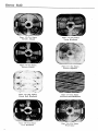
Figure 3-2—Test Pattern
Correctly Adjusted
Figure 3-4—Test Pattern
Excessive Contrast
Figure 3-3—Test Pattern
Tuning Misadjusted
Figure 3-5—Test Pattern
Excessive Brightness
I ,r' .,'
V"
'-f
m_ .«. •
Figure 3-6—Test Pattern
Vertical Hold Misadjusted
Figure 3-7—Test Pattern
Horizontal Hold Misadjusted
Figure 3-8—Test Pattern
Focus Misadjusted
Figure 3-9—Test Pattern
Weak Signal
Emerson Radio
6) Rotate the BRIGHTNESS control to the maximum counter-clockwise position and then adjust slowly clockwise until light is just visible
on the screen. Rotate in reverse direction until light just vanishes.
7) Adjust the CONTRAST control until a picture appears on the screen and desired contrast is attained. A further reduction in the
BRIGHTNESS control setting may improve
the apparent contrast of the picture.
8) If the picture moves vertically or horizontally,
make the adjustment indicated in steps 9 and/
or 10.
9).Adjust the VERTICAL HOLD control until
the picture stops moving up or down. Proper
operating setting of this control is in the center of the range over which the picture remains
stationary.
10) Adjust the HORIZONTAL HOLD control
until picture stops moving from side to side.
1 1 ) Readjust the CONTRAST control until the
desired picture intensity is obtained. It may
be necessary o readjust the BRIGHTNESS
control slightly at the same time for optimum
brilliance.
12) After the receiver has been operating for some
time, it may be necessary to readjust the TUNING control slightly for best picture quality.
1). CHANGING STATION DURING OPERATION :
1) Set the SELECTOR control to the proper
channel number.
2) Readjust the TUNING control if necessary to
obtain best picture quality.
3) Readjust the CONTRAST control slowly until the desired picture quality is obtained.
4) Readjust VOLUME to suitable level.
5) Readjust BRIGHTNESS control for desired
brilliancy.
c.
CHECKING OPERATION: The use of automatic frequency control in the sync circuits of
the receiver makes readjustments of the VERTICAL HOLD and HORIZONTAL HOLD
controls infrequent provided the control settings for proper operation are not disturbed.
Figures 3-2 through 3-9 indicate correct and
incorrect adjustment of the various controls.
Proper operation may be obtained by operation
of the associated control.
Section 4.
CIRCUIT DESCRIPTION
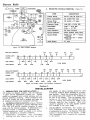
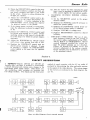
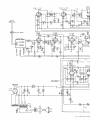
1. GENERAI^-Chassis 120110B and 120113B are
basically alike; the latter is modified to accommodate
a 12-inch kinescope and contains some changes in the
high-voltage power supply circuits. Both chassis contain twenty-three tubes including the kinescope and
low-voltage rectifiers. The chassis use the intercarrier
T
1
v ;B
R-F t
6AC 5
V - 2 7A
V - 2 78
CONVE
ATOR
6. 6
V- 7
1
AUDIO I-F
AMP
64U6
1
1
6J B
method of sound reception, with the 4.5 me. audio i-f
produced by heterodyning the video and audio carriers
at the output of the video detector. The various stages
of the receivers are indicated in the block diagram, figure 4-1.
V-8
AUDIO I-F
LIMITER
6AU6
1
_J
V-9
V-IO
DISC. AND
AUDIO
AUOIO AMP
OUTPUT
•Ti
SV60T
-<
1
I2575MC
'I2I.25MC.
V-25
10 B °4 OR IZLP*V-l
1 ST VIO I-F
V- 4
AMP
V-2
2ND VIO I-F
AMP
V-3
3RD VID. I-F
AMP
AND AGC
6AG5
SAGS
SAUS
SALS
VID.
DET.
V-5
1 ST VIDEO
AMP
6AU6
V-6A
2 NO VIDEO
V-I5A
SYNC. SEP.
0 C
AMP.
I2AU7
RES.
12 AU7
_J
V-I5B
1ST SYNC
AMP
I2AU7
V-6B
2ND SYNC.
AMP.
I2AU7
r
V-l A
HOR PH.
V-IZ
HOR.PH.
INV.
SSMTOT
V-MB
HOR CONT
V-13
HOR.
OSC.
V-19
V-17
HOR
AMP.
6AL5
6SN7GT
6S N7
68G60
I
I05-I25V
6 0 ~ A C.
V-2 9
L.V. RECT.
5U4G
E
B1L_
V-14
VERT
VERT. AMP
V -IB
H.V. RECT.
6K6GT
IB3GT
V-IS
OSC.
•—
6SN7GT
B-
HOR. DAMP
DET.
Figure 4-1—Block Diagram, Chassis 120110B, 120113B
6W4GT
-tf
Kf
Emerson Radio
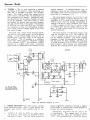
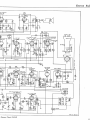
2.
TUNER — The r-f. unit constitutes a separate
sub-chassis of the receiver. This sub-chassis contains the r-f amplifier, converter, and oscillator
stages. The channel switch, fine tuning control,
tuned circuits, and first video i-f transformer are
also contained on this chassis. Tuning and tracking adjustments for all twelve channels currently
in use are provided. The tuner serves to select
and amplify the desired video and audio frequencies and convert them to the carrier i-f frequencies
of 25.75 me. for video and 21.25 me. for audio.
No separation of these two intermediate frequencies is mads, and the complete signal is fed to the
first video i-f stage.
various channels. A variable-dielectric type of
condenser is used for fine tuning of the oscillator.
The output of the converter is conected to doubletuned first i-f transformer ( T l ) .
The tuner uses a rotary turret carrying individual coils for each tuned circuit, for each channel
setting. A type 6AG5 (V28) serves as the r-f
amplifier and a type 6J6 (V27) as the converter
and oscillator. The r-f amplifier is a wideband,
tuned stage whose output is inductively coupled
to the converter (V27). The oscillator (V27B)
operates in a Colpitts type circuit. Individual
slugs provide for alignment of the oscillator on the
The input capacity of V27A and trimmer A16
tune the converter coil (L4). The oscillator coil
(L5) is wound on the same form with L3 and
L4, for inductive coupling. The initial oscillator
frequency is fixed by permeability tuning of L5
and the preset .5-3 mmf. trimmer. The frequency
is varied by means of the TUNING control (3-5
mmf. trimmer) which consists of a spiral-shaped
dielectric disc rotating between fixed stator plates.
The center-tapped primary (LI) of the r-f coil
is designed to match a balanced 300-ohm line. The
secondary (L2) is tuned by the input capacity of
V28 in series with the parallel combination of
trimmer A14 and a 5 mmf. condenser. The output
of V28 is coupled to V27A by L3, which is tuned
by trimmer A15 and 'the output capacity of the
tube. A 10K resistor loads L3 to provide the
required band pass.
950098
270
ALL RES. IN OHMS,
CAP. IN MMF, UNLESS
OTHERWISE SPECIFIED
6.3 AC
Figure 4-2 Schematic Diagram of Tuner
1. VIDEO SECTION—The video section consists
of the following sections: video i-f; video detector and
automatic gain control; video amplifier and d.c. restorer.
a.
VIDEO I-F: Both the 25.75 me. video carrier
and 21.25 me. audio carrier are amplified by three
wide-band i-f stages. The four tuned cicruits are
peaked at .different frequencies, forming a staggertuned system of relatively flat overall response to
produce the required bandpass.
Self-resonant, slug-tuned coils are used in the
i-f transformers. Two stagger-tuned i-f transformers (T2, T3) follow the overcouplscl first i-f
( T l ) . T2 is provided with a 21.25 me. trap to
Emerson Radio
attenuate the audio i - f . An overcoupled i-f (T4)
completes the amplifier stages and feeds the video
detector (V4).
The audio level is maintained just below the
point of intertcrence with the video i-t. However,
the audio i-t is not completely rejected, as the audio
signal is recovered (ac the output ot the video detector) by heterodyning with the video i-f. The
4.5 me. beat between me video and audio intermediate frequencies is obtained from the shunttuned circuit consisting of L2 and C79 and is fed
to the first audio i-f amplifier (V7).
b. VIDEO DETECTOR AND A.G.C. :The video
detector (V4A) rectifies the negative portion of
the video i-f. The resultant signal is coupled
through peaking coil LI to the grid of the first
video amplifier ( V 5 ) . V5B acts as the automatic
gain control and develops a delayed negative A.G.C.
voltage which is used to bias the first two video
i-f stages and the r-f amplifier.
c. VIDEO AMPLIFIER: The video amplifier consists of two stages (V5 and V6A). The second
stage is series-peaked and is coupled to the grid
of the kinescope (V25) and the sync separator
and d. c. restorer (VISA). The output signal of
V5 is varied by the CONTRAST control (R19)
which varies the bias of VS, to control the signal
input to V6A.
d. D. C. RESTORER AND SYNC CLIPPER:
The output of the video detector contains both a.c.
and d.c. components of the video signal, as well
as the blanking and sync pulses. Since the video
amplifiers will not pass the d.c. component of the
video signal, the background level of the picture
will vary. The d.c. restorer (VISA) develops a
bias voltage across R24 which varies with the
average video signal level. This bias voltage is
fed to the grid of the kinescope, thus maintaining
the proper brightness level. The video sync pulse
output of VISA, developed across R28, is coupled
through C22 to the first sync amplifier (V15B).
4. DEFLECTION SECTION—The sync and sweep
stages produce and control the deflection of the electron beam in the kinescope. The horizontal sweep circuits incorporate a horizontal phase detector (sync
discriminator) to maintain automatic sync with the
horizontal pulses of the video signal.
a. SYNC AMPLIFIER AND INVERTER: The
sync pulse output of VISA is amplified by two
triode stages (VISE and V6B) and fed to the
horizontal phase inverter (V11A). The integrating network of the vertical deflection circuit is
coupled to the output of VI1 A, which provides
push-pull' output for I'le horizontal sync discriminator ( V I 2 ) .
b. HORIZONTAL SWEEP: The horizontal deflection circuits contain an automatic frequency
stabilizing arrangement which improves stability
and ease of operation. The phase inverter (V11A)
feeds the horizontal sync pulses to the horizontal
phase detector (V12). At the same time, V12
receives voltages fed back from the horizontal out
put (V17) through CSS. Any phase shift between
the horizontal sync pulses and the horizontal oscillator signal will cause the input voltage applied
to one diode section of V12 to differ from that of
the other and result in a d.c. bias voltage on the
grid of the horizontal control tune ( V l l - b ) . This
bias voltage will be proportional to the phase displacement between the incoming sync pulses and
the horizontal oscillator voltage and of a polarity
determined by the lead or lag of the oscillator frequency. The plate resistance of VHP) is part of
the bias network of the grid circuit of the horizontal oscillator ( V l o ) . The output of the phase detector (V12) will ihus synchronize the oscillator
to the horizontal pulses of the video signal.
The horizontal blocking oscillator (V13) operates
at a frequency determined by C57, R75, R76, and
the plate resistance of V I I B . The horizontal sync
pulses cause V13 to lock in at the sync frequency
when the HORIZONTAL HOLD control \R75)
is properly adjusted. The sweep voltage output
of V13 is developed across R79 and is ted to the
horizontal output tube ( V I 7 ) . The signal level
to the horizontal output tube is adjusted by the
HORIZONTAL DRIVE control, R80.
V19 supplies the required driving power for the
horizontal deflection coils (L9). 'ihe output of
V17 is coupled to the horizontal deflection coils
through output transformer T9. A portion of the
output transformer secondary is shunted by the
HORIZONTAL SIZE control L6. By varying
the inductance of L6, the horizontal sweep current
may be controlled.
The horizontal damper tube (V19) acts to damp
out oscillations which occur over part of the horizontal scanning cycle. The HORIZONTAL LINEARITY control (L7) helps provide a linear
trace. V19 is a type 6W4 to eliminate the need
for a separate damper filament winding,
c. VERTICAL SWEEP: Vertical oscillator V14 is
free-running and operates at a frequency determined by C71, R95, and the VERTICAL HOLD
control (R94), in the absence of a vertical sync
pulse. The integrated sixty-cycle sync pulse derived from the video signal reaches the grid of
V14 just before it would normally trip. This sync
pulse is great enough to drive the tube to conduction and cause it to lock-in at the sync frequency.
The sync pulse thus maintains control of the vertical oscillator sweep frequency when R94 is correctly adjusted.
The output of V14 is fed to the vertical output
stage (V16) through C72. The output of V14 is
controlled by the VERTICAL SIZE control
(R96). R100 varies the operating point of V16
by varying the bias, acting as the VERTICAL
LINEARITY control The sweep voltage of V16
is coupled to the vertical deflection coils (L8) by
means of the vertical output transformer ( T i l ) .
5. POWER SUPPLIES — Two power supplies are
used to supply the required voltages. The low voltage
supply uses a transformer and full-wave rectifier. The
high voltage supply for the kinescope is of the fly-back
lype and is energized by the horizontal output tube.
a. HIGH VOLTAGE SUPPLY: The high voltage
power supply makes use of the energy supplied to
the horizontal output transformer by VI7. When
the plate current of VI7 is cut off at the instant
Emerson Radio
of retrace of horizontal scanning, the field built
up in the primary collapses and induces a highvoltage. This voltage is applied to the high-voltage
rectifier (V18). From 8.5 to 10 kilovolts is produced by the power supply. The rectified voltage
is filtered by C63 and R89, and applied to the
second anode of the kinescope. Chassis 120113B
differs from Chassis 1201 IB in that C63 is returned to B—, instead of the plate of VI9.
b. LOW VOLTAGE SUPPLY: The low-voltage
supply uses a full-wave rectifier (V29) and transformer (T12). A series arrangement is used to
supply plate voltage, to reduce current requirements. As a result, separate filament windings
are used to keep the heater-cathode potentials
within ratings, and the electrolytic filter condensers are not grounded to the chassis. The centertap of T12 is not grounded but is negative (B—)
with respect to ground. The cathodes of the sweep
circuit and video amplifier tubes are negative to
ground (about -205 volts) and the heaters are
conected to the ungrounded filament winding (Y).
6. INTERCARRIER SOUND—The audio circuits
are conventional. The 4.5 me. heterodyne between the
video and audio, i-f carriers is taken from the shunttuned circuit (L2, C79) at the output of the video detector (V4). The 4.5 me. signal is amplified by the
audio i-f amplifier (V7), whose output is coupled to
the limiter (V8). V8 feeds the discriminator (V9A) ;
the output of the discriminator is amplified by V93,
and the audio output (V10).
7y DEFLECTION YOKE AND FOCUS COIL
ASSEMBLY: The deflection yoke and focus coil
form a complete assembly. The yoke contains the
vertical and horizontal deflection coils (L8 and
L9). The focus coil (L10) combines a permanent
magnet with the electromagnet (PM and EM).
The yoke and focus coil are independently adjustable.
Vertical centering is accomplished by mechanical adjustment of the focus coil; horizontal centering is done electrically by the HOR. CENTERING control (R103). Later production of Chassis 120110B and 120113B makes use of a pivoted
mounting for the EM-PM focus coil, together
with a "wobble plate" to provide for mechanical
adjustment of horizontal and vertical centering.
The "wobble plate" consists of a ring of permeable material (steel) surrounding the neck of the
kinescope, adjacent to the EM-PM focus coil.
The plate may be moved in a plane at right-angles
to the axis of the kinescope, both vertically and
horizontally, by means of a slotted section and
lever. In addition, the focus coil may be tilted in
both directions by means of a second lever which
is adjustable from the rear of the cabinet, without
removing the back. This enables precise mechanical control of centering.
Section 5.
MAINTENANCE AND ALIGNMENT
1. GENERAL—All adjustments must be made only
by qualified service technicians. Unsatisfactory operation should be analyzed and circuits checked systematically to locate and correct sources of trouble.
WARNING
High voltages in excess of 8000 volts are present
in the chassis, during operation. Exercise care in
servicing the receiver, when energized. Do not
remove, handle, or replace the kinescope unless
gloves and goggles are worn.
2. CHASSIS REMOVAL—To remove the chassis,
follow the outlined procedure.
a. Pry off all control knobs.
b. Remove the six screws which fasten the back in
place.
c. Remove the speaker plug.
d. Remove the four chassis bolts and carefully slide
the chassis from the cabinet. When inverting the
chassis, place a supporting block under the power
transformer.
3. KINESCOPE REPLACEMENT —
CAUTION
Before removing the kinescope, discharge the tube
by cdnnecting an insulated test prod to the chassis
and to the high-voltage anode. Wear gloves and
goggles before handling the tube.
To remove the tube, proceed as follows:
a. Disconnect the high-voltage lead at the top of the
kinescope and discharge the tube.
b. Remove the enclosure which protects the base of
the kinescope.
10
c.
d.
Remove the tube socket and slide off the ion trap.
Loosen the hold-down strap at the front of the
tube and carefully withdraw the kinescope forward from the deflection yoke and focus coil assembly.
To install a new kinescope, follow the above procedure in reverse. Make certain that the tube is
seated against the edges of the deflection yoke
assembly, with the high-voltage anode connection
at the top. In replacing the ion trap, position the
unit so that the arrow points towards the front of
the chassis.
NOTE
Whenever the kinescope is removed or replaced,
the mask should be carefully cleaned with a soft,
lintless cloth. Do not use carbon tetrachloride or
any cleanser containing abrasive material. The
face of the kinescope should also be wiped clean,
before replacing the chassis in the cabinet.
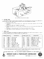
4. MECHANICAL DEFLECTION A D J U S T MENTS — See figure 5-1. Replacement of the kinescope or of any of the components of the deflection
system will require readjustment of the deflection yoke
assembly, focus coil, and ion trap.
NOTE
Before making any deflection adjustments, make
certain that the enclosure is in place, covering
the base of the kinescope, and is firmly fastened.
The adjustments to the focus coil can be made
through openings provided in the enclosure.
Emerson Radio
-,
C3
Figure 5-1—Deflection Yoke and focus Coil Adjustments,
Combined Mechanical and Electrical Centering
a.
DEFLECTION YOKE: If the raster lines are
not horizontal, loosen the center wingnut (Al)
and rotate the yoke coil assembly to correct the
condition. Tighten the wingnut firmly.
The position of the assembly along the axis of the
kinescope is fixed by the two outer wingnuts (Bl,
B2). The yoke should be positioned approximately at the center of the slots.
ANODE CONNECTION
too close to the. deflection yoke as the range of
adjustment of the FOCUS control (R55) will
be limited.
To center the raster for models provided with
a "wobble plate" and focus levers, proceed as follows (See figure 5-2):
- 1 ) Adjust the focus lever to make the focus coil
concentric with the neck of the kinescope.
Loosen the three mounting nuts (Bl, B2, B3)
slightly, if required.
2) Loosen the single wobble-plate mounting screw
(A) and slide the plate vertically or horizontally, by means of the lever, to approximately center the raster. Tighten the mounting screw.
3) Readjust focus coil lever, if required, to exactly center the raster in the mask. Both horizontal and vertical adjustments are ma'de simultaneously. Tighten the mounting nuts (Bl,
B2, B3) after positioning.
4) Note that normally only the vernier adjustment (focus coil lever) is required, unless the
kinescope has been replaced. The wobbleplate lever has been initially positioned at the
factory and usually will not require readjustment.
c.
ION TRAP : Adjust the position of the ion trap
as outlined in Section II.
5. ELECTRICAL DEFLECTION ADJUSTMENTS
— The electrical adjustment controls are located at
the rear of the chassis. For access to the adjustment
controls, remove the cabinet back. Use an adapter
line-cord to complete the a-c. power connections, with
the back removed.
Before proceeding with adjustment of the rear
controls, tune in a test pattern and set the front panel
controls for the best picture, as outlined in Section III.
Complete the adjustments of the deflection yoke and
focus coil before setting the electrical controls. Adjust
the controls in the order indicated.
a.
ADJUSTMENT
(Table III).
STEP
DEFLECTION
YOKE
ADJUSTMENT
CONTROL
CONTROL SYMBOL
b.
Centering
EM-PM FOCUS COIL: For models not provided with a "wobble plate," adjust the upper screw
(Cl) of the focus coil to center the raster vertically. Slight variation of the two side screws
(C2, C3) may be required to complete the adjustment. The focus coil should not be positioned
ADJUSTMENT
1
Vertical
Size
R-96
Affects bottom section of
raster and overall size. Adjust to fill the mask vertically (height).
2
Vertical
Linearity
R-100
Affects top section of raster and overall size. Adjust
for best linearity.
3
Horizontal
Drive
R-80
Controls signal to horizontal output V-19. Adjust for
best linearity.
4
Horizontal
Linearity
L-7
Affects linearity of left and
center sections of raster. Adjust in conjunction with
R-80, for best linearity.
5
Horizontal
Size
L-6
Adjust to fill the mask
horizontally (width).
6
Horizontal*
Centering
R-103
Adjust to center raster horizontally.
7
Focus
R-55
Controls current through focus coil L-10. Adjust for
sharpest line detail.
FOCUS CONTROLLEVER
Figure 5-2—Focus Coil Adjustments, Mechanical
SETTINGS:
Emerson Radio
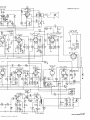
Figure 5-3—Schematic Diagr
Emerson Radio
PART No. 950127
Diagram, Chassis 120110B
13
Emerson Radio
Proper adjustment of the HORIZONTAL and
VERTICAL LINEARITY controls, and the SIZE
controls should result in test patterns in which the
circles are round and the wedges are linear and equal.
The test pattern circles should be concentric with the
curved sides of the mask.
955282
120
TO
TO
50
GEN.
/
OR HORZONTALLY IN FRONT
OPENING , ADJUST THE LEVER
EXTEND NG FROM BACK COVER.
H V
PICTURE
CAN
LEVER
--''
i*T"~""|^H>.
S?
|H^'-'JT"''*1
11 !
1
I
</fS\^
Wtr- '
f*\)
'!
f
\.fU\
®
o)
VACUUM-TUBE VOLTMETER:
1) A diode probe for high-frequency measurements is desirable.
2) High input impedance with provision for lowvoltage measurement (three or five volt scale).
@ SPEAKER
L-7
R-80
HOR.
Figure 5-5—Generator Matching Network
II
INTERLOCK
(o
J
®
HOR.
SIZE
LIN.
o
HOR.
DRIVE
R-IOO
R-9«
VERT.
LIN.
VtRT.
SIZE
o
o
R-38
R-103 *
o Ao
FOCUSZ_L_iMOR .*
/
CENT.
CODE NUMBER—/
Figure 5-4—Rear Deflection Adjustments,
*For chassis not equipped with wobble plate and
centering lever.
6. ALIGNMENT TEST EQUIPMENT — Proper
servicing and alignment of Chassis 120110B and 120113B requires the equipment indicated.
a. SWEEP GENERATOR:
1) Frequency ranges of 18 to 30 MC., 50 to 90
MC., and 170 to 225 MC.
2) Sweep width variable to 10 MC.
3) Output of at least 0.1 volt, with an attenuator
for adjustment of output.
4) Constant output over sweep width, with flat
output on all ranges and at all attenuator positions.
5) Output impedance of 300 ohms, for r-f alignment, or matching network. Seefigure5-5.
b. MARKER GENERATOR:
1) Frequency ranges of 4 to 30 MC. and 50 to
225 MC., for i-f and r-f alignment. The marker generator must provide an accurate (crystal
calibrated) frequency of 4.5 MC. for audio i-f
alignment, and accurate frequencies from 21.25
MC., to 25.75 MC., for video i-f alignment.
The required r-f requencies from 50 to 225
MC., as tabulated below, may be provided by
a calibrated signal generator or a heterodyne
frequency meter with crystal calibrator.
2) Output of at least 0.1 volt, with an attenuator
for adjustment of output.
GENERATOR FREQUENCIES: (Table IV).
CHANNEL
2
3
4
5
6
7
8
9
10
11
12
13
14
-
120
. — —: — :
USE CARBON RESSTORS ONLY.
NECK OF TUBE
®
\
— :i^:
J& . J<^
II
L-6
-AAA/
1
fixx t/
x'_>^
[§T|
RECEIVER
VIDEO
CARRIER
MC
55.25
61.25
67.25
77.25
83.25
175.25
181.25
187.25
193.25
199.25
205.25
213.25
AUDIO
CARRIER
MC.
59.75
65.75
71.75
81.75
87.75
179.75
185.75
191.75
197.75
203.75
209.75
215.75
OSCILLOSCOPE:
1) Vertical input should be provided with a calibrated attenuator and low-capacity probe.
2) Flat vertical amplifier frequency response, with
good low frequency response.
3) Adequate vertical sensitivity.
SCOPE DETECTOR: Required for alignment of
over-coupled first i-f Tl. Seefigure5-6.
20K
IN34
j
100MMF **
:i
IXU
>IMEG.
.005 MFD
|
/|
^Z00y\
L
r
TO TEST POINTS
IN RECEIVER
(KEEP LEADS SHORT)
Figure 5-6—Scope Detector Network
7.
a.
ALIGNMENT—
AUDIO I-F ALIGNMENT:
1) Disconnect the antenna and remove the chassis from the cabinet. Use an adaptor line cord
to operate the receiver.
2) Set the CONTRAST control at the center of
rotation and retain at this setting for all i-f
adjustments.
3) The waveforms shown in the response curves
may be inverted depending on the number of
amplifying stages in the vertical amplifier of
the scope being used.
4) When the marker signal is coupled in parallel
with the sweep generator, the signal should be
Unmodulated and attenuated so that only a
small pip is visible. Use an accurate, crystalcontrolled marker generator.
5) Connect the sync sweep voltage from the sweep
signal generator to the horizontal input of the
scope for horizonal deflection.
6) Refer to figure 5-7 for location of alignment
points; figure 5-3 for the schematic diagram.
7) Set the receiver to Channel 3.
Emerson Radio
figure 5-7—Location of Alignment Points
AUDIO I-F ALIGNMENT: (Table V).
SIGNAL GENERATOR INPUT
CONNECTION FREQUENCY
MEASURING
INSTRUMENT
ADJUST
PROCEDURE
1
Marker generator
through .OO1
mfd. to pin 2 of
V4. Low aide
to B—.
Marker—4.5
MC.
Connect v.t.v.m.
Connect v.t.v.m.
to junction of
R38 and C27.
Low side to B—.
C79
Peak for maximum response. Adjust generator
input to produce one volt
reading on v.t.v.m.
2
n
Marker—4.5
MC.
»
3
Connect sweep
generator in
parallel with
marker gen.
STEP
4
b.
>>
Replace v.t.v.m.
Sweep—4.5
MC. (450 KC. with scope consweep) Marker nected through
10K resistor to
—4.5 MC.
junction of R44
and C31.
n
H
VIDEO I-F ALIGNMENT:
1) Retain the control settings used for audio i-f
alignment.
2) Connect a 3 volt bias battery from the junction
of Rl, R6, and Rll (negative terminal), to
chassis (positive terminal) for step 5.
T5
(Top and
bottom)
Peak for maximum
response
T6
(Bottom)
Position 4.S MC. marker
at center of S-curve, by
adjusting secondary
bottom.
T6
(Top)
Peak primary for maximum amplitude and
linearity. Repeat step 3.
RESPONSE
CURVES
*ISOKC.
«*MC.
^-/
,~^
/
-ISOKC.
3) Shape the overall response curve, after individual peaking of stagger-tuned and overcoupled i-f transformers. Maintain output of
the sweep and marker generators at a minimum, to prevent distortion of the response
curve.
15
Emerson Radio
VIDEO I-F ALIGNMENT: (Table V I ) .
STEP
1
2
3
SIGNAI GENER ATOR INPUT
CONNECTION FREQUENCY
Lightly couple
Sweep- 23.5 MC Connect vertical
marker gen. to
input of scope
(10 MC. sweep)
through 10K repin 1 of V3:
Marker-25.75
Sweep gen. from
sistor to junction
MC.
pin 1 to chassis,
of Ll, R16,
and C16. Low
:hrough .001 mfd.
side to chassis.
Connect marker Sweep -23. SMC.
and sweep gener- (10 MC. sweep)
Marker-25.25
ators to pin 1
MC.
of V2, through
.001 mfd. Low
side to chassis.
5
»
\
/ XI\
/
T2
(Top and
bottom)
TJ
25.75MC. M A R K E R
^t"^" *~\
Set 25.25 MC. marker as
shown on response curve.
T3
Sweep -23. SMC. Connect scope
(10 MC. sweep) through detector
network to pin 1
Markersof V3. Low side
22.8 and
to chassis.
21.25 MC.
4
RESPONSE
CURVES
PROCEDURE
T4
Set marker as shown on
(Top and
response curve; marker
bottom)
should be 10% down. Adjust sweep generator input to produce one volt
at junction of Ll, R16,
and C16.
Tl
(L7 and
L9)
MC.
16
»
ADJUST
Sweep generator Sweep- 23.5 MC. Connect scope
coupled to con- ( 10 MC. sweep) through detector
Marker-25.75 network to pin 1
verter (V27) inof V2. Low side
MC.
put, using three
to chassis.
turn loop slipped
over tube. Marker
gen. in parallel.
Low side to
chassis.
Sweep - 23.5 MC
Connect AGC
bias battery as
( 10 MC. sweep)
indicated above. !
Markers25.75 MC.
and 22.25
c.
MEASURING
INSTRUMENT
Connect scope
through 10K resistor to junction
of Ll, R16 and
C16. Low side to
ciiassis.
TUNER ALIGNMENT:
1) Set fine tuning control to center of rotation.
Retain tbis setting or entire r-f alignment.
2) Retain control settings previously used.
3) Couple marker generator in parallel with sweep
generator.
4) Use 10 inc. sweep lor sweep generator. Couple
generator to antenna terminals of receiver. If
the sweep has a 50 ohm, unbalanced output,
connect to the antenna terminals through network shown in figure 5-5.
5) Connect vertical input of scope in scries with
10K resistor to junction of Ll, R16, and C16.
6) Refer to figure 5-8 for tuner alignment points,
and figure 4-12 for the tuner schematic.
7) A14, A15, A16 are r-f amplifier and converter
trimmers and are adjusted on Channel 12;
A13-A2 are oscillator slugs for the corresponding channels.
Set marker as shown on
response curve.
J25.7SMC.
\I
MARKER
\
/JlZZ.BO MC.
/ l \R
y\
Adjust primary of T2
(top) to position 22.8
MC. marker; adjust T2
trap (bottom) to position
21.25 MC. marker.
Vm
/
T2,
T3
\
T^K
Adjust T2 (top) and T3
to give overall response
shown. T2 (tor>) adiusts
bandwidth; T3 positions
video carrier (25.75 MC.) M A R K E R / !
depending on accuracy of
/ BANDWIDTH
adjustment of Tl (25.75
MC. marker).
s~*—•"•>
/
FIRST I-F TRANSFORMER T-l
t-9 1
(SEC.) *7
\y
\
IMARKER
\
3.5 MC
R^ AMPLIFIER
SAGS .
R-F AMP. INPUT
TRIMMER A-14
figure
?-8—Tuner Alignment
Points
Emerson Radio
TUNER ALIGNMENT: (Table V I I ) .
STEP
1
SIGNAL GENERATOR INPUT
SWEEP GEN. MAR. GEN.
209.75 MC.
207.0 MC.
2
»
3
213.0
201.0
195.0
189.0
183.0
177.0
85.0
79.0
69.0
63.0
57.0
4
5
6
7
8
9
10
11
12
13
ft
MC.
MC.
MC
MC.
MC.
MC.
MC.
MC.
MC.
MC.
MC.
215.75
203.75
197.75
191.75
185.75
179.75
87.75
81.75
71.75
65.75
59.75
MC.
MC.
MC.
MC.
MC.
MC.
MC.
MC.
MC.
MC.
MC.
CHANNEL
ADJUST
PROCEDURE
12
A12
12
A14,
A15,
A16
Adjust for placement of 21.25 MC. marker
as per overall response curve.
Adjust shape of overall response curve for
maximum amplitude and bandwidth.
13
A13
Adjust as in Step I.
11
»
9
All
A10
A9
8
A8
»
7
»
6
A7
A6
5
A5
j>
>»
4
A4
»>
3
A3
2
A2
»
»
10
»>
»
NOTE: The r-f response curve of the tuner, on each channel may be observed by connecting the scope in series with a 10K
resistor to the test point shown in figure 5-9. The curves should have maximum amplitude and flatness, consistent with
proper placement of the 21.25 me. marker on the i-f response curve.
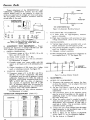
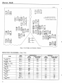
8. VOLTAGE AND RESISTANCE ANALYSIS—
Voltage and resistance readings are indicated in figure
5-10, to aid in servicing the chassis. The diagram indicates typical values obtained under the following conditions.
a.
ANALYSIS CONDITIONS:
1) Line voltage maintained at 117 volts for voltage readings.
2) Measurements made with voltohmyst or equivalent.
3) All voltage measurements are in + d.c. volts
and resistance in ohms, unless otherwise noted.
4) Socket connections are shown as boUom v'<"vs.
Measured values are from socket pin to B—,
unless otherwise stated.
5) Readings made with antenna disconnected, no
signal applied and controls at normal.
6) Readings marked * are measured to ground.
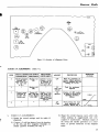
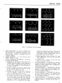
9. DEFLECTION CIRCUIT WAVE FORMS —
See figure 5-11. The sweep voltages produced in the
horizontal and vertical sweep circuits may be used in
locating defects in the deflection section of the chassis.
Two separate wave forms are shown at various test
points up to the output of the second sync amplifier
(V6B), as both horizontal and vertical pulses ar? present. Different sweep frequencies are required at the
scope to distinguish between the sync pulses.
a. ANALYSIS CONDITIONS:
1) Line voltage maintained at 117 volts.
2) Controls at normal ; no signal input.
3) Peak-to-peak values indicated may vary due
to component tolerances and response of scope.
Readings are obtained by calibration of scope,
prior to observation of waveforms.
OSC. AND CONV
TEST POINT
TRIMMER »-!«
R-F OUTPUT, CONV.,
AND OSC. COILS
(L-S,L-4,L-5>
Figure 5-9—Side View Tuner
10. PRODUCTION CHANGES—Several changes
have been incorporated in the chassis used in Models
614, 637, and 644, during production. These changes
may be identified by code markings consisting of a triangle containing a particular number, stamped at the
rear of the chassis. Presence of a particular marking
indicates that the revisions described have been made
in the chassis. The various revisions are summarized
below. Unless otherwise noted, the changes have been
added to all subsequent models.
17
Emerson Radio
ALL VOLTAGE AND RESISTANCE
MEASUREMENTS MADE TO B- ( R - 6 1 )
Figure 5-10—Voltage and Resistance Diagram
DEFLECTION WAVEFORMS: (Table VIII).
TUBfi
Sync Separator
V-15A
First Synci Amp.
V-15B
Second Sync. Amp.
V-6B
Hor. Phase Inv.
V-11A
Phase Det.
V-12
Hor. Control
V-11B
Hor. Osc.
V-13
Vert. Osc.
V-14
Vert. Output
V-16
18
TEST
POINT
Pin 3
Pin 1
Pin 6
HORIZONTAL
KEY
PEAK to PEAK
LETTER
VOLTAGE
AH
22.3
BH
8.9
CH
11.4
VERTICAL
KEY
PEAK to PEAK
LETTER
VOLTAGE
AV
36.6
BV
11.3
CV
18.5
Pin 6
DH
77.4
DV
117
Pin 2
EH
19.0
EV
40.2
Pin 5
Pin 7
Pin 5
GH
HH
IH
8.7
6.0
14.5
GV
HV
9.7
9.2
Pin 5
Pin 1
Pin 4
Pin 2
Pins 3, 4
JH
KH
55.4
53.5
LV
MV
NV
178
100
303
Emerson Radio
Figure 5-11—Deflection
a.
b.
c.
CODE MARKING — E: Part No. 925162, C21,
C36, and C49; C49 (80 mfd.) is marked A, and
C21 (10 mfd.) is marked Q due to incorrect condenser marking, instead of markings shown on
schematic diagram.
CODE MARKING — C: No Pyramid paper
tubular condensers used.
CODE MARKING-TRIANGLE 1: Revisions
to correct picture flicker.
1) Removed red lead from B+ 125-volt point on
terminal strip near fourth i-f and from pin 6
of V-5 (6AC6). Removed red lead from the
40 mfd. (O) terminal of C-42 and from pin
6 of V-S (6AU6).
2) Inserted a jumper from the B+ 125-volt point
on the terminal strip near fourth i-f to the
40 mfd. ( D ) terminal of C-42.
3) Removed one end of R-28 (47K) from pin
6 of V-5 (6AU6) ; rewired to B+ 125-volt
point on terminal strip near fourth i-f.
4) Removed R-27 (33K) from B+ 125-volt point
on terminal strip near V-12 and V-13, and
from the junction of the blue lead with the
10 mfd. (A) terminal of C-21, on the terminal
strip near V-6 and V-lS. Rewired R-27 between pin 6 of V-5 (6AU6) and the empty
Circuit
d.
e.
f.
g.
Waveforms
lug on the terminal strip adjacent to the power
transformer; added a wire from this point to
the junction of R-52, 470,000 ohms, and the
green lead from the fuse holder.
5) Opened junction of blue lead from C-21 with
R-26 (3900 ohms) on the terminal strip near
V-6 and V-15.
6) Rewired R-26 to chassis; rewired blue lead
from C-21 to pin 6 of V-5.
CODE MARKING — TRIANGLE 1J: Includes
revisions covered by code marking Triangle 1, plus
changes to correct picture weave as detailed in
code marking Triangle 4.
CODE; MARKING — TRIANGLE 2: Includes
revisions covered by code marking Triangle 2, plus
changes in vertical deflection circuit detailed under code marking Triangle 4.
CODE MARKING — TRIANGLE 3: Same as
for code marking Triangle 2, but includes both
horizontal and vertical circuit revisions outlined
in code marking Triangle 4.
CODE MARKING — TRIANGLE 4: Includes
revisions covered by code marking Triangle 1, plus
additional changes to eliminate picture weave, as
follows:
Emerson Radio
1) Added a single lug terminal strip between sockets V-l and V-ll.
2) Transferred junction of R-66 (4.7K), R-67
(2.2K), and C-53 (.001 mfd. mica) from dummy lug under vertical output transformer to
new dummy lug terminal.
3) Transferred wiring from lug 8 of VI1 socket
to the empty lug on terminal strip under vertical output transformer.
4) Removed jumper wire connecting lugs 3 and
4 of V-6 socket.
5) Transferred jumper wire located between center shield pin and lug 4 of V-6 socket to lug
3 of V-6 socket.
6) Transferred yellow lead from lug 5 to lug 3
of V-6 socket.
7) Removed yellow lead between lug 3 of V-l3
socket and lug 2 of V-l7 socket.
8) Transferred R-51 (270K) from lug 2 of V-17
Socket to lug 3 of V-13 socket.
9) Cut jumper between center shield pin and lug
4 of V-12 socket.
10) Transferred all wiring from lug 4 of V-12 socket to lug 6 of V-12 socket.
11) Transferred yellow lead from lug 8 to lug 6
of V-13 socket.
12) Removed spaghettied jumper between lugs 6
and 8 of V-13 socket.
13) Removed jumper wire between "lugs 6 and 7
of V-l4 socket.
14) Transferred yellow lead from lug 7 to lug 3
of V-14 socket (lengthened wire).
15) Transferred jumper wire from lug 7 to lug 6
of V-14 socket.
16) Removed wire between lug 2 of V-16 socket
and lug 6 of V-14 socket.
17) Transferred R-99 (4.7 meg.) from lug 2 of V-.
16 to lug 3 of V14 socket.
18) Transferred R-37 (4.7K), from lug V-8 socket to the electrolytic shield lug (B-).
19) Transferred all wiring from lug 7 to lug 6 of
V-10 socket except the yellow lead between
lug 3 of V-8 socket and lug 7 of V-10 socket.
20) Added a yellow lead between lug 6 of V-10
socket and electrolytic shield lug (B-).
21) Removed jumper wire between lugs 6 and 7
of V-10 socket.
22) Inserted new leads between the following
points:
a) Lugs 4 and 5 of V-6 socket to lug 8 of V-13
socket.
b) Lug 8 of V-13 socket to lug 2 of V-17 socket.
c) Lug 8 of V-13 socket to lug 4 of V-12 socket.
d) -Lug 4 of V-12 socket to lug 8 of V-ll socket.
e) Lug 8 of V-l socket to lug 7< of V-14 socket.
f) Lug 7 of V-14 socket to lug 2 of V-16 socket.
CODE MARKING — TRIANGLE 4A: Same
as for code marking Triangle 4, but includes builtin (internal) antenna and following revisions:
1) Replaced jumper lead between pin 7 (cathode)
of V-9 and terminal strip with r . f . choke L-l
part no. 705002.
20
2) Inserted C-17 (1500 mmf.) between pin 7 of
V-8 and chassis.
CODE MARKING — TRIANGLE 4W: Same
as for code marking Triangle 4, but includes improved mechanical focus and centering using
"wobble plate," and following revision?:
1) Removed end of R-26 (3.9K) connected to
chassis; rewired to B+ 125-volt point.
2) Transposed «rid resistors R-51 (270K) and
R-82 (470K) of V-17.
3) Removed R-102 (10K) from B+ 180-volt
point; rewired to B+ 125-volt point.
CODE MARKING — TRIANGLE 5: Includes
all revisions listed under code markings triangle 4, Triangle 4A, and Triangle 4W.
CODE MARKING — TRIANGLE 4N or 5N:
Same as for code markings Triangle 4 or Triangle 5, but with different horizontal output transformer T-9, part no. 738026, replacing part no.
738038, and following change:
1)R-102 (10K) wired to B+ 180-volt point.
CODE MARKING — QP: Chassis 120113B,
used in Models 644 and 647, may use a type 12QP4 in place of the type 12LP4 kinescope. The
letters QP stamped next to the triangular code
marking denote the use of this tube. Ths componens used in such receivers will differ to the extent indicated below:
SYMBOL
L-10
L-8, L-9
V-25
1-1
C-36, C-49
C-81
PART
Focus coil
Deflection yoke
Kinescope
Anode cap
Ion trap
Filter condenser*
(Electrolytic)
Condenser
(.05 mfd.)
PART NO.
12LP4
12QP4
708025
708130 or
708130R
810003
440011
708086
(Double)
925162
708033
708036
810O17
470490
708085
(Single)
925165
923062
Not used
*Note that the markings on filter condenser C-36, C-49, part no.
925165 differ from those used on part no. 925162, shown in the
schematic diagram.
Circuit changes include the following:
1. C-81 (.05 mfd.) disconnected from hor. size coil L-6.
2. C-63 (.0005 mfd.) returned to pin 5 of V-l 9, instead of B—.
955298
HIGH VOi-TAGE
RECTIFIER
HORIZ. DAMPER
V-18
IB3GT/80I6
Fig. 5-12—High Voltage Power Supply—Chassis 120113B
Emerson Radio
11. SECONDARY AREA RECEPTION — Noise
conditions in secondary areas of signal reception
(fringe areas), or in areas where noise is excessive
compared to signal level, give rise to problems of sync
stability. For such areas only, the following simple
changes should be made in the circuit. References are
lo the schematic diagram.
T-9-, C-64-, T-8
a.
Remove end of R8 connected to CIO and the AGC
bus; reconnect to chassis.
b.
Remove end of R17 connected to pin 7 of V4; reconnect to junction of LI, C16, and R16.
c.
Do not make this change for sets operating in
primary signal areas.
R-60
R-IOO
R-96
it
ii
n
n
Jl
V-Z9
C-66
T-12
L-12
C-4O(20OV)
C-42(I50V>
C-74(I96V)
0-21 (-I74V)
C-39(200V)
C-4KI80V)
C-S6(IOBV)
C-291-I96V)
VIO. OET. OUTPUT (V-4)
AGC BUS(-?..8V, ANT. SHORTED)
T-7
V-IO
V-9
C-80
R-62(B+,I50V)
R - 9 4 ( V E R T . MOLD)
R-6l(B-,-l9SV)
TUNER
INDICATED VOLTAGES
MEASURED TO CHASSIS ,
WITH ALL FRONT CONTROLS
COUNTER-CLOCKWISE AND
REAR CONTROLS NORMAL;
NO SIGNAL INPUT.
Figure 5-13—Bottom View of Chassis
12.
CABINET PARTS LIST (Models 614. 637. 644, 647).
ITEM
Cabinet
Cabinet back
Safety glass
Mule
Mask extrusion
Panel gasket
Cabinet feet
Selector escutcheon
Bakehte front
Knob — Fine Tuning
Knob — Selector
Knob — Contrast
Knob — Brighntess
Knob — Vert. Hold
Knob — Off- Volume
Knob — Hor. Hold
Spring insert— 1/4 shaft
Spring insert— 3/8 shaft
Spring insert— 3/16 shaft
MODEL 614
140279
560097
635023
410805
PART NO.
MODEL 644
MODEL 637
MODEL 647
445008
140320
560109
520119
410859
591014
445009
140325
560115
520119
410859
591014
445009
450044
45005 IS
450045
45O045
450046S
450041S
450041S
587011
587012
587013
450044
450045
450045
450046S
45004 IS
45004 IS
45005 IS
587011
587012
587013
450044
450051S
450045
450045
450046S
450041S
45004 IS
587011
587012
587013
140276
560103
635020
520103
450044
45005 IS
450045
450045
450046S
450041S
450O46S
587011
587012
587013
21
Emerson Radio
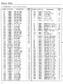
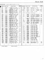
13. PARTS LIST — Chassis 120110B, 120113B.
SYMBOL
PART NO.
C-4
C-5
928006
928006
928006
928109
928006
910015
928006
928006
910015
9280O6
928006
910290
923062
928006
j 923062 ot
(922025
923062
923064
925161
923061
923062
910130
928006
928006
910031
928006
925161
910010
923079
923061
923061
j 923062 or
[922025
925162
923078
922101
Pt. of C-21
Pt. of C-29
Pt. of C-21
P.t. of C-29
928006
923067
923064
910028
910029
928006
Pt. of C-36
910027
923068
923080
910027
j 923062 or
1922025
910010
Pt. of C-29
910023
(923077 or
(922027
910017
923079
923067
923073
923003
j 923074 or
{922024
(923073 or
{922023
923064
923075
923O66
923078
923078
923085
923073
923073
Pt. of C-21
C-6
C-7
C-8
C-9
C-10
C-ll
C-12
C-13
C-14
C-15
C-16
C-17
C-18
C-19
C-20
C-21
C-22
C-23
024
C-25
C-26
C-27
C-28
C-29
C-30
C-31
C-33
C-34
C-35
C-36
C-37
C-38
C-39
C-40
C-41
C-42
C-43
C-44
C-45
C-46
C-47
C-48
C-49
C-50
C-51
C-52
C-53
C-54
C-55
C-56
C-57
C-58
C-59
C-60
C-61
C-62
C-63
C-64
C-65
C-66
C-67
C-68
C-69
C-70
C-71
C-72
C-73
C-74
22
DESCRIPTION
1,500 mmf, 400V
1,500 mmf, 400V
1,500 mmf, 400V
.005 mf, 400V
1,500 mmf, 4OOV
270 mmf, 400V
1,500 mmf, 400V
1,500 mmf, 400V
270 mmf, 4OOV
1,500 mmf, 400V
1,50O mmf, 400V
30 mmf, -+-10%
.05, 400V
1,500 mmf, 400V
.05 mf, 400V
.05 mf, 400V
.1 mf, 400V
10 mf, 450V
.01 mf, 4OOV
.05 mf, 400V
10 mmf, 400V
1,500 mmf, 400V
1,500 mmf, 400V
68 mmf, -+-20%
1,500 mmf, 400V
25 mf, 50V
110 mmf, -+-20%
.001 mf, 600V
.01 mf, 400V
.01 mf, 400V
.05 mf, 400V
80 mf, 250V
.005 mf, 400V
.05 mf, 400V
40 mf, 450V
40 mf, 450V
40 mf, 450V
40 mf, 450V
1,500 mmf, 400V
1 mf, 200V
.1 mf, 400V
220 mmf, -h!O%
150 mmf, -1-10%
1,500 mmf, 400V
80 mf, 250V
.001 mf, 500V
.05 mf, 200V
.25 mf, 200V
.001 mf, 500V
.05 mf, 400V
llOmmf, -+-10%
10 mf, 450V
780 mmf, 400V
.005 mf, 600V
470 mmf, 400V
.001 mf, 600V
.1 mf, 200V
.05 mf, 600V
.0005 mf, 10KV
.035 mf, 600V
.05 mf, 600V
.1 mf, 400V
.01 mf. 600V
.25 mf, 400V
.005 mf, 400V
.005 mf, 400V
.003 mf, 600V
.05 mf, 600V
.05 mf, 600V
25 mf, 50V
LIST
PRICE
SYMBOL
PART NO.
DESCRIPTION
.30
C-75
C-78
C--/9
C-80
C-bi
C-83
Pt. of C-36
910O90
900064
923O67
923062
Pt. of T-2
10 mf, 450V
50 mmf, 500V
3-35 mmf, Trimmer
.1 mf, 200V
.05 mf, 400V
75 mmf, 30OV
.30
.30
.30
.25
F-l
808050 or
808170
Fuse, !4A. 250V
Fuse |4A. 250V
.20
.35
M
708084
L-l
L-2
L-3
L-4
L-5
L-6
L-7
L-8{
708096
708097
708095
708095
705009
708082
708003
708130 or
708130-R
.30
.30
.35
.30
.25
.30
.30
.25
.30
.30
.25
.25
.30
.25
.35
.25
.30
4.60
.25
.25
.30
.30
.30
.20
.30
4.6O
.25
.25
.25
.25
.25
.35
4.60
.25
.30
.30
.30
.30
.30
.30
.30
.35
.25
.35
.35
.25
.35
.25
.35
.25
.35
.25
.25
.30
.30
1.50
.30
.35
.30
.35
.09
.25
.50
.25
.25
.25
.30
.30
L-9J
L-19
L-ll
L-12
708025
7O5014
737011
Ion Trap — P.M.
PRICE '
LIST
2.80
Peaking Coil — 75 uh
.45
Peaking Coil—45 uh -+-10%
.45
Peaking Coil — 180 uh
.50
Peaking Coil — IbO uh
.50
R.F. choke—3.0 mh ±10%
.60
Size coil
1.40
Linearity coil
1.50
Deflection yoke—Vert, coili 16.30
Deflection yoke—Horiz.
coils
Focus coil
7.OO
R.F. choke— 20 uh
Filter choke—6h
.45
4.15
P-3
5O5040 or
505048
505014
Connector plug—Speaker
Connector plug—Speaker
Plug — Interlock switch
.15
.15
.30
R-l
R-2
R-3
R-4
R-5
R-6
R-7
R-8
R-9
R-10
R-ll
R-12
R-13
R-14
R-15
R-16
R-17
R-18
R-19
R-20
R-21
R-22
R-23
R-24
R-25
R-26
R-27
R-28
R-29
R-30
R-31
R-32
R-33
R-34
R-35
R-36
R-3 7
R-38
R-39
R-40
R-41
R-42
R-43
R-44
340492
340492
340672
340212
340492
340492
340732
340652
340132
340492
340492
340632
340292
340492
341292
340652
341212
340932
Pt. of R-46
341212
330532
341212
340812
341072
341052
370632
370852
340892
341212
341032
340892
370812
370732
340492
340272
397014
397110
340972
340652
397014
340372
330972
340972
340932
1,000 ohm, y2vf, H-10%
1,000 ohm, y2w, ±10%
5,600 ohm, y2w, -1-10%
68 ohm, y2w, -+-10%
1,000 ohm, y2w, -1-10%
1,000 ohm, y2w, -+-10%
10,000 ohm, y2w, -+-10%
4,700 ohm, y2w, -+-10%
33 ohm, y2w, -+-10%
1,000 ohm, l/2w, ±10%.
1,000 ohm, y2w, ±10/o
3,900 ohm, ^w,±lO>o
.17
.17
.17
.14
.17
.17
.17
.17
.17
.17
.17
.17
.17
.17
.17
.17
.14
.14
P-2
150 ohm, y2w, -+-10%
1,OOO ohm, y2w, -l- 10%
2.2 megohm, y2w, -1-10%
4,700 ohm, l/2w, ±10%
1 megohm, y2w, ±10%
68,000 ohm, l/2w, ±10%
1,500 ohm, Contrast contro
1 megohm, y2w, -+-10%
1,500 ohm, y2w, ±5%
1 megohm, y2w, -+-1O%
22,OOO ohm, J/2w, ±10%
270,000 ohm, y2w, -1-10%
220,000 ohm, l/2v/, ±10%
3,900 ohm, Iw, -1-10%
33,000 ohm, Iw, +10%
47,000 ohm, y2w, ±10%
1 megohm, l/2vt, -+-10%
180,00 ohm, y2w, ±10%
47,000 ohm, y2w, -+-10%
22,000 ohm, Iw, ±10%
10,OOO ohm, Iw, -+-10%
1,OOO ohm, y2w, ±10%
120 ohm, l/2w, -1-10%
10,000 ohm, Iw, ±10%
4,700 ohm, 2w, -t-20%
100,000 ohm, y2w, -+-10%
4,700 ohm, y2w, -1-10%
10,000 ohm, 2w, +10%
330 ohm, y2w, -+-10%
100,000 ohm, l/2 w, ±5%
100,000 ohm, y2w, -+-10%
68,000 ohm, %v, + 10%
.14
.17
.14
.17
.14
.17
.16
.16
.17
.14
.14
.17
.16
.19
.17
.17
.20
.20
.17
.17
.20
.17
.14
.17
.14
Emerson Radio
PARTS LIST — Chassis 120110B, 120113 B. (cont.)
6
SYMBOL PART NO.
R-45
R-46
351492
390111
R-47
R-48
R-49
R-51
R-52
R-55
341132
341132
370492
341072
341132
39O106
R-61}
R-62{
R-63
R-64
R-65
R-66
R-67
R-68
R-69
R-70
R-71
R-72
R-73
R-74
R-75
R-76
R-78
R-79
R-80
394078
341212
330512
330492
330652
330572
397029
340892
341052
341052
330972
330972
37065(2
390075
340892
371132
371132
331132
390102
R-81
R-82
R-83
R-84
R-85
R-86
R-87
R-88
R-89
R-90
R-91
R-92
R-93
R-94
R-95
R-96
R-97
R-98
R-99
R-100
R-101
R-102
R-103
R-105
340792
341132
370252
397044
394O66
394007
340652
Pt. of R-75
371212
340812
340812
340652
370972
390112
331252
390038
341132
340712
341372
390039
340352
397043
390107
340432
R-77
"'Chassis 120110B
DESCRIPTION
15 megohm, J^w, -4-20%>
1 megohm, Volume Control
&. Switch
470,000 ohm, J^w, -4-10%
470,000 ohm, y2w, ±10%
1,000 ohm, Iw, -4-10%
270,000 ohm, y2w, -4-10%
470,000 ohm, ^w, ±10%
1,500 ohm, w.w., Focus control (rear)
8,000 ohm, w.w., lOw ± 10%
4,000 ohm, w.w., lOw, ±10%
1 megohm, J^w, -4-10%
1,200 ohm, y2w, -4-5%
1,000 ohm, y2w, -4-5%
4,700 ohm, J^w, -4-5%
2,200 ohm, y2w, +5%
100,000 ohm, 2w, -4-5%
47,000 ohm, y,w, -4-10%
220,000 ohm, ^w, -4-10%
220,000 ohm, y2v, -4-10%
100,000 ohm, y2v, -4-5%
100,000 ohm, y2w, -4-5%
4,700 ohm, Iw, ±10%
50,000 ohm, Hor. Hold cont.
47,000 ohm, y2w, -4-10%
470,000 ohm, Iw, -4-10%
470,000 ohm, Iw, -4-lO%
470,000 ohm, y2w, -4-5%
20,000 ohm, Hor. Drive control
18,000 ohm, yzvr, -1-10%
470,000 ohm, J&w, -4-10%
100 ohm, Iw, -4-10%
10,000 ohm, 4w, -4-10%
3.3 ohm w.w., ^w, -4-10%
7,500 ohm, w.w., 25w. -4-5%
4.700 ohm, y2w, -4-10%
100.000 ohm, Brightness cont.
1 megohm, Iw, -4-10%
22,000 ohm, J^w, -4-10%
22.000 ohm, y2vt, '-+-10%
4,700 ohm, y2vt, -4-10%
300,000 ohm, Iw, -4-10%
1 megohm, Vert. Hold cont.
1 .5 megohm, J/2vf,
-4-5%
2 megohm. Vert. Size nnt.
470.000 ohm. */2w, -4-10%
8.200 ohm, y2v/, ±10%
4.7 megohm. y2w, -4-10%
5.000 ohm. Vert. Lin. cont.
270 ohm. y2w, -4-10%
10.000 ohm, 3w, ±10%
^0 ohm. Horiz. Cent. cont.
560 ohm, y2w, -4-10%
PRICE
LIST
.14
3.85
.17
.17
.16
.14
.17
2.30
1.55
.14
.14
.17
.14
.17
.55
.17
.17
.17
.14
.14
. 16
2.20
.17
.16
.16
.14
.90
.14
.17
.19
.85
.10
1.25
.17
.16
.17
.17
.17
.16
.95
.17
.85
.17
.14
.14
1.75
.14
.30
1.5O
.14
SYMBOL PART NO.
DESCRIPTION
R-106
R-108
340432
340572
560 ohm, y2w, ±10%
2,200 ohm, J4w, -4-10%
Tuner*
Tuner #
470452
470604
Tuner Assy. — Standard
Tuner Assy. — Standard
SP-1
180047
Speaker — 6" P.M.
SW-1
Pt. of R-46
T-l
T-2
T-3
T-4
T-5
720056
720042
720109
720057
720081
T-6
708O17 or
708018
734051
738008
738028
738004
738026 or
738026a or
738027
730018
T-7
T-8
T-9
T-10
T-ll
T-12
V-12
V-13
V-14
V-15
V-16
V-17
V-18
V-19
V-25*
V-25#
V-27
V-28
V-29
X-l
X-2
X-3
470232
508010
583206
Socket —Cable assembly
Socket— Speaker
Socket— Interlock switch
V-10
V-ll
50.00
50.00
6.00
1st video I.F. transformer
1.90
2nd video I.F. transformer
2.45
3rd video I.F. transformer
.90
4th video I.F. transformer
1.90
Sound I.F. transformer —
1.75
4.5 me.
Discriminator coil— 4.5 me.
4.10
Discriminator coil—4.5 me.
3.35
1.40
Sound output transformer
Horiz. oscillator transformer 3.00
11.40
Horiz. output transformer
5.50
Vert, oscillator transformer
5.70
Vert, output transformer
5.70
Vert, output transformer
Vert, outpu; transformer
30.00
Power transformer
Vacuum tube, 6AG5
Vacuum tube, 6AG5
Vacuum tube, 6AU6
Vacuum tube, 6AL5
Vacuum tube, 6AU5
Vacuum tube, 12AU7
Vacuum tube, 6ALJ6
Vacuum tube, 6AU5
VacuuTi tube, 6T8
Vacuum .ube, 6V6GT
Vacuum tube, 6SN7GT
Vacuum tube, 6AL5
Vacuum tube, 6SN7GT
Vacuum tube, 6SN7GT
Vacuum tube, 12AU7
Vacuum tube, 6K'>GT
Vacuum tube, 6BG6G
Vacuum tube, 183-GT/0016
Vacuum tube, 6W4-GT
Kinescope, 10BP4
Kinescope, 12LP4
Vacuum tube, 6J6
Vacuum tube, 6AG5
Vacuum tube, 5U4-G
V-8
V-9
.14
.14
On-of f Switch
800535
800535
800533
800541
800533
800026
800533
800533
800035
£00270
800380
800541
800380
800380
800026
800016
80O004
80O450
800037
810000
810003
800536
80O535
800290
V-l
V-2
V-3
V-4
V-5
V-6
V-7
PRICE
LIST
3.05
.20
1.00
#Chassis 120113B
23
Radio and
Television
CABLE
RADIO
ADDRESS
AND
EMPHONOCO
NEW
YORK
PHONOGRAPH
111 EIGHTH AVENUE §™"J
CODES:
BENTLEYS
ABC
CORPORATION
NEW Y O R K C | T Y
]]
January 30,1950
TO ALL aiERSON TEI£VISIQN DISTRIBUTORS i
Field Service Bulletin #5
Subject: Changes in Model 6U8 Chassis 120110E
Chassis coded with Triangle 1 incorporate the following changes
to improve vertical linearity*
1. R98 changed to 1 Beg. \.
2. R106 has been transferred from the lug where R86 is tied,
to the fl plus point on the terminal strip near the 3rd I.F.
3. R6? has been transferred from the junction of R60 and R90
to the B plus point on terminal strip near VI.
U. Resistor R60 has been transferred from the B plus point
on terminal strip near Tube VI to the B sinus point of the
terminal strip near Tube Vllu
5. Resistor R61* has been transferred from the B minus point
on terminal stip near vlU to the junction of R60 and R90
on the terminal strip near the 2nd I.F.
The suffix letter "C" added to the Triangle 1 code indicates the
use of electrolytic condenser part #925165 in place of #925l62«
The terminal markings of these condensers are as follows s
#925162
80 mfd. - 250 V DC
80 mfd. - 250 V DC
10 mfd. - U50 V DC
#925165
CD
Very truly yours,
EMEKSON RADIO & PHOHOQR1PH CORPORATION
OCiVA
George Cohen
General Manager of Parts
Sales & Service Division
A G R E E M E N T S AND S A L E S SUBJECT TO S T R I K E S . A C C I D E N T S OR OTHER C A U S E S B E Y O N D OUR
CONTROL
5TH
EDITION IMP
IE
CHELSEA
2-lfloO
CABLE
A D D R E S S .
EMPHONOCO
NEW
YORK
CODES
B E N T L t Y S
ABC
5TH
EDITluN
I mP
Tftnerson
RADIO
AND
PHONOGRAPH
111 EIGHTH AVENUE If
A
CORPORATION
1 NEW YORK CITY, 1 1
December 28, 1949
TO ALL EMERSON TELEVISION DISTRIBUTORSt
Field Service Bulletin #1
Subject!
ict
Revision to eliminate picture
flutter caused
by line voltage variatj on.
f
Models 614C, 637C, 644C, 647C using chassis 1201 IOC and 120113C having
triangle codes 1 and 2. (Sets already manufactured incorporating this
change will be identified by code triangle 3.)
Modeli 614B, 637B, 644B, 647B using chassis 12011OB and 120113B having
triangle code number 8.
1.
Cut wire between triangle lug andsquare lug of C-41, part #925166.
2.
Remove lead (blue) from pin #6 of 6AU6 first video amplifier going
to the triangle lug of C21. Strip end of this (blue) lead and connect
to the last empty lug on the terminal strip near C21.
3.
Cut one end of R21 — 1500 ohm irom pin #6 and extend this resistor to
the same lug of terminal strip near C21 in step #2.
4.
From this »n» empty lug, run a jumper lead, approximately 16" long to
another empty lug on the terminal strip near the 6W4. On this new
terminal lug, connect a 10K, 1 watt resistor to the junction of the
3300 ohm, 1 watt, R-102 and the resistor 7500 ohm, R86.
(Boostered B
plus point.)
5.
Connect pin #6 of the 6AU6 first video amplifier to the square of C41.
6.
Replace .047, C-19 kinescope coupling with a .01 mf. condenser (400V).
Models 614B, 637B, 644B, 647B using chassis 120110B and 120113B having
triangle codes 1, 4 and 5.
1.
Remove 33K, 1 watt between pin #6 of V-5 and terminal board and replace
with a 10K, 1 watt resistor.
2.
Remove all connections from pin #6 of V-5, 6AU6 leaving all connections
intact but away from pin #6 (blue lead, 10K, 1500 ohm).
3.
Connect a jumper wire from pin #6 of V-5 to C-41 (square terminal electrolytic),
4.
Connect a jumper wire (16") from junction of lug on terminal board and
10K ohm resistor from step #1 to junction of the damper resistor
AGREEMENTS AND SALES SUBJECT TO S T R I K E S . ACCIDENTS OR OTHER
CAUSES
BEYOND OUR
CONTROL
HONE
CHELSEA
2.ISOO
CABLE
A D D R E S S .
EMPHONOCO
NEW
YORK
COOES
BENTLEYS
ABC
5TM
'EDITION
Jynerson
RADIO
AND
PHONOGRAPH
111 EIGHTH AVENUE ff
CORPORATION
\W Y O R K CITY, 1 1
September 13, I9k9
TO ALL EMERSON DISTRIBUTORS;
In order to keep you advised of circuit changes in Emerson Television
Receivers, a simple code identifying system has been put into effect.
A triangle with a number inside it will be inked on the rear wall of
the chassis next to the AC power input.
Each time any change is made in production, the number within the
triangle will change and, automatically, a field service bulletin will
be issued to you so that you may keep up to date on all such circuit
changes.
It is also important that you keep a record of these changes and file
them properly for future reference.
This bulletin is the first in this new series and pertains to the Model
637 chassis model 110. Chassis bearing the code Triangle 1 have the
following revisions incorporated:
Circuit Revisions to Correct Picture FLICKER or BOUNCE
1. Remove red lead from the B plus 125 volt point on terminal strip
near hth I.F. and from Pin #6 of the 6AU6 (V-5).
2. Remove red lead from the r—i terminal of C-U2 and from Pin #6
of the 6AU6 (V-5).
3. Insert a wire between the B plus 125 volt point and the *—*
of the C-U2 above.
terminal
ii. Remove the Ii7,000 ohm resistor (R-28) from Pin #6AU6 (V-5) then wire it
to the B plus 125 point on terminal strip near the ij.th I.F.
5. Remove the 33,000 ohm resistor (R-2?) from the B plus 125 volt point
on terminal strip near V-12 and V-13 and from the junction of toe blue
lead ^ C-21 on terminal strip near V-6 and V-l5»
6. Wire the 33,000 ohm resistor (R-2?) between Pin 6 of 6AU6 (V-5) and the
empty lug on terminal strip near the power transformer. Add a wire from
AGREEMENTS AND SALES SUBJECT TO S T R I K E S .
ACCIDENTS OR OTHER CAUSES BEYOND
OUR
CONTROL
IMP
"Emerson Radio
ADDENDUM SERVICE NOTE
TELEVISION RECEIVERS
MODELS 614, 637, 644, and 647
CHASSIS MODELS 1201 IOC and 1201 I3C
I.
GENERAL
The mode's listed have been revised both mechanically and electrically. The major mechanical change is the conversion
to two dual-controls in plnce of the original arrangement of four dual-controls. Such models and chassis are identified by
the subscript C or BC, as for example Model 644C. The major electrical change is the use of a multivibrator circuit in place
of a blocking oscillator, in the vertical deflection circuits. This revision applies to both B and C chassis.
The change in the arrangement of operating controls is illustrated in figure 1. The Vertical Hold control, and Brightness
and Horizontal Hold controls, are located at the rear of the chassis, as shown in figure 2. Mechanical centering is provided by
i-se of a movable focus coil controlled by a lever. The centering lever may be tilted both up and down, and side to side.
HORIZONTAL HOLD CONTROL:
STOPS HORIZONTAL MOTION
OF PICTURE
O CONTRAST
•OFF-VOLUME
,
3RIGHTNESS CONTROL
\S PICTURE
\ A V E R A G E BRIGHTNESS.
REAR CONTROLS
HOR.
SIZE
0
LCONTRAST
CONTROL:
ADJUSTS PICTURE CONTRAST,
LIGHT OR DARK.
INDICATOR CONTROL:—'
SELECTS STATIONS.
1
\R
HOR.
LIN.
0
O
O
O
O O\
Fig. 2—Rear Adjustment Controls
FINE TUNING CONTROL.
ADJUSTS RECEIVER
FOR BEST PICTURE.
-OFF-VOLUME CONTROL;
TURNS RECEIVER ON 3
ADJUSTS SOUND VOLUME
Fig. 1—Operating Controls
2.
VERTICAL
MULTIVIBRATOR
Chassis code marking Triangle 6, stamped at the rear of chassis 120110B or 120113B, includes the change of the vertical
sweep generator to the multivibrator type, with an auto-transformer in the output circuit. This revision is indicated in the
schematic diagram, figure 3. All previous modifications, listed in the present service manual, are included.
3.
MECHANICAL CENTERING
Use of mechanical centering controlled by the ''wobble'' plate and focus coil lever (picture centering lever) is indicated by
code marking Triangle 7. The Huri/ontal Centering control, R-105, part no. 390107, is replaced by a 10 ohm, \-> watt
resistor.
4.
BC and C TYPE CHASSIS
Mechanical revision of chassis 1201 10B and 120113B, to provide for the control arrangement previously outlined, resulted in chassis 1201 IOC and 120115C. Note that the code markings applicable to the C-type chassis differ from those assigned
to the B-type chassis. Chassis marked BC are identical in control arrangement with C chassis but make use of extension brackets
for several controls.
5.
TUNER REVISIONS
The "Standard" turret tuner, part no. 47060?, originally used in the models listed, has been modified as to shaft length,
and becomes part no. 470607, Tin- C-typo chassis may use an alternate tuner, part no. 470605, produced by "Automatic.'*
Such chassis are identified by code m a r k i n g Triangle O. No circuit modifications are entailed; however, the arrangement and
locatton of a l i g n m e n t trimmers and oscillator slugs differs, as shown in figure 4.
EMERSON RADIO & PHONOGRAPH CORPORATION
1 1 1 EIGHTH AVENUE
NEW YORK I I, N. Y.
VE
SOUND - I f
V-7
»Mf>
6AU6
SOUND DIS
» AUDIO A
SOUND - I F L I W I T E R
V-8
6AU6
V-9
BUILT-IN
DIPOLE «NT.
r/i;.
J—Sflictnatii'
6T8
SOUND DISCR
AUDIO AMI-.
CHASSIS NO. I Z O I I 3 - C
\-VERT.MOLO
'—VERT, LINEARITy
PART NO. 950129-R <»««•*
rain—Chassis 12011 }C
Fig. 4—Automatic Tuner—Part No. 470605
6.
PICTURE TEAR
Code markings, Triangle 8, on B series chassis, and Triangle 1 on C series chassis refer to the same circuit modifications to
eliminate picture tear. These markings include all previous revisions, plus the following circuit changes:
7.
a.
Removed R-27 (33K, 1 watt).
b.
Connected pin 6 of V-5 (screen) directly to B-j- (output side of filter choke connected to C-41, 40 mfd.,
marked Q).
c.
Replaced R-25 (220K) with 1 megohm, l/z watt resistor.
d.
Removed lead between pin 4 of V-10 (screen) and junction of L-13, C-31, C-36, and low end of R-46 (Vol.
control).
e.
Disconnected L-13 from junction point (L-13, C-31, etc.) and rewired to pin 4 of V-10.
f.
Added jumper wire between junction point (L-13, C-31, etc.) and pin 7 of V-9 (cathode).
PARTS LIST
The parts list included in this addendum note tabulates those components whose values have been changed as a result of
the foregoing modifications, plus new components added to the original circuit.
SYMBOL
C-32
C-37
C-68
C-69
C-70
C-71
C-72
C-73
C-74
R-7
R-25
R-50
R-90
PART No.
928006
923088
923088
923079
923079
922014
922024
910027
Pt. of C-21
340732
341212.
.340272
340732
DESCRIPTION
1500 mmf., 400v
.002 mf., 600v
.002 mf., 600v
.001 mf., 600 v
.001 mf., 600v
.1 mf., 200v
.033 mf., 60Ov
.001 mf., mica, 500v
10O mf., elect., lOOv
10,000 ohm, '/2w, ±10%
I megohm, }4w, -t-10%
120 ohm, J.jw, -t-10%
10,000 ohm, ]Avt, -4-10%
SYMBOL
R-94
R-95
R-96
R-97
R-98
R-99
R-100
R-101
R-102
R-103
T-ll
Tuner
PART No.
340972
390132
340872
340572
331392
390138
390135
370612
370612
240012
738029
470605
DESCRIPTION
100,000 ohm, J.jw, ±10%
100,000 ohm, Vert. Hold control
39,000 ohm, s/>w, ±-10%
2,200 ohm, l/2v, ±10%
5.6 megohn, *4w, --4-10%
3 megohm, Vert. Size control
3,000 ohm, Vert. Lin. control
3,300 ohm, Iw, ±10%
3,300 ohm, Iw, ±10%
10 ohm, y2vt, ±10%
Vert, output trans.
Tuner ass'y.— Automatic
For best results replacements should be made with genuine Emerson parts and genuine Emerson tubes.
FOR REPLACEMENT PARTS — SEE YOUR NEAREST EMERSON DISTRIBUTOR OR WRITE DIRECTLY TO
EMERSON RADIO & PHONOGRAPH CORPORATION
1 1 1 EIGHTH AVENUE
NEW YORK II, N. Y.. U. S. A.
8-241049-JiM
HELSCA
2-ISOO
CABLE
ADORE**:
EMPHONOCO
NEW
YORK
COOES:
BENTLETS
ABC
STM
EDITION
I
'Emerson
RADIO
AND
PHONOGRAPH
111 EIGHTH AVENUE
CORPORATION
NEW Y O R K C I T Y , 11
December 16, 1949
Additions to Service Han.ual. Section 10. Production Changes HOB & 113B Chassis
Triangle 6
Identifying receivers with built-in antenna, improved mechanical focus with wobble
plate and included are revisions issued under Code notices Triangle 4 and Triangle 1,
1. Replace the jumper wire between cathode (lug 7) of V-9 and terminal board
with R.P. choke, part #925002 between cathode (lug 7) of V-9 and chassis.
%, Insert a 1500 mmfd. condenser, part #928006, between cathode (lug 7) of V-9
and ohassia.
Kgioent_ Product ion Change on 12011QC and 12.Q115C Chassis
£
Identifying Receivers With Circuit Modification To Improve.. .Interlace and Vertical
Jitter
Parts to be changed.
1. Change R-96 from 39K to 68K.
2. Change R-93 from 100K ohms to 47K ohms.
3. Change C-70 from .001 mfd. to .005 mf.
Circuit
1. Transfer yellow wire from dummy lug strip near vertical blocking transformer,
junction of R63, R64, R65, R93 and R97 to junction of C51, C61 and C68.
2. Remove yellow wire from the same dummy lug strip, junction of C51, C68, C61
and electrolytic can.
3. Add new yellow wire between same dummy lug at junction of R63, R64, R65, R93,
R97, to electrolytic can C29, near V-4, 6AI.5 socket.
4. Transfer lead of C68, .002 mfd. 600 volt condenser from same dummy lug,
junction of C51, C61, C68, to junction of R63, R64, R93 and R97.
The following
R-51
R-82
R-26
R-92
R-93
C-67
Parta To The Addendum Parts List
341132
470,000 ohm, carbon, $ watt +/- 10%
341072
270,000 ohm, carbon, i watt +/- 10%
397039
3,900 ohm, carbon, 2 watt +/- 10%
340872
39,000 ohm, carbon, \t +/- 10%
340892
47,000 ohm, carbon, \t +/- lOjC
923088
.002 mf . , paper, +/- 20%, 600 volt
Add The Following Corrections To The Addendum Parts; List
R-96
340932
68,000 ohm, carbon, i watt +/- 10%
C-70
923110
.005 mf., paper, +/- 10%, 600 volts
In service note for 614, 637, 644, 647 page 20, item K, this should read vertical
output transformer, (T-ll) instead of horizontal output transformer (T-9).
AGREEMENTS AND SALES SUBJECT TO STRIKES. ACCIDENTS OR OTHER CAUSES BEYOND OUR CONTROl