1
OPERATING AND SERVICE MANUAL
(HP
PART
NO. 00461-90002)
MODEL 461A/462A
WIDEBAND AMPLIFIER
SERIALS
PREFIXED:
606- (461A)
551- (462A)
Appendix C, Manual Backdating Changes,
adapts manual to Serials Prefixed:
418-, 346- (461A)
421-, 414-, and 347- (462A)
Copyright Hewlett-Packard Company 1963
P. O. Box 301, Loveland, Colorado, 80537 U. S. A.
01358-3
Printed:
AUG 1966
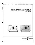
Section I
Figure 1-1
Models 461A/462A
""
IIiPUT
•
•
Model 461A
Wide Band Amplifier
IKC'150MC
J
....
~ :::.~~
Wide Band Amplifier
$Allt lotll
Off.
Model 462A
~Ofl
INP'OT
N
oW
•
( '/
s
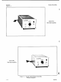
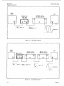
Figure 1-1. Hewlett-Packard Model 461A/462A
Wideband Amplifier
1-0
01358-1
Section I
Paragraphs 1-1 to 1-5 and Table 1-1
Models 461A/462A
SECTION
GENERAL
1-1.
I
INFORMATION
GENERAL INFORMATION.
1-2. The -hp- Models 461Aand462A Wide Band Amplifiers can faithfully amplify both sinusoidal and complex signals in the 1 KHz to 150 MHz range. The Model
461A is best suited for sinusoidal inputs, and the Model
462A is designed for complex and pulse inputs. The
Model 461A frequency response is ±1 db from 1 KHz
to 150 MHz. The Model 462A rise and fall times are
less than 4 nanoseconds. Either 40 db or 20 db gain
can be selected with the front panel GAIN (DBswitch.
The Models 461A and 462A are shown in Figure 1-1.
The specifications of both instruments are given in
Table 1-1.
1-3. Since the Models 461A and 462Aarenearlyidentical, this manual wlll discuss the instruments in terms
of the Model 461A. The Model 462A will be mentioned
only when its operation differs from that of the Model
461A.
1-4.
ACCESSORIES AVAILABLE.
1-5. The -hp- 11048A 50-ohm feedthrough termination is an available accessory that is connected at
the output of the Model 461A. The feedthrough termination should be used to ensure that the Model 461A
is operating into its rated impedance in the event
the instrument is connected to a device with an impedance greater than 50 ohms.
Table 1-1. Specifications
MODEL 461A
Pulse Duration for 10% Droop: 30 usee.
Frequency Range: 1 KHz to 150 MHz
Frequency Response: ±1 db. 1 KHz to 150
MHz, when operating into a 50-ohm resistive load (500 KHz reference).
Output: 1 volt peak-to-peak into 50-ohm
load.
Delay: Nominally 12-14 nanoseconds.
GENERAL (461A and 462A)
Gain at 500 KHz: 40 db ±G. 5 db; or 20 db ±1.0
db, selected by front panel switch. Output
is inverted with respect to input.
(1-
Maximum Input: 1 volt rms or 2 v p-to-p,
Output: O. 5 ±{} u- ,.lts rms into 50-ohm
resistive load.
Maximum DC Input: ±2 volts.
Overload Recovery: Less than 1 flsec for 10
times overload.
Distortion: Less than 5% at maximum output
and rated load.
Equiva lent Input Noise Level: Less than 40
Vt·
MODEL 462A
Pulse Response:
Rise and Fall Time: Less than 4 nanoseconds.
Over and Undershoot: Less than 5%.
Gain: 40 db or 20 db selected by front
panel switch. Output is inverted with
respect to input.
01358-3
microvolts in 40 db posilion.
Input Impedance: 50 ohms, nominal.
Power Supply: 115 or 230 v ±10%, 50 to
1000 hertz. 5 watts.
Dimensions: 3-14/32" (8.7 em) wide x 11"
(27. 9 em) long.
Weight: Net: 4 Ibs (1. 8 Kg). Shipping: 6
Ibs (2. 7 Kg).
Accessory Furnished: Detachable Power Cord
Accessory Available: -hp- 11048A 50-ohm
through termination.
1-1
Section III
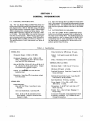
Figure 3-1
Models 461A/462A
rf;;o.,
W
46lA AMPLIFIER
IlEWLETT • PACKARO
o
GAIN(DB)
OFF 20 40
0]
OUTPUT
I;)
2VCMAX
r v CMAX
[0
eon.
50it
INPUT
IKC-150MC
e
2
CD GAIN (DB) switch: Applies primary power and
o
selects gain.
50 n INPUT connector: Connects input signal
to the instrument. DO NOT APPLY MORE
THAN 1 VAC OR 2 VDC TO INPUT.
CD output
50 n OUTPUT connector: Connects amplified
to load. Output must be terminated in 50
n. VOLTAGE LEVELAT OUTPUT MUST NOT
EXCEED -6 VOLTS DC OR +0. 6 VOLTS DC.
Figure 3-1.
3-0
o
AC POWER connector: Connects primary power
to the instrument.
CD LINE VOLTAGE:
Selects either 115 volts ac
or 230 volts ac primary power.
CD fuse
Fuseholder: Contains a 1/4 ampere fast-blow
for both 115 and 230 volt operation.
Front and Rear Panel Description
01358-1
------------
Models 461A/462A
Section ill
Paragraphs 3-1 to 3-10 and Figure 3-2
SECTION III
OPERATING INSTRUCTIONS
3-7. IMPEDANCE MATCHING.
3-1. INTRODUCTION.
3-2. The Model 461A can be used to faithfully amplify
signals in the I KHz to 150 MHz range. Gain settings
of 20 db or 40 db may be selected with the front panel
GAIN (DB) switch. The Model 461A will operate within
specifications only when its output is terminated in 50
ohms.
3-3. FRONT AND REAR PANEL
DESCRIPTION.
3-4. Figure 3-1 describes the function of all the controls and indicators on both the front and rear panel.
3-5. OPERATING INSTRUCTIONS.
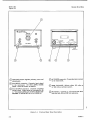
3-6. Figure 3-2 contains the operating instructions
for the Model 461A. Each instruction is keyed to a
drawing of the front panel.
SIGNAL SOURCE
3-8. Both the input impedance and the output impedance of the Model 461A are 50 ohms. The Model
461A output must be connected to a 50 n load if it is
to operate within specifications. If the input impedance
of the load is not 50 n, a terminating impedance of 50
n must be connected across the Model 461A output.
The -hp- Model 1l048A 50 n Feedthrough -Termination
is recommended for this purpose. The Modelll048A
may be easily connected in series with the Model 461A
output.
3-9. CASCADING AMPLIFIERS.
3-10. The Model 461A will amplify small signals in
the 5to 50 millivolt range to an amplitude of O. 5 volts
with minimum distortion. Should larger output signals
be desired, the Model 461A can be cascaded with other
amplifiers, such as the -hp- Models 460A and 460B.
Typical set-ups cascading the Model 461A and Models
460A and 460B are shown in Figures 3-3 and 3-4.
hp 461A
WIDE BAND
AMPLIFIER
LOAD
DO NOT APPLY MORE THAN I VAC OR 2 VDC TO INPUT
TERMINALS. VOLTAGE LEVEL AT OUTPUT MUST NOT
EXCEED -6 VOLTS DC OR +0. 6 VOLTS DC.
CD Connect the I KHz to 150 MHz frequency source
to the input of the Model 461A.
f2\ Connect the output of the Model 461A to a 50\:..J
ohm load. Theinstrumentwlllbewithinspecifications only if connected to a 50-ohm load.
Set Power and Gain Switch to the desired gain
setting (20 or 40 db).
CD
NOTE
The maximum output voltage obtainable
from the Model 461A is O. 5 volts rms
(I VoltP-PforModeI462A). Thus the
maximum Input voltage that can be appiled, without distortion, is 50mvon the
20dbrange, and 5mvonthe 40 db range.
Figure 3-2. Operating Instructions
01358-2
3-1
Section III
Figures 3-3 and 3-4
Models 461A/462A
SIGNAL
SOURCE
LOAD
~ MODEL 460AR
WIDE BAND AMPLIFIER
~MODEL 461A
WIDE BAND
AMPLIFIER
INPUT
~
OUTPUT
i»
='5JJi.. =
o
~-0ill1 ~.5V
5MV P-P
P-P
Figure 3-3. Cascading Amplifier
SIGNAL
SOURCE
~MODEL 461A
WIDE BAND AMPLIFIER
OUTPUT
~NPUT !050UTM)
LOAD
~MODEL 460AR
~MODEL 460BR
WIDE BAND AMPLIFIER
WIDE BAND AMPLIFIER
INCi)
OU/~UT
OU{5UT
1N(i)
c
INPUT
(i:J)
4~IA/4~1A·a·l
=1'ffiL -= :: I MV P-P ='Il1J= =100 MV P-P
!Il~ ~I
VOLT
P-P
TJJ--
5 VOLTS P-P
---
---
Figure 3-4. Cascading Amplifier
3-2
01358-2
Models 461A/462A
Section IV
Paragraphs 4-1 to 4-8
SECTION
THEORY
OF
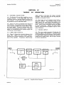
4-1. GENERAL DESCRIPTION.
4-6. Each stage has an LR feedback circuit with an
adjustable inductor. The feedback circuit in each
stage controls the overall gain of the amplifier at a
differentfrequency, so the amplifier must be staggertuned. There is some interaction between the stages
at certain frequencies. A3Q9 is the output emitter
follower, and it matches the amplifier output to a 50 Q
output impedance.
4-3. Figure 4-1 shows a simplified block diagram of
the Model 461A. The amplifier is afive stage, staggertuned, cascaded amplifier with emitter follower input
and output stages. The gain is switched from 40 db
to 20 db by attenuating the input by 20 db. The power
supply is a conventional series regulated supply with
+15 volt and -15 volt outputs.
4-7. POWER SUPPLY.
4-8. The power supply generates +15 volts and -15
volts bias supply to the amplifiers. Breakdown diode
A2CR3 establishes a 15volt reference. Control transistor A2Q2 detects differences between the reference
voltage and the supply output, and its output controls
the series regulator Ql.
4-4. AMPLIFIER CIRCUITS.
4-5. Figure 5-13 shows the schematic diagram of the
Model 46lA. A3Q3 is the input emitter follower,
matching the 50 Q input impedance to the input impedance of the amplifier. Transistors A3Q4 through
,
-
>
ATTENUATOR
AI
"#
EMITTER
FOLLOWER
Q3
OPERATION
A3Q8 constitute a five stage, RC coupled, cascaded
amplifier. Each stage has a gain of 8 db, giving the
amplifier a total gain of 40 db.
4-2. The Models 461A and 462A Amplifiers are essentially identical. In the Model 462A some of the
component values are changed slightly to improve its
pulse response. In this section both instruments will
be presented in terms of the Model 461A.
I INPUT!
IV
........
IOUTPUT I
AMPLIFIERS
f-
Q4-Q8
EMITTER
FOLLOWER
Q9
.J;
(
/
/
q
/
PRIMARY
POWER
GAIN
SWITCH
I
a
51,53
\
\
\
SERIES
PRIMARY
REGULATED
POWER
POWER SUPPLY
QI-Q3
46IA/462A-B-9
Figure 4-1.
01358-2
Simplified Block Diagram
4-1
-- -------
-----------------------------------------------------
Section V
Table 5-1
Models 461A/462A
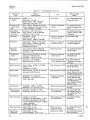
Table 5-1. Test Equipment Required
Instrument
Type
Critical
Specifications
Use
Recommended
Model
Wide Range Oscillator
Output: 3v
Impedance: 50 ohms
Freq.Range: 5 Hz - 500 KHz
Distortion: less than O. 5%
Gain Check
-hp- Model 200SR Wide
Range Oscillator
Frequency Respouse Test
Set
Freq. Range: 500 KHz to 10 MHz
Freq. Response: Flat within +0. 5% 1. 5%, 500 KHz to 10 MHz
Frequency Response
Check
-hp- Model 739A Frequency Response Test
Set
Logarithmic
Vacuum Tube
Voltmeter
Accuracy: ±I% at full scale
Freq. Range: 10 Hz to 500 KHz
DB Range: -60 to +10 db
Gain Check
-hp- Model 400L Logarithmic Vacuum Tube
Voltmeter
Attenuator
Attenuation: 40 db
Accuracy: ±O. I db
Freq. Range: I KHz to 150 MHz
Frequency Response
and Gain Check
Weinschel 50-40S
Attenuator
Attenuation: 120 db in 10 db steps
Freq. Range: I KHz to 150 MHz
Overall Accuracy: ±1. 5 db
Impedance: 50 ohms
Frequency Response
and Gain Check
-hp- Model 355D VHF
Distortion
Analyzer
Freq. Range: 20 Hz to 500 KHz
Sensitivity: Measure 5% distortion
Accuracy: ±3%
Distortion Check
-hp- Model 331A Distortion Analyzer
RF Millivoltmeter
Freq. Range: 500 KHz to 150 MHz
Accuracy: ±6% full scale
DB Range: -30 db to +10 db
Frequency Response
Noise Check
-hp- Model 411A RF
MillIvoltmeter
Multlmeter
Accuracy: ±I% full scale
Input Resistance: 200 M n
Troubleshooting and
-hp- Model 412A DC
Power Supply Checks
Voltmeter-OhmmeterAmmeter
Signal Generator
Freq. Range: 10 MHz - 150 MHz
Output: 0.5 v
Impedance: 50 ohms
High Frequency Check -hp- Model 608C/D VHF
Signal Generator
Power Meter
Power Range: -30 dbm to +10 dbm
Accuracy: ±3% full scale
Oscilloscope
Bandwidth: Dc to 200 KHz
Sensitivity: 10 mv/cm to 10 v/cm
Type: dual trace
High Frequency Check -hp- Model 431A/B
Power Meter with -hp478A ThermistorMount
Frequency Response
-hp- Model 122A Dual
Calibration
Track 200 Kc Osc11loscope or - hp- Model
175 Oscilloscope
- hp- 1750A and 1780A
Plug-in units
Oscilloscope
Bandwidth: I KHz to 50 MHz
Sensitivity: O. I v/cm to I v/cm
Pulse Response Check -hp- Model 175A Osc11loscope
High Frequency
Oscilloscope
Bandwidth: 50 MHz to I GHz
Sensitivity: 200 mv/cm to 5 v/cm
Pulse Response Check - hp- Model 185B 100
and Calibration
Mc Oscilloscope with
-hp- 187B Dual Trace
Amplifier
Pulse Generator
Impedance: 50 ohms
Leading and Trailing Edge: <1 nsec
Overshoot and Ringing: <5% peak
Corner Rounding Amplitude: <95% of
pulse amplitude
Pulse Width: 30 nsec
Pulse Response Check - hp- Model 215 Pulse
and Calibration
Generator
Pulse Generator
Pulse Width: 1 uee«
Pulse Amplitude: 0.5 v, p-p
Pulse Overload
Recovery Check
- hp- Model 212A Pulse
Pulse Width: 30 usee
Pulse Amplitude: 0.01 v, p-p
Pulse Decay Check
-hp- Model 211A Square
Wave Generator
Square Wave
Generator
5-0
Coaxial Attenuator
Generator
01358-2