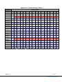
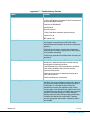
1
User’s Manual The most important thing we build is trust. Messenger VETA Receiver Decoder (MVRD) 100-M0145X2 06/10/2010 Cobham Surveillance GMS Products 1916 Palomar Oaks Way Ste 100 Carlsbad, CA 92008 T: 760-496-0055 F: 760-496-0057 www.cobham.com/gms Table of Contents 1. Acronyms ......................................................................................................................................................................................... 5 2. Introduction .................................................................................................................................................................................. 6 2.1 2.2 2.3 About the Manual ...................................................................................................................................................................... 6 Warranty ......................................................................................................................................................................................... 6 Safe Operating Procedures .................................................................................................................................................... 7 3. General System Information ............................................................................................................................................. 8 3.1 3.2 Product Control & Status Monitoring Approach ......................................................................................................... 8 Understanding Configurations............................................................................................................................................. 9 4. MVRD Local Control .............................................................................................................................................................. 10 4.1 Introduction ................................................................................................................................................................................10 4.2 Main Display ...............................................................................................................................................................................10 4.2.1 Main TS screen .................................................................................................................................................................10 4.2.2 Main RF screen .................................................................................................................................................................12 4.3 Status Menu ................................................................................................................................................................................12 4.3.1 Signal Strength .................................................................................................................................................................12 4.3.2 Decoder Status .................................................................................................................................................................14 4.3.3 LAN IP ADDRS Status Display....................................................................................................................................14 4.3.4 Genlock Locked ................................................................................................................................................................14 4.3.5 Number of Programs......................................................................................................................................................14 4.3.6 Selected Program ............................................................................................................................................................14 4.4 Setup Menu .................................................................................................................................................................................14 4.5 Receiver Setup ...........................................................................................................................................................................15 4.5.1 RX Input Source ...............................................................................................................................................................15 4.5.2 RX Configuration .............................................................................................................................................................16 4.5.3 OSD Control .......................................................................................................................................................................16 4.5.4 RF Input Freq .....................................................................................................................................................................16 4.6 Genlock Setup ............................................................................................................................................................................16 4.6.1 Genlock On/Off .................................................................................................................................................................16 4.6.2 Genlock Offset ..................................................................................................................................................................16 4.7 Program Setup ...........................................................................................................................................................................17 4.7.1 Program Mode ..................................................................................................................................................................17 4.7.2 Selected Program ............................................................................................................................................................17 4.1 System Menu .............................................................................................................................................................................19 5. Remote Control ........................................................................................................................................................................ 20 5.1 VETA Configurator Functions ............................................................................................................................................20 6. Initial Check Out ..................................................................................................................................................................... 21 6.1 6.2 Deploying and Operating the MVRD...............................................................................................................................21 Using of the On Screen Display .........................................................................................................................................23 7. Hardware Overview................................................................................................................................................................ 24 100-M0145X2 2 of 36 www.cobham.com/gms 7.1 Front Panel Description .........................................................................................................................................................24 7.1.1 Power Control ...................................................................................................................................................................24 7.1.2 Local Control Panel .........................................................................................................................................................24 7.1.3 Status Indicators..............................................................................................................................................................24 7.1.4 A/V Connectors ................................................................................................................................................................25 7.2 Rear Panel Description ...........................................................................................................................................................25 7.2.1 DC Power .............................................................................................................................................................................25 7.2.2 AUD1, AUD2 ......................................................................................................................................................................25 7.2.3 RF1 and RF2 .......................................................................................................................................................................25 7.2.4 MISC I/O ..............................................................................................................................................................................26 7.2.5 DVI..........................................................................................................................................................................................26 7.2.6 Composite and Component VIDEO Outputs .....................................................................................................26 7.2.7 HD-SDI/SDI ........................................................................................................................................................................26 7.2.8 ASI In ....................................................................................................................................................................................27 7.2.9 ASI Out .................................................................................................................................................................................27 7.2.10 SYNC ......................................................................................................................................................................................27 7.2.11 LAN .........................................................................................................................................................................................27 7.3 Video Scaler ................................................................................................................................................................................27 7.4 Using breakout cables ............................................................................................................................................................27 7.4.1 Power Cable w/AC/DC Power Supply ....................................................................................................................27 7.4.2 MVRD CTRL Cable ...........................................................................................................................................................28 8. Specification............................................................................................................................................................................... 29 List of Figures Figure 1 – Main Display & Control Displays...................................................................................................................................11 Figure 2 – Status Menu............................................................................................................................................................................13 Figure 3 – Setup Menu ............................................................................................................................................................................15 Figure 4 – Program Menu .......................................................................................................................................................................18 Figure 5 – System Menu .........................................................................................................................................................................19 Figure 6 – Basic MDL Setup ...................................................................................................................................................................21 Figure 7 – OSD .............................................................................................................................................................................................23 Figure 8 – MVRD, Front View ...............................................................................................................................................................24 Figure 9 – MVRD, Rear View .................................................................................................................................................................25 Figure 10 – Miscellaneous connector front view .......................................................................................................................26 List of Appendixes Appendix A – Default Settings C2-Band .........................................................................................................................................33 Appendix B – Configuration Map .......................................................................................................................................................34 Appendix C – Troubleshooting Section ..........................................................................................................................................35 Appendix D – References .......................................................................................................................................................................36 100-M0145X2 3 of 36 www.cobham.com/gms Revision History Version Date Main Changes from Previous version Created by X1 02-24-2010 Initial Release RM X2 06-11-2010 Genlock and Embedded Audio are added RM 100-M0145X2 4 of 36 www.cobham.com/gms 1. Acronyms This section lists and describes the various acronyms used in this document. Name Meaning 16QAM A/V AES ABS COFDM CVBS BDC FEC GUI I/O KBaud Kbps M2D M2T Mbps MDL MER MPEG MVRD NTSC PAL QPSK QAM RF RX S/N THD TX VDC VR VT VDR CSM UDP VNA 16-state Quadrature Amplitude Modulation Audio/Video Advanced Encryption System Basic Encryption System (8 bit) Coded Orthogonal Frequency Division Multiplexing Composite Video Block-Down Converter Forward Error Correction Graphical User Interface Input/ Output Kilobaud per second Kilobits per second Messenger Decoder Messenger 2 Transmitter Megabits per second Messenger Digital Link Modulation Error Rate Moving Picture Experts Group Messenger VETA Receiver Decoder National Television System Committee Phase Alternation Line Quadrature Phase Shift Keying Quadrature Amplitude Modulation Radio Frequency Receiver Signal-to-Noise Ratio Total Harmonic Distortion Transmitter Volts (Direct Current) VETA Receiver VETA Transmitter VETA Digital Repeater Compact Surveillance Modem User Datagram Protocol VETA Network Adapter 100-M0145X2 5 of 36 www.cobham.com/gms 2. Introduction 2.1 About the Manual GMS User Manuals focus on providing the end user an easy to understand operational instructions to quickly setup and deploy the equipment. The GMS Technical Operation Manuals focus on the technical details and setup of the equipment. The Technical Manuals also provide a more in depth explanation of the settings and specifications of the equipment that technicians can use to verify the operational status. This manual provides information on how to operate the MVRD (Messenger VETA Receiver Decoder) as well as pertinent technical information related to the overall system. The manual is divided into three main sections: Getting started and basic operation This section describes to users how to deploy and use a MVRD unit. Advanced operation This section describes the operation of the system in more detail, concentrating particularly on advanced use of Local Control Panel and the GUI. Technical reference This section provides technical specification and control protocol data and will be of interest to those integrating the MVRD into larger systems or using unusual configurations. The MVRD is pre-configured by GMS prior to shipment (based on customer requirements), thus is ready to work “right out of the box”. MVRD is supplied with the following cables: 780-C0484 Power Cable w/AC/DC Power Supply 780-C0456 MVRD USB Control Cable Additional cables and antennas may be delivered by GMS based on customer application. Contact GMS for further information. 2.2 Warranty GMS offers a 12 month standard product warranty. During this period, should the customer encounter a fault with the equipment we recommend the following course of action: Check the support section of the website for information on that product and any software/firmware upgrades. If fault persists call our support line and report the fault. If fault persists and you are informed to return the product, please obtain an RMA number from the GMS support department or website and ship the equipment with the RMA number displayed and a description of the fault. Please email the support section the airway bill/consignment number for tracking purposes. 100-M0145X2 6 of 36 www.cobham.com/gms Depending on the nature of the fault GMS endeavor to repair the equipment and return it to the customer within 14 days of the item arriving at our workshops. Obviously it is impossible to cater for all types of faults and to manage 100% replacement part availability, and delays are sometimes inevitable. Please contact GMS for details of packages that can be tailored to meet your individual needs, whether they are service availability, technical training, local geographic support or dedicated spares holdings. Safe Operating Procedures 2.3 100-M0145X2 Ensure that the power supply arrangements are adequate to meet the requirements of VETA product. Operate within the environmental limits specified for the product. Only authorized, trained personnel should open the product. There are no functions that required the User to gain access to the interior of the product. 7 of 36 www.cobham.com/gms 3. General System Information The MVRD (Messenger VETA Receiver Decoder) receives and demodulates DVB-T 2k carriers’ signals with bandwidths of 6, 7 or 8 MHz; additionally, optional 1.25 or 2.5 MHz RF bandwidths with 400 carriers allow both increased reception range and larger quantity of simultaneous A/V links to operate in the same frequency band. The wider bandwidths provide greater throughput that allow the system to transfer the highest quality video. The MVRD has dual Diversity inputs and internal RF Block-Down Converters (BDCs) with a user selected (at time of purchase) frequency band. The MVRD’s Maximal Ratio Diversity Combiner provides optimum reception in difficult fading and multipath environments. Additionally, the Diversity combining can provide up to 2.5 dB in link performance, increasing the receiver’s sensitivity to -97.5 dBm at 8 MHz bandwidth. One of the biggest problems encountered in the transition from analog to digital A/V systems has been the inherent digital coding/decoding delays that in some digital systems are 400ms or more. The VETA Transmitters & Receivers employ internal MPEG-2 or MPEG-4(4) (User Selectable) Encoders and Decoders with specially designed ‘low-delay’ coding technology, which provides an end to end latency down to 44ms without the introduction of any further MPEG encoding artifacts. This ensures that the picture you see is what is happening now - crucial for applications such as surveillance, and law enforcement, where personnel are reacting to real-time events. The MVRD also includes internal low-latency Audio/Video Decoder (MPEG-2 or MPEG-4(*)) and output circuits that provide video, two audio and data channels. Security of transmission is ensured by the use of Standard ABS encryption or, for greater security, the optional AES 128 or 256 bit scrambling algorithms. Control and status monitoring can be accomplished via the VR Front Panel or via an external IBM PC and GMS’ M.S. Windows application control software. Critical performance parameters like Signal to Noise Ratio (SNR), Pre and Post FEC Bit Error Rate (BER) and Packet Errors are provided both on the on the On-Screen Display and M.S. Windows control program. The MVRD includes an optimal internal low-latency Audio/Video (SD Only) MPEG-2/4 Part 4 Decoder and output circuits that provide composite video and two audio channels. Ancillary Data extraction is available in all Modes. Security of transmission is ensured by the use of Standard ABS encryption or, for greater security, the optional AES 128 or 256 bit scrambling algorithms. (*) 3.1 Option Dependant Product Control & Status Monitoring Approach GMS Transmitters and Receivers provide programmable presets or configurations that can be set up through special programming software by Administrators. Configurations are selected by the user though M.S. Windows Application programs. Administrators define the configurations for specific applications. Each configuration completely defines all of the Unit parameters including center frequency, output RF power level (for TX only), modulation parameters, Video, Audio, User data and encryption. Field personnel will select specific configuration via pre-determined guidance from the Administrators. Matching the Transmitter operation to the Receiver operation is as simple as selecting 100-M0145X2 8 of 36 www.cobham.com/gms the same configuration for both. For example: If the Transmitter is set to configuration #3, then the Receiver needs to be set to configuration #3 for them to operate together. 3.2 Understanding Configurations MVRD equipment features sixteen user selectable and programmable configurations. These allow the user to store the most commonly used channels for quick selection. The Current Config is defined as the number of the currently selected configuration 1 to 16. The Current Config can be changed by loading one of the 16 Config-s in the Main Window of Control Software. The parameters in Current Config-s can be edited in the MVRD menu using the PC Control application. Any modifications made to system settings will be saved in the current Config. All changes that are applied saved permanently. 100-M0145X2 9 of 36 www.cobham.com/gms 4. MVRD Local Control 4.1 Introduction As with all GMS Cobham surveillance products, the MVRD uses “Set-Up Groups”/ “Profiles” (Up to 16) to allow the receiver to be completely pre-configured by Administrators prior to deployment. These setup groups define all of the operating parameters (e.g. frequency, bandwidth, FEC, Decryption On/Off) available to the users. Users on both the TX and RX side only need to be directed to which set-up group number to use. Normally, the TX and RX would each use the same set-up group number. GMS offers several control options, including local control and M.S. Windows Applications for remote control and status monitoring. The MVRD’s front panel display and keyboard are used for both local control and status monitoring. The MVRD has a local control panel that allows the selection of up to 16 set-up groups/configurations. Status indicators are provided for RF Signal Strength, Demod lock, SNR, the presence of a Transport Stream, audio, video, data, and Decryption Active. This section describes the various displays and controls that are used for local control. Refer to Error! Reference source not found.. 4.2 Main Display The flow chart of the MVRD main display is shown on Error! Reference source not found.. The LCD backlight lights up when the power switch is turned on. It takes an about 5 seconds for unit to boot. The initialization screen displays the product type. After another 5 seconds the display changes to Main Status Display. Depending on the mode that MVRD is in (ASI In or RF In) different menus will be displayed on the Front Panel. Pressing the CNTRL button will take you through a series of Select or Status menus. Pressing Enter button takes you into the corresponding submenus. 4.2.1 Main TS screen If the unit is in ASI In mode, the main screen will look as shown belo:. TS: – Transport Stream Present? Next character shows Y when the system is processing a TS and N when it is not. PRG: – Program Present? ? Next character shows Y when the system detects at least one program in the TS and N when it is not. Program is a group of services that includes one or more of audio, video and ancillary data. This is detected in the PAT table of the TS. ASI IN – Indicates that the input mode is set to ASI In. 100-M0145X2 10 of 36 www.cobham.com/gms Lower left 10 characters – If Video is Present shows the video format. VID: – Is Video Present in the Program? Next character shows Y when the system is processing a TS and N when it is not. Cobham MVRD AVC Decoder MAIN MENU 1.075 FW VERSION 1 TS: Y PRG: Y RF IN 480I (NTSC) VID: Y TS: Y PRG: Y ASI IN 1080I 29.97 VID: N CFG : 01 SS 3 RF: Y ERR:N AES: N CTRL CTRL [ENTR] FOR STATUS MENU 2 ENTR CTRL [ENTR] FOR SETUP MENU 3 ENTR CTRL [ENTR] FOR SYSTEM MENU 4 ENTR CTRL Figure 1 – Main Display & Control Displays 100-M0145X2 11 of 36 www.cobham.com/gms 4.2.2 Main RF screen If the unit is in RF In mode, every 30 seconds the TS Screen will interchange with main RF screen, shown in the following Figure: CFG: – Displays Configuration Group currently in use. The two digits to the right show the current configuration group (1 to 16). SS: – Signal Strength. The digits to the right show the RF signal strength as both a bar graph and a level number. The channel with higher Signal Strength is displayed. RF: – Y/N indicates that the receiver is locked to an incoming signal or not. ERR: – Error Indicator. There are several reasons for Error to occur, including: TS is not present PMT (Program MAP Table) indicates services that are not present in the TS Incompatible Compression Type , cannot decode the incoming data Internal HW/FW Error, will output a code that is meaningful to factory personnel. AES: – Y means that the incoming stream is encrypted. To receive and process the stream correctly decryption must be enabled with the correct key. N means that the incoming stream is not encrypted. 4.3 Status Menu This menu can be accessed from the Main Display by pressing CNTR button once. The flow chart of MVRD Status Menu is shown in Figure 2. 4.3.1 Signal Strength If the unit is in ASI mode, this screen is not displayed. When the RX is in RF reception mode this status display shows the signal strength of each of two RF channels consequently with a dBm reading at the end of the second line. 100-M0145X2 12 of 36 www.cobham.com/gms Figure 2 – Status Menu 100-M0145X2 13 of 36 www.cobham.com/gms 4.3.2 Decoder Status This screen shows the format of the incoming signal. If the decoder is not locked to incoming signal, then UNKNOWN will be displayed 4.3.3 LAN IP ADDRS Status Display This screen shows the LAN IP address that was established via the DHCP process with the server. These numbers are dynamically assigned and can change if the unit is disconnected and then reconnected to the LAN. 4.3.4 Genlock Locked This screen displays Genlock Status. It is functional only in AVC format. Display is shown below. Genlock Locked: – shows if Genlock is locked. Mode: – shows the reference signal format. 4.3.5 Number of Programs This screen shows number of programs in current Transport Stream. Pressing the Enter key while in this screen will take you to Program Setup Menu. 4.3.6 Selected Program This display shows the current selected program and then automatically cycles through PCR, Video, Audio and PMT PID-s for the selected program. Pressing the ENTR key while in this display take you immediately to the Program Setup menu. 4.4 Setup Menu This menu can be accessed from the Main Display by pressing CNTR button twice. The flow chart of MVRD Status Menu is shown in Figure 3. It consists of three submenus described below. 100-M0145X2 14 of 36 www.cobham.com/gms Figure 3 – Setup Menu 4.5 Receiver Setup If the receiver in ASI Input mode, this will only lead to Setup and then Main Manu. 4.5.1 RX Input Source In this submenu the user can select the input mode – RF or ASI In. 100-M0145X2 15 of 36 www.cobham.com/gms 4.5.2 RX Configuration In this submenu the user can select the Configurations 1 to 16. Refer to section Error! Reference source not found. for details. The change will take place only after pressing ENTR. Second line displays the frequency in MHz’s. 4.5.3 OSD Control This screen is available only in MPEG2 or MPEG4 in Narrow Band Mode. On-Screen Display (OSD) shows the RF reception status on the composite video signal when the system is processing MPEG2 video. It allows the user to select OFF, On Spectrum A or On Spectrum B by toggling buttons. Enter saves the selection. 4.5.4 RF Input Freq In this submenu the user can change the RF Frequency in 0.1 MHz steps. Pressing ENTR will save the frequency in the current configuration. 4.6 Genlock Setup 4.6.1 Genlock On/Off The first display presents the user with the options to turn Genlock ON, OFF or to AUTO. If the selection is ON and there is no reference signal or incorrect reference on the SYNC input (see section 5.2.6) the red error LED on the front panel lights. Otherwise, if the reference is correct the green LOCK LED on the front panel lights. The Genlock is disabled regardless of type of reference signal on the SYNC input if this mode set to OFF. In AUTO mode Genlock automatically locks if there is a reference signal on the SYNC in which it can lock to. 4.6.2 Genlock Offset The next two displays give the user the option of adjusting the Genlock signal offset in terms of pixels or lines. The number of pixels or lines is determined by the type of reference signal on the SYNC input. The remaining displays allow the user to either return to the MAIN menu or to the SETUP menu. Once Genlock has been setup it can be monitored in the STATUS menu, see section 4.3.4. The STATUS menu Genlock screen shows if Genlock is locked, if it is ON, OFF, or in AUTO mode, if a reference signal is present (and the format), and the output video format the decoder is decoding. 100-M0145X2 16 of 36 www.cobham.com/gms 4.7 Program Setup The PROGRAM menu allows the user to choose AUTO or MANUAL mode detection. If decoding a multi-program stream then MANUAL mode offers the user the ability to choose the program to be decoded. For TS with a single program AUTO mode is recommended. If the Transport Stream has multiple programs and the unit is in AUTO mode, then the first program detected (from the PAT table) is decoded. 4.7.1 Program Mode The flow chart of the Program Setup submenu is shown in Figure 4. Pressing ENTR will take the menu to the following screen: The user can change the Program Mode in this submenu. The next screen is only available in Manual mode. It will display the selected Program number and a message if the decoder is not locked. Note: If the unit is power cycled and it was previously set for MANUAL program detection it remembers the specific program number it was decoding. Hence if for some reason that particular program number is no longer present then another program number needs to be selected from the “MANUAL PROGRAM” display in order for decoding to continue. 4.7.2 Selected Program Selected program submenu contains information about the following PID-s: PCR, Video, Audio and PMT. These items are displayed one line at the time and are continuously cycled until the CTRL key is pressed. 100-M0145X2 17 of 36 www.cobham.com/gms 3C PROGRAM SETUP AVC PROGRAM MODE: AUTO AVC PROGRAM MODE: MANUAL CTRL CTRL MANUAL MODE 1 CTRL SELECTED PRG: 01 MODE: AUTO/MANUAL PCR PID: 0x..... VIDEO PID: 0x.... AUDIO PID: 0x..... PMT PID: 0x.... CTRL [ENTR] FOR SETUP MENU 3 ENTR CTRL [ENTR] FOR MAIN MENU 1 ENTR CTRL Figure 4 – Program Menu 100-M0145X2 18 of 36 www.cobham.com/gms 4.1 System Menu The flow chart depicting the System Menu is shown in Figure 5. System Menu displays Versions for Firmware Components, Hardware Version and unit serial number. Figure 5 – System Menu 100-M0145X2 19 of 36 www.cobham.com/gms 5. Remote Control The MVRD can be remotely controlled from an IBM PC via either the USB interface or a LAN interface**. Currently, the LAN control is mainly used for Firmware Upgrades. When a MVRD is connected to a computer GMS’ M.S. Windows control & monitoring SW can be used. As previously stated, GMS’ M.S. Windows applications provide two (2) levels of access. Level 1 (User-Level) is not password protected. The primary purpose of the User-Level access is to allow field personnel to have the same level of control that is normally available on the equipment’s local control panel and at the same time provide complete visibility of the details of each individual set-up group. Additionally, they will be allowed control access to specific parameters defined in Level 2. Level 2 (Administrator-Level) is password protected and allows administrators complete access and manipulation of all software parameters. Administrators can define set-up groups with specific user defined names. They also have the ability, on a parameter by parameter basis, to grant control to the User-Level of any set-up parameter. Configuration, control and monitoring of the MVRD units are done by using GMS’ optional (sold separately) MS Windows-based VR Link Configurator software program. This Graphical User Interface (GUI) program provides the user with a straightforward way to interface to the MVRD units. During normal operation, once a link is established, the Link Configurator GUI does not need to be active and can be disconnected from the unit. The software part number is 630-SW0093*, VR Configurator Application. **Note: In Development 5.1 VETA Configurator Functions The VETA Configurator programs provide the user access to many different configurations, control and monitoring options. For detailed instructions on using the VETA Receiver Software that is used to control the MVRD refer to 100-M0131 which can be found on GMS’ WEB site. The Control Software has two levels of control – Administrative and User. Personnel with User level Control can only change 16 preset configurations. Administrator has access to all MVRD receiver parameters. GMS provides “Default Settings file” that easily can be loaded into the unit. Changes to setup groups can be made with the VETA Receiver software. 100-M0145X2 20 of 36 www.cobham.com/gms 6. Initial Check Out Prior to installing a MVRD unit into the desired target environment, an initial checkout should be performed to ensure proper operation of the unit. The initial checkout consists of configuring a basic MDL (Messenger Digital LINK) wireless link. 6.1 Deploying and Operating the MVRD The MVRD is a tactical digital video receiver-decoder and the following guidelines should be employed when using the equipment. Depending on the RF environment (line of sight or non line of sight) and the power of the transmitter (100mW or 1W), the MVRD will operate at a range typically 300m to 1km from the target transmitter in an urban environment. If the MVRD is being operated inside a building or vehicle, better results may be achieved by using the external antenna function and deploying the antennas to the outside of the building or vehicle. To prevent damage to the MVRD, it should not be operated too close to the transmitter (within 5m typically, further if the transmitter is greater than 1W in power). Figure 6 shows a basic MDL configuration wireless link. The steps necessary to setup the configuration shown are stated below: Figure 6 – Basic MDL Setup 100-M0145X2 21 of 36 www.cobham.com/gms Install Omni-directional antennas (or ones best suited for the application) onto the RF IN A and RF IN B ports on the MVRD and one on the SMA RF connector on the Messenger 2 transmitter or VETA Messenger transmitter. If using VETA Transmitter, refer to Corresponding manual for interfaces. Using the VMT as your test TX allows you to check NTSC or PAL with MPEG-2 or MPEG4 part 2 compression. In this mode, the only valid output video source on the MVRD will be the composite output port. Attach the M2T (Messenger 2 transmitter) power cable and apply +12VDC to the red pigtail and GND to the black pigtail. Ensure power supply can supply at least 1.5A at +12VDC. Attach a composite video source to the BNC video of either TX for SD testing and analog audio source to the XLR input cable’s that is located on the M2T breakout cable. Connect a HD-SDI source to the M2T’s BNC (Female) SDI input for HD/SD AVC testing. If you are using a M2T with factory default set-up groups, then set the first 2 rotary switches on the M2T to the desired preconfigured setting 1 – 20. See Appendix B for matching the M2T’s 20 setups with the MVRD’s 16 set-up Note: Using the M2T as your test TX allows you to check NTSC, PAL, 480p, 720p, 1080i and 1080p with AVC (MPEG-4 part 10) compression. In this mode, all video output ports will be active. The composite output port is driven by an internal video scaler to produce a SD monitor output even when the system is processing SD. The video scaler currently has limited functionality. See Error! Reference source not found. for additional information. Attach the appropriate video output port on the MVRD to its matching video input port of a video display. Attach the audio output port on the MVRD to the input port of an audio amplifier. Attach the power cable assembly (780-C0451) to the MVRD and AC power source. Turn on the audio/video source and audio amplifier and video display. Turn on the MVRD with the “PWR” switch on the front panel (up is ON). The 2 front LED’s will turn on then off and the front display will light up. Once the MVRD has powered-up, use the front user interface to set the appropriate preconfigured setting to match the transmitter. After approximately 5 seconds the front “LOCK” LED should turn a solid green and video should appear on the video display. If the green “LOCK” LED light does not come on and/or there is no video playing on your display, check the following: Ensure the receiver and transmitter configuration numbers are set accordingly to the configuration map. If not, change the settings on either the transmitter or receiver so they match up. Ensure the MVRD and the TX is turned ON. Ensure the video and audio are properly connected to the MVRD and the TX. If the TX and RX are physically too close to each other, the RX may overload causing no or distorted Video. You may move the TX & RX further apart. If the red LED stays on and the green led goes off, recycle power. If it persist contact Cobham/GMS. 100-M0145X2 22 of 36 www.cobham.com/gms The initial checkout described above is simply to check the basic video operation of the MVRD unit. Audio can also be checked by enabling audio in the test TX. See the operator’s manual of the TX that you are using. Figure 7 – OSD 6.2 Using of the On Screen Display On Screen Display (OSD) tool, shown in Figure 7, is an extremely useful tool for system set-up and diagnostic. The displayed diagnostic data includes a spectrum display, signal to noise data, input power level and frequency. The received spectrum display is useful when checking for interference and signal quality. After power up, OSD is available only when unit is locked to incoming RF signal. If the lock is lost afterwards, OSD still will be available. When setting a VETA system up, the OSD should be used in the following way. Channel is clear. With the transmitter OFF, check that the channel is empty of interference signals, this is confirmed by ensuring that the reported power in the channel is at –95dBm or lower and that the spectrum is shown as a rounded dome with no obvious spikes or tones. Check Quality of Link. Switch on the transmitter and confirm that SNR is 6 or greater and that power level is at least –92dBm or greater. This represents approximately a 5dB margin. Failure of the link will occur when the power level reaches –97dBm or the SNR reaches 3dB. 100-M0145X2 23 of 36 www.cobham.com/gms 7. Hardware Overview 7.1 Front Panel Description Front Panel view of MVRD is shown in Figure 8. . Figure 8 – MVRD, Front View 7.1.1 Power Control Pushing the top portion of the switch turns the MVRD on. 7.1.2 Local Control Panel Local Control Panel consists of Display (Backlit LCD, Dual line, 16 characters per line) and 4-button keypad (Enter, Control, Up and Down). Control, CTRL, is used to switch between control or status screens or multiple menu item groups Enter, ENTR, is used to switch current submenu. UP and Down Arrows are used to move up and down menu items or option selection within a menu item. Detailed front panel operations are described in Section Error! Reference source not found.Error! Reference source not found. 7.1.3 Status Indicators Lock LED is lit when the MVRD is receiving a valid MPEG Transport Stream (TS). There are three valid source selections; RF, ASI, and LAN** for the TS. When RF is selected as the source the Lock LED also means that the receiver is receiving and demodulating a transmitted signal. Error LED indicates that an error occurred in the unit. There are several reasons that the Error LED to light including: No TS PMT (Program MAP Table) indicates services that are not present in the TS Incompatible Compression Type – Cannot decode the incoming data. Internal HW/FW Error – Will output a code that is meaningful to factory personnel. 100-M0145X2 24 of 36 www.cobham.com/gms **Note: In Development 7.1.4 A/V Connectors Composite Video, Connector Type: RCA-F. This port is active for all valid operating modes of the MVRD. When processing SD MPEG-2, MPEG-4 Part 2 or MPEG 4 Pat 10 (AVC) the composite video output is directly from the associated decoder. When processing HD AVC the composite video comes from an internal Video Scaler. AUD 1 and AUD 2, Connector Type: RCA-F, Single Ended Line Level. Two RCA connectors are provided for audio outputs Left and Right. The output level is nominal line level with output impedance of 50 ohm. Audio is single ended. There are no audio gain adjustments. 7.2 Rear Panel Description The Figure 9 shows rear view of MVRD unit. All the connectors are described below. Figure 9 – MVRD, Rear View 7.2.1 DC Power Mating Connector Type: AMD Tyco Electronics PN: 172166-1. 7.2.2 AUD1, AUD2 Signal: Audio, Balanced Connector Type: XLR-M, 3 pin 7.2.3 RF1 and RF2 RF1 & RF2 – Receiver RF Inputs Connector Type: SMA-F Maximum Operational Input: -20 dBm Damage Level: > = +17 dBm 100-M0145X2 25 of 36 www.cobham.com/gms 7.2.4 MISC I/O Miscellaneous connector – USB Control and Digital Audio Output** Connector Type – Hypertronics D-series Circular connector **Note: In Development Figure 10 – Miscellaneous connector front view 7.2.5 DVI Signal: Video, Component Connector Type: DVI-I Socket – Female Note: Can be converted to HDMI (Video Only) with external adapter. (Sold Separately) 7.2.6 Composite and Component VIDEO Outputs VID Signal: Video, Composite Connector Type: RCA-F Y, Pr, Pb Signal: Video, Component Connector Type: RCA-F 7.2.7 HD-SDI/SDI SMPTE standardized Serial Digital Interface (High or Standard Definition) Source: Follows active selection of TS source. Connector Type: BNC-F 100-M0145X2 26 of 36 www.cobham.com/gms 7.2.8 ASI In Inputs MPEG2 or MPEG4 compressed signal. TS: DVB Compliant Connector Type: BNC-F 7.2.9 ASI Out Outputs MPEG Transport Stream; source is ASI In (loop through) or RF In. TS: DVB Compliant Connector Type: BNC-F 7.2.10 SYNC Sync is an input is used to ensure coincidence of signals in time at a combining or mixing or switching point. Connector Type: BNC-F Function: Genlock, AVC HD/SD only 7.2.11 LAN Provided for Ethernet connection; can be used for Video Streaming, updating Firmware and Control. Connector Type: RJ-45 7.3 Video Scaler Embedded Video scaler converts video signals from one size or resolution to another. When processing HD AVC the composite video comes from an internal Video Scaler. The table below shows details of the scaling and the valid configurations. Note: The Video Scaler does not always accurately represent the HD signal. Test patterns with very narrow lines can be distorted by the scaler. However, it does an acceptable job of converting normal video from a camera. Note: Future enhancements will allow all the operating modes to be supported. 7.4 Using breakout cables 7.4.1 100-M0145X2 Power Cable w/AC/DC Power Supply 27 of 36 www.cobham.com/gms Use pigtail Power Cable to connect from an AC outlet to the power connector on the MVRD. See for detailed information on this cable (DWG #: 100-C0484). Note: you can wire directly to the DC Power connector to run the MVRD off of DC. 7.4.2 MVRD CTRL Cable Use 780-C0456 to connect from the MISC I/O circular connector to USB connector on the Personnel Computer (PC) that shall be used to control the MVRD. 100-M0145X2 28 of 36 www.cobham.com/gms 8. Specification COFDM RF Input Input Ports: Connectors: Input Impedance: Input Frequency: Frequency Accuracy: 2 SMA-F 50 Ohms, <1.5:1 VSWR 0.9 to 8.5 GHz (In-Bands) (+/-5) ppm Demodulation DVB-T # of Carriers: 2K DVB-T Bandwidth: 8/ 7/ 6 MHz DVB-T Guard Interval: 1/32, 1/16, 1/8, 1/4 DVB-T FEC 1/2, 2/3, 3/4, 5/6 DVB-T Modulation QPSK, 16 QAM, 64 QAM Optional VETA Narrow BW Modes VETA # of Carriers: 400 VETA Bandwidth: 2.5 MHz or 1.25 MHz VETA Guard 1/16, 1/8 VETA FEC 1/3, 2/3 VETA Modulation QPSK, 16 QAM Threshold: (6, 7, & 8 MHz BW) QPSK ½: <-95 dBm 16-QAM ½: <-89 dBm 64-QAM ½: <-83dBm (Optional Diversity can improve threshold by 2.5 dB) VETA BW Threshold: -100 dBm to -105dBm Serial Transport Stream I/O General Ports RF, DVB-ASI or LAN IP**, selectable ASI Serial TS Input/Output # of ASI Inputs: 1 , BNC-F # of ASI Outputs: 1 (loop-through), BNC-F Max TS Rate: Up to 150 Mbps LAN/ IP Serial Input/Output** # of Ethernet Ports: 1 , RJ-45 Streaming Format: RTP/UDP; IP Unicast or Multicast Supports MPEG-2 Transport Stream over UDP or RTP Output: DVB-ASI input can be reformatted for streaming and output at the same time that it is being decoded. AVC Decoder (Video, 2 Audio) General Compatibility Standard: Bit streams Accepted: 100-M0145X2 MPEG-4 AVC/H.264 Baseline Profile Plus Interlace Support AVC video in MPEG TS per ISO/IEC 13818-2 29 of 36 www.cobham.com/gms Video Bit Rate: Video Decoder Format @ Frame rate: PES packets per ISO/IEC 13818-1 1 Mbps to 60 Mbps 1080P @ 60 Hz, 50 Hz, 30Hz, 29.97Hz, 25Hz 1080I @ 30Hz, 29.97Hz, 25Hz 720P @ 60Hz, 59.94Hz, 50Hz 480P @ 60Hz, 59.94Hz, 50Hz 480I @ 29.97Hz 576I @25Hz Display modes supported: Letterbox, Cropped Aspect Ratio: 16 x 9, 4 x 3 (selectable - format dependant) Systems Latency end to end delay: ~44ms (w/Messenger AVC TX Only, mode dependant) AVC Video Output General Output connectors: Qty 1 HD-SDI, Qty 1 HDMI, Qty 1 Component, (SD Only) - Qty 2 – Composite Output formats supported:1920 x 1080 Progressive 1920 x 1080 Interlaced 1280 x 720 Progressive 720 x 480 Progressive 720 x 480 Interlaced 720 x 576 Interlaced Frame rates: 60/50/30, 59.94/29.97, 25Hz (progressive/interlaced) (1080p limited to 30 frames per second max) Aspect Ratio: 16 x 9 (fixed: 1080I, 720P) 16 x 9, 4 x 3 (selectable: 480P) Display Modes (selectable): HD: Letterbox**, Cropped, Full SD: Letterbox**, Cropped HD-SDI (High Definition Serial Digital Interface) Standard: SMPTE 292M Data Bit Rate: 1.485 Gbps # of Serial Outputs: 1 Connector: BNC (x1), female Embedded Audio (Future Option) Embedded Audio format: SMPTE299M Sample rates supported: 32, 44.1, 48 KHz Sample rate out: 48 KHz # embedded Audio: 4 (2 stereo pairs) Audio types supported: MPEG2 layer 1 and 2, or ADPCM (Future Option) Embedded audio control: Selectable, .type./disable 100-M0145X2 30 of 36 www.cobham.com/gms (each pair independently controlled) Analog Video SD Video format standards: PAL & NTSC Composite # of Analog outputs: 2 Connectors: RCA-F HD/SD Video format standards: Component # of Analog outputs: 1 set (Y, Pb, Pr) Connectors: RCA-F DVI (Digital Visual Interface) DVI Connector: DVI-I Socket - female Note: Can be converted to HDMI (Video Only) with external adapter (Sold Separately) MPEG-2/4 Video Decoding Compression Standard: Chrominance Profile: Line Standard: Horizontal Resolution: Systems Latency end to end delay: Video Outputs: Standards: Video Connectors: One on Rear Panel) Output Impedance: Output Level: Frequency Response: Audio Decoder Decoder Capabilities: MPEG-2 PES Formats: Audio Source: Audio Output General # of Services: Analog Audio Out Output Type: Connectors: 100-M0145X2 MPEG-2 or MPEG-4 4:2:0 525 and 625 (NTSC/PAL) 704, 528, 480, 352 pixels ~40ms for 6,7, or 8 MHz, Narrow BW to ~120 mS (with VETA TX Only, mode dependant) Composite w/OSD NTSC (with and without pedestal) or PAL Qty 2 Composite – RCA-F (One on Front Panel, 75 Ohms 1 Vpp 10 Hz to 4 MHz, (+/-) 1.5 dB MPEG-1,layers I and II MPEG-2, layer II, NICAM (Veta Mode Option)** MPEG-2, MPEG-1 Selected Audio Services 1-4 AVC Mode: 4 Mono or 2 Stereo Pairs MEPG-2/4 Mode: 2 Mono or 1 Stereo Pairs Balanced, 2 channel pairs (+/-), Left/Right Qty 2 – XLR-M Qty 2- p/o High density 15-pin D-sub, female 31 of 36 www.cobham.com/gms Cable w/Optional connectors: DB-15 to Qty 2 - XLR-M Impedance: 600 Ohms nominal Remote Operation/Update Interface Type: Ethernet, 10/100 BaseT Connector: RJ45 Serial Remote operation interface Type: USB Connector Part of MISC I/O connector Front Panel Indicators Input LED: Error LED: Power DC Input: DC Power: Green indicates valid input on selected input, Off indicates no valid signal on the selected input Red indicates error is occurring OFF indicates no errors detected +9 to +18 VDC 15 Watts Battery Operation Anton Bauer or IDX AC Input Option: Voltage Range: Power: Frequency: Line cord: Cooling: Via External Power Supply 100 - 120/ 200 – 240 VAC Maximum – 200 W 47 – 63 Hz Detachable, 3-prong Forced air General Operating Temperature: Operating Humidity: 0 ˚C to 50 ˚C <95% Non-Condensing GENLOCK Option (Future Option)** Genlock capability: AVC HD/SD Only Genlock Reference: 480i @ 29.97, Ref NTSC “black and burst” 1080i @ 29.97 fps Ref NTSC “black and burst” or 1080i tri-level sync @ 29.97 fps 1080i @ 30 fps – Ref 1080i tri-level sync @30fps 1080i @ 50 fps – Ref 1080i tri-level sync @50fps 720p @ 50 fps – Ref 720p tri-level sync @ 50 fps 720p@ 59.94 fps–Ref 720 tri-level sync @ 59.94 fps 720p @ 60 fps – Ref 720 tri-level sync @ 60 fps *: Option **: In Development. This feature will be supplied as a field FW update, when available. 100-M0145X2 32 of 36 www.cobham.com/gms Appendix A – Default Settings C2-Band PARAMETER CONFIGURATIONS Config # 1 2 3 4 5 6 7 8 9 10 11 12 13 14 15 16 Unit Mode DVB-T DVB-T DVB-T DVB-T DVB-T DVB-T DVB-T DVB-T DVB-T DVB-T DVB-T DVB-T DVB-T DVB-T DVB-T DVB-T BDC LO 5200 5200 5200 5200 5200 5200 5200 5200 5200 5200 5200 5200 5200 5200 5200 5200 BDC Side High High High High High High High High High High High High High High High High BDC Gain 0 0 0 0 0 0 0 0 0 0 0 0 0 0 0 0 COFDM BW 8Mhz 8Mhz 8Mhz 8Mhz 8Mhz 8Mhz 8Mhz 8Mhz 8Mhz 6Mhz 6Mhz 6Mhz 7Mhz 8Mhz 8Mhz 8Mhz RF Frequency 4400 4700 5000 4400 4700 5000 4400 4700 5000 4400 4700 5000 4400 4400 4700 5000 Modulation GI 1/4 1/4 1/4 1/8 1/8 1/8 1/8 1/8 1/8 1/32 1/32 1/32 1/16 1/4 1/4 1/4 OFDM Polarity Normal Normal Normal Normal Normal Normal Normal Normal Normal Normal Normal Normal Normal Normal Normal Normal NTSC Format NTSC NTSC NTSC NTSC NTSC NTSC NTSC NTSC NTSC NTSC NTSC NTSC NTSC NTSC NTSC NTSC Yes Yes Yes Yes Yes Yes Yes Yes Yes Yes Yes Yes Yes Yes Yes Yes No No No No No No No No No No No No No No No Yes OFF OFF OFF OFF OFF OFF OFF OFF OFF OFF OFF OFF OFF OFF OFF OFF Auto Spect Detect OFF OFF OFF OFF OFF OFF OFF OFF OFF OFF OFF OFF OFF OFF OFF OFF Descrambling OFF OFF OFF OFF OFF OFF OFF OFF OFF OFF OFF OFF OFF OFF OFF OFF LNB Power ON ON ON ON ON ON ON ON ON ON ON ON ON ON ON ON Power up Video Format 525 525 525 525 525 525 525 525 525 525 525 525 525 525 525 525 Blue Screen on no Video MPEG4 deblocking Filter On screen Display 100-M0145X2 33 of 36 www.cobham.com/gms Appendix B – Configuration Map M2T Group Number GP1 GP2 GP3 GP4 GP5 GP6 GP7 GP8 GP9 GP10 100-M0145X2 MVRD Group Number GP10 GP11 GP12 GP10 GP12 GP10 GP11 GP12 GP10 GP12 M2T Group Number GP11 GP12 GP13 GP14 GP15 GP16 GP17 GP18 GP19 GP20 MVRD Group Number GP7 GP8 GP9 GP7 GP9 GP7 GP9 GP7 GP9 GP9 34 of 36 www.cobham.com/gms Appendix C – Troubleshooting Section Fault Action No RF Link • Check if Input Source selected as RF • Check if the following parameters of the Transmitter and corresponding Receiver match: -Frequency and Bandwidth -Guard Interval -Spectral Inversion • Check if the down converters operate correctly: -Correct LO is set -BDC power is On. Poor Link Performance • Interference. Should an interfering RF signal occur on the same frequency the performance of the link will be affected. Remove the interferer or move to an alternative frequency. • Reduced transmit power, ensure that the attenuation setting on the transmitter is appropriate for direct output, or for amplifiers connected. • No Diversity operation. Ensure both down converters are operational. Blue screen or Frozen screen at receiver Check RF/Demod Lock– see “No RF Link” section above. If Demod Lock is OK but Packet errors are not 0 then see section Poor Link Performance above. If the RF/Demod Lock is OK and packet errors are 0 then Check video is enabled at the transmitter with the proper/matching format. -Check correct unit name is selected at the receiver to match the transmitter. -Check scrambling keys are matched. Reduced Image quality 100-M0145X2 •Image quality is affected by the selected horizontal resolution. The image will become progressively softer for each horizontal resolution below the sharpest resolution of 704 pixels. It is advisable to select a horizontal resolution that matches the resolution of the camera. •Image quality is also affected by the video bit rate which can be read from the video bit rate field of the transmitter controller. The standard setting is 2.3Mb/s. However enabling audio, particularly the high quality audio modes, will reduce the video bit rate substantially. Therefore ensure an appropriate audio mode is selected or audio is fully disabled. 35 of 36 www.cobham.com/gms Appendix D – References For more detailed information on GMS products described in this manual, download the manuals below from GMS’ WEB site (www.cobham.com/gms) of contact GMS customer Service department. Operations Manual, VETA Receiver Operations Manual, VETA Receiver SW Operations Manual, VETA Transmitter Operations Manual, M2D Decoder 100-M0145X2 100-M0087 100-M0131 100-M0089 100-M0134 36 of 36 www.cobham.com/gms