1
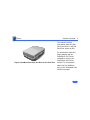
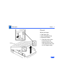
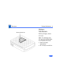
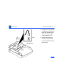
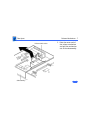
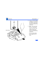
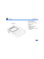
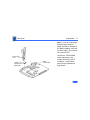
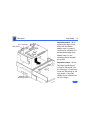
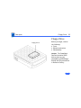
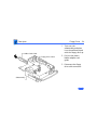
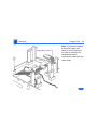
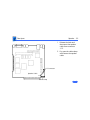
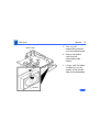
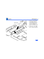
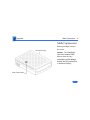
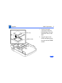
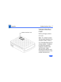
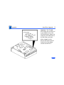
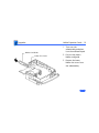
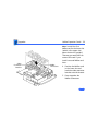
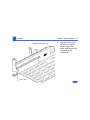
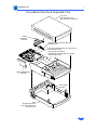
K Service Source
PowerBook Duo Dock
PowerBook Duo Dock, PowerBook Duo Dock II,
PowerBook Duo Dock Plus
K Service Source
Basics
PowerBook Duo Dock
Basics
System Overview - 1
System Overview
PowerBook Duo
System
Duo Dock/
Duo Dock II/
Duo Dock Plus
Duo Floppy
Adapter
Duo MiniDock
Duo
210/230
250/270c
280/280c
The PowerBook Duo system
includes the following
products:
• PowerBook 200 Series
computer (PowerBook
Duo 210/230/250/
270c/280/280c)
• PowerBook Duo Dock/Duo
Dock II/Duo Dock Plus
• PowerBook Duo MiniDock
• Floppy Adapter
Basics
System Overview - 2
This manual includes
information about the Duo
Dock, Duo Dock II, and Duo
Dock Plus, shown at left.
Figure: PowerBook Duo Dock, Duo Dock II, Duo Dock Plus
For information about the
floppy adapter and the
PowerBook 200 Series
computers, refer to the
PowerBook 200 Series
manual. For information
about the Duo MiniDock,
refer to the PowerBook Duo
MiniDock manual.
Basics
Repair Strategy - 3
Repair Strategy
Service the PowerDuo Dock, Duo Dock II, and Duo Dock Plus
through module exchange and parts replacement. Customers
can request on-site service from an Apple Authorized
Service Provider Plus (AASP+) Apple Assurance (US
only), or request a courier through the Apple Canada
Technical Answerline (Canada only). They can also choose
carry-in service from an AASP.
Ordering
Apple Service Providers planning to support the products
covered in this manual may purchase Service modules and
parts to develop servicing capability. To order parts, use the
AppleOrder (US only) or ARIS (Canada only) system and
refer to “Service Price Pages.”
Basics
Repair Strategy - 4
Large businesses, universities, and K-12 accounts must
provide a purchase order on all transactions, including
orders placed through the AppleOrder (US only) or ARIS
(Canada only) system.
USA Ordering
US Service Providers not enrolled in AppleOrder may fax
their orders to Service Provider Support (512-9088125) or mail them to
Apple Computer, Inc.
Service Provider Support
MS 212-SPS
Austin, TX 78714-9125
For US inquiries, please call Service Provider Support at
800-919-2775 and select option #1.
Basics
Repair Strategy - 5
Canadian Ordering
Canadian Service Providers not enrolled in ARIS may fax
their orders to Service Provider Support in Canada
(1-800-903-5284). For Canadian inquiries, please call
Service Provider Support at 905-513-5782 and select
option #3.
Basics
Warranty/AppleCare/ARIS - 6
Warranty/AppleCare/ARIS
US Only
The PowerBook Duo Dock, Duo Dock II, and Duo Dock Plus
are covered under the Apple One-Year Limited Warranty.
The AppleCare Service Plan is also available for these
products. Service Providers are reimbursed for warranty
and AppleCare repairs made to these products. For pricing
information, refer to “Service Price Pages.”
Canada Only
The PowerBook Duo Dock, Duo Dock II, and Duo Dock Plus
are covered under first-year AppleCare. The Extended
AppleCare Service Plan is also available for these products.
Service Providers are reimbursed for first-year warranty
and Extended AppleCare repairs made to these products. For
pricing information, refer to “Service Price Pages.”
Basics
Warranty/AppleCare/ARIS - 7
Duo Dock Configurations
The Duo Dock is available in standard and enhanced
configurations. The enhanced configuration includes:
• 230 MB hard drive
• Math coprocessor (68882 FPU chip at 25 MHz)
• 512K VRAM SIMM
• ADB Mouse II
Basics
Warranty/AppleCare/ARIS - 8
These items are options for the standard configuration of the
original Duo Dock. See the Specifications chapter for more
information.
The Duo Dock II is available in this standard configuration:
• Math coprocessor (68882 FPU chip) at 33MHz
• On-board Ethernet
• 1 MB VRAM SIMM
• ADB Mouse II
The Duo Dock Plus has the same features as the Duo Dock II,
but without the FPU and cache.
Basics
SCSI Devices - 9
SCSI Devices
SCSI ID Numbers
The PowerBook Duo Dock supports up to six SCSI devices. To
avoid conflicting SCSI ID numbers, assign external SCSI
devices numbers between 2 and 6. (The hard drive inside the
PowerBook Duo has SCSI ID number 0, and, if installed, the
hard drive inside the Duo Dock has ID number 1.)
Note: You must use an HDI-30 SCSI system cable to connect
external SCSI devices to the Duo Dock.
Caution: When making SCSI connections, always switch off
power to all devices in the chain.
Basics
SCSI Devices - 10
SCSI Termination
The PowerBook Duo Dock has a built-in SCSI terminator.
To terminate a SCSI chain connected to the dock, attach one
external terminator only to the last device in the chain, or
connect a SCSI device with built-in termination as the last
device in the chain.
Note: SCSI devices from other vendors may have built-in
terminators. If a SCSI device with a built-in terminator is
the last device in the chain, do not add an external
terminator to that device. If more than one SCSI device in the
chain has built-in terminators, you may need to remove the
extra internal terminators.
K Service Source
Specifications
PowerBook Duo Dock
Specifications
Introduction - 1
Introduction
You can also find specifications information for this product in the
Spec Database, which you can access in one of three ways:
— Launch it directly by double-clicking the Apple Spec Database
runtime alias at the top level of the Main Service Source CD.
— Select "Apple Spec Database" from the Service Source dropdown main menu.
— Click the Acrobat toolbar icon for the database, which is near
the right end of the toolbar with the letters "SP."
Specifications
Processor - 2
Processor
Coprocessor, Duo
Dock
Motorola 68882 FPU chip (optional for standard Duo Dock)
25 MHz
Coprocessor, Duo
Dock II
Motorola 68882 FPU chip and 32K RAM cache
33 MHz
Addressing
32-bit internal registers
32-bit address bus
32-bit data bus
Specifications
Memory - 3
Memory
ROM
Configuration ROM (differentiates between docking devices)
VRAM Duo Dock
512K of VRAM soldered on logic board
512K VRAM SIMM (optional for standard Duo Dock)
VRAM Duo Dock II/
Duo Dock Plus
I MB of VRAM soldered on logic board; no slot for additional VRAM
expansion
Specifications
Disk Storage - 4
Disk Storage
Floppy Drive
Internal 1.4 MB floppy drive
SWIM II MFM/GCR disk controller chip
Hard Drive, Duo
Dock/Duo Dock II
230 MB, 3.5 in., 1-in.-high SCSI hard drive (optional for Duo
Dock)
Internal 50-pin SCSI connector; external HDI-30 SCSI port
Specifications
I/O Interfaces - 5
I/O Interfaces
Docking Connector
SCSI
Apple Desktop Bus
Internal 152-pin processor-direct slot (PDS) connector to
PowerBook
32-bit expansion bus
HDI-30 SCSI port with 1.5 MB/sec. transfer rate
Supports up to six external SCSI devices (five if drive is
installed)
Includes built-in terminator
Connection to another computer requires HDI-30 SCSI system
cable
Apple Desktop Bus (ADB) port (recommend maximum of three
low-speed, synchronous ADB devices); mini DIN-4 connector
200 mA maximum current draw for all ADB devices
Specifications
I/O Interfaces - 6
Serial
Two RS-422 serial ports; mini DIN-8 connectors
NuBus
Two internal NuBus slots
Two 15 W cards, or one each at 25 W and 5 W
Ethernet
One internal Ethernet port (on Duo Dock II/Duo Dock Plus only)
Sound
Video
Monaural sound-in port (requires 20 dB attenuation cables and
adapters to accommodate audio equipment with line level outputs)
Monaural sound output jack for external audio amplifier
DB-15 connector supports Macintosh and some VGA monitors
(requires 15-pin-to-VGA adapter)
Specifications
Modem
I/O Interfaces - 7
Pass-through telephone jack for optional internal (PowerBook)
modem
RJ-11 domestic; mini DIN-8 international
Specifications
I/O Devices - 8
I/O Devices
Keyboard
Apple Keyboard II
Apple Extended Keyboard
Mouse
Apple Desktop Bus mouse
ADB Mouse II
Microphone
External electret, omnidirectional microphone
Output voltage of 4 mV, peak to peak
Speaker
16 Ω magnetic, moving coil speaker
Specifications
Video Support Duo
Dock
Video Support Duo
Dock II/Duo Dock
Plus
I/O Devices - 9
512K of built-in video plus a 512K VRAM SIMM
Supports all Macintosh monitors up to 16-in. color
Supports VGA monitors (requires NuBus card)
1 MB of VRAM supports up to 32,000 colors
1 MB of on-board VRAM
Supports most Macintosh monitors (including Apple Multiple
Scan monitors) up to 21-in. color
Supports some VGA monitors
Includes Sync On Green feature
Specifications
Electrical - 10
Electrical
Power Supply Duo
Dock
Power Supply Duo
Dock II/Duo Dock
Plus
Universal AC power supply, 85–270 VAC
Provides 75 W continuous power, 85 W surge power
47–63 Hz, single phase input line frequency
Charges PowerBook Duo batteries and powers Duo Dock
Universal AC power supply, 90–270 VAC
Provides 75 W continuous power, 85 W surge power
47–63 Hz, single phase input line frequency
Charges PowerBook Duo batteries and powers Duo Dock I or II
Specifications
Physical - 11
Physical
Dimensions Duo
Dock
Height: 4.75 in. (121 mm)
Width: 12.25 in. (311 mm)
Depth: 16.25 in. (413 mm)
Dimensions Duo
Dock II/Duo Dock
Plus
Height: 6.22 in. (158 mm)
Width: 12.75 in. (323.8 mm)
Depth: 16.37 in. (415.6 mm)
Weight Duo Dock
13.1 lb. (5.95 kg) without hard drive; frame supports up to 60
lb.
Weight Duo Dock II/
Duo Dock Plus
15 lb. without hard drive; frame supports up to 85 lb.
Specifications
Environmental - 12
Environmental
Operating
Temperature Duo
Dock
Operating
Temperature Duo
Dock II/Duo Dock
Plus
Storage
Temperature
Relative Humidity
50–104° F (10–40° C)
50–95° F (10–35° C)
-40 to 116° F (-40 to 47° C)
20–95% noncondensing
Specifications
Altitude
Environmental - 13
0–15,000 ft. (0–4722 m)
Specifications
Other - 14
Other
Modem
Docking Motor
Telephone line interface (DAA) circuitry (domestic)
Support for external telephone line interface (DAA) circuitry
(international)
RJ-11 connector (domestic); mini DIN-8 connector
(international)
Motorized injection/ejection mechanism draws the PowerBook
Duo system into the Duo Dock and ejects the system from the
Duo Dock
DC motor operates at 5 rpm and provides 16–30 lb. of pull-in
force
Specifications
Security
Other - 15
Key locking device at left front of unit locks PowerBook Duo
computer into the Duo Dock
Each lock is unique (no master key is available); 125 key
combinations
Key codes will be released to locksmiths
Hook at rear of monitor stand can be used with Kensington
mechanism to lock Duo Dock to the desktop
K Service Source
Troubleshooting
PowerBook Duo Dock
Troubleshooting
General - 1
General
The Symptom Charts included in this chapter will help you
diagnose specific symptoms related to your product. Because cures
are listed on the charts in the order of most likely solution, try
the first cure first. Verify whether or not the product continues to
exhibit the symptom. If the symptom persists, try the next cure.
(Note: If you have replaced a module, reinstall the original module
before you proceed to the next cure.)
If you are not sure what the problem is, or if the Symptom Charts
do not resolve the problem, refer to the Flowchart for the product
family.
For additional assistance, contact Apple Technical Support.
Troubleshooting
Hard Drives May Not Spin Up - 2
Hard Drives May Not Spin Up
When inserted into a Duo Dock or Duo Dock II+, your PowerBook
200 Series computer may not start from its internal hard drive.
The conditions that can cause the problem include:
• The PowerBook 200 Series (Duo) computer and Duo Dock hard
drives have been formatted with different versions of HD SC
Setup.
• Enough VRAM is installed to allow the option of thousands of
colors when the PowerBook 200 Series computer is inside the
Dock (unless thousands of colors are selected, the problem does
not occur).
• 32-bit addressing is on.
It can also occur with an external hard drive connected to the
Dock, or if a third party drive is installed inside the Duo Dock or
Duo Dock II+. In this case, reformatting both the PowerBook 200
Troubleshooting
Hard Drives May Not Spin Up - 3
Series computer and the Dock drives with the appropriate
formatter is required. Because Apple HD SC Setup does not
recognize third party drives, you need to use a third party
formatter.
To correct the problem, remove one of these conditions:
• Use HD SC Setup 7.2.2 or later to update the drivers on both
hard drives. This is available from authorized dealers or online services.
• Reformat the Powerbook 200 Series computer’s hard drive
with Apple HD SC Setup 7.1, or reformat both the Duo’s
internal hard drive and the Dock’s hard drive with the same
version of HD SC Setup.
• Turn off 32-bit addressing.
• When starting up from the Dock, set the colors to 256 instead
of thousands.
Source: Info Alley, June 1995
Troubleshooting
Symptom Charts/Startup - 4
Symptom Charts
Startup
RAM failure occurs
(eight-tone error
chord sequence
sounds after startup
chord)
1
2
Eject PowerBook Duo. Reboot and troubleshoot computer only.
Replace Duo Dock logic board. Retain VRAM SIMM, math
coprocessor, and SCSI terminator.
Troubleshooting
Hardware failure
occurs (four-tone
error chord sequence
sounds after startup
chord)
Symptom Charts/Startup - 5
1
2
3
4
Eject PowerBook Duo. Reboot and troubleshoot computer only.
Disconnect hard drive data cable, install standard Apple SCSI
terminator, and reboot system. If startup sequence is
normal, reseat cable, remove terminator, and retest. If
failure recurs, replace hard drive.
Disconnect floppy drive cable and reboot system. If startup
sequence is normal, reseat cable and retest. If hardware
failure recurs, replace floppy drive.
Replace Duo Dock logic board. Retain VRAM SIMM, math
coprocessor, and SCSI terminator.
Troubleshooting
Symptom Charts/Power - 6
Power
System doesn’t
respond
1
2
3
4
Eject PowerBook Duo. Reboot and troubleshoot computer only.
Check all Duo Dock logic board cable connections.
Replace Duo Dock power supply.
Replace Duo Dock logic board. Retain VRAM SIMM, math
coprocessor, and SCSI terminator.
System
intermittently
crashes or locks up
1
2
3
4
Make sure system software is 7.1 or higher.
Make sure software is known-good.
Eject PowerBook Duo. Reboot and troubleshoot computer only.
Replace Duo Dock logic board. Retain VRAM SIMM, math
coprocessor, and SCSI terminator.
Replace Duo Dock power supply.
5
Troubleshooting
System doesn’t power
up, power supply
makes ticking sound,
and display has no
raster
Symptom Charts/Power - 7
1
2
Measure to see if voltages for pins 5 and 7 on the power
supply-to-logic board cable fall between the following
ranges:
• Pin 5 (yellow wire) 5V + or - .5V
• Pin 7 (blue wire) 20V + or - .5V
If voltages don’t fall within the above ranges, replace Duo
Dock power supply.
Troubleshooting
Symptom Charts/Video - 8
Video
No external display,
but computer
appears to operate
correctly
1
2
3
4
5
6
7
Adjust screen contrast.
Reseat video cable.
Replace video cable.
Replace video interface card (if installed).
Replace VRAM SIMM (if installed).
Try known-good external display. If now OK, replace and
troubleshoot original display.
Replace Duo Dock logic board. Retain VRAM SIMM, math
coprocessor, and SCSI terminator.
Troubleshooting
Raster or video
display problems at
external monitor
Symptom Charts/Video - 9
1
2
3
4
5
6
7
Reseat video cable.
Replace video cable.
Replace video interface card (if installed).
Replace VRAM SIMM (if installed).
Try known-good external display. If now OK, replace and
troubleshoot original display.
Eject PowerBook Duo. Reboot and troubleshoot computer only.
Replace Duo Dock logic board. Retain VRAM SIMM, math
coprocessor, and SCSI terminator.
Troubleshooting
Symptom Charts/Floppy Drive - 10
Floppy Drive
Audio and video
present, but internal
floppy drive does not
operate
1
2
3
4
5
Try known-good floppy disk.
Check floppy drive cable connection.
Replace floppy drive cable.
Replace floppy drive.
Replace Duo Dock logic board. Retain VRAM SIMM, math
coprocessor, and SCSI terminator.
Disk ejects while
booting; display
shows Mac icon with
blinking X
1
2
3
4
5
6
Try known-good system disk.
Verify that mouse button is not stuck.
Check floppy drive cable connection.
Replace floppy drive cable.
Replace floppy drive.
Replace Duo Dock logic board. Retain VRAM SIMM, math
coprocessor, and SCSI terminator.
Troubleshooting
Disk does not eject
Symptom Charts/Floppy Drive - 11
1
2
3
4
5
6
Disk initialization
fails
1
2
3
4
5
Switch off system. To eject disk, hold mouse button down
while you switch system on.
Insert straightened paper clip into hole next to drive opening
and eject disk.
Check floppy drive cable connection.
Replace floppy drive cable.
Replace floppy drive.
Replace Duo Dock logic board. Retain VRAM SIMM, math
coprocessor, and SCSI terminator.
Verify that you are using correct media.
Try known-good floppy disk.
Check floppy drive cable connection.
Replace floppy drive cable.
Replace floppy drive.
Troubleshooting
Read/write/copy
error
Symptom Charts/Floppy Drive - 12
1
2
3
4
5
Verify that you are using correct media.
Try known-good floppy disk.
Check floppy drive cable connection.
Replace floppy drive cable.
Replace floppy drive.
Troubleshooting
Symptom Charts/Hard Drive - 13
Hard Drive
Internal PowerBook
hard drive does not
operate
Eject PowerBook Duo. Reboot and troubleshoot computer only.
Internal Duo Dock
hard drive does not
operate
1
2
3
4
5
6
Check internal hard drive data cable connection.
Replace internal hard drive data cable.
Run Macintosh Hard Disk Test.
Use HD SC Setup to reinitialize drive.
Replace internal hard drive.
Replace Duo Dock logic board. Retain VRAM SIMM, math
coprocessor, and SCSI terminator.
Troubleshooting
Symptom Charts/Hard Drive - 14
Internal hard drive
works, but external
SCSI device does not
1
2
3
4
Make sure external devices have unique switch settings
between 2 and 6.
Make sure SCSI chain is terminated at last device only.
Replace external SCSI terminator.
Troubleshoot external SCSI device.
Drive does not appear
on desktop
1
2
3
Restart system.
Verify that SCSI devices have unique addresses.
Use HD SC Setup to initialize drive.
Troubleshooting
Symptom Charts/Peripherals - 15
Peripherals
Cursor does not
move, or moves
erratically
1
2
3
4
5
6
Cursor moves, but
clicking mouse
button has no effect
1
2
Simultaneously press <Command> <Control> <Power On> keys
to reset computer.
Check ADB connections.
Inspect and clean mouse, if necessary.
If mouse was connected to keyboard, try in ADB port. If OK,
replace keyboard.
Replace mouse.
Replace Duo Dock logic board. Retain VRAM SIMM, math
coprocessor, and SCSI terminator.
Replace mouse.
Replace Duo Dock logic board. Retain VRAM SIMM, math
coprocessor, and SCSI terminator.
Troubleshooting
Symptom Charts/Peripherals - 16
No response to any
key on keyboard
1
2
3
4
5
Press <Power On> key or power button.
Check keyboard cable connection.
Replace keyboard cable.
Replace keyboard.
Replace Duo Dock logic board. Retain VRAM SIMM, math
coprocessor, and SCSI terminator.
Cannot double-click
to open application,
disk, or server
1
2
3
Remove any multiple system files.
Inspect and clean mouse, if necessary.
Clear parameter RAM and reset mouse controls. To clear
PRAM, start system, listen for boot tone, and immediately
depress <Option> <Command> <P> and <R> keys.
If mouse was connected to keyboard, try in ADB port. If OK,
replace keyboard.
Replace mouse.
Replace Duo Dock logic board. Retain VRAM SIMM, math
coprocessor, and SCSI terminator.
4
5
6
Troubleshooting
After you connect
external SCSI device,
computer doesn’t boot
Symptom Charts/Peripherals - 17
1
2
3
4
5
6
7
Known-good
ImageWriter,
ImageWriter II, or
LQ does not print
1
2
3
4
5
6
Switch on external SCSI device before starting computer.
Check cable connections.
Verify that standard Apple terminator terminates SCSI chain.
Verify that SCSI select switch setting on external device is
unique.
Verify operation of internal hard drive.
Try known-good external SCSI device.
Replace Duo Dock logic board. Retain VRAM SIMM, math
coprocessor, and SCSI terminator.
Verify that System is 7.1 or later.
Verify that Chooser and Control Panel settings are correct.
Check cables.
Replace printer interface cable.
Try known-good printer.
Replace Duo Dock logic board. Retain VRAM SIMM, math
coprocessor, and SCSI terminator.
Troubleshooting
Known-good
LaserWriter does not
print
Symptom Charts/Peripherals - 18
1
2
3
4
5
6
Device connected to
external modem port
doesn’t work
1
2
3
4
5
6
Verify that System is 7.1 or later.
Verify that Chooser and Control Panel settings are correct.
Check cables.
Replace printer interface cable.
Try known-good printer. If printer works, troubleshoot
network. Refer to Networks manual.
Replace Duo Dock logic board. Retain VRAM SIMM, math
coprocessor, and SCSI terminator.
Verify that External Modem is selected in PowerBook Control
Panel.
Verify that System is 7.1 or later.
Check cables.
Test device with known-good computer.
Eject PowerBook and test device at PowerBook external
modem/printer port.
Replace Duo Dock logic board. Retain VRAM SIMM, math
coprocessor, and SCSI terminator.
Troubleshooting
I/O devices are
unrecognized or
garbage is
transmitted or
received
Symptom Charts/Peripherals - 19
1
2
3
4
5
6
Verify that System is 7.1 or later.
Check cables.
Verify that SCSI devices are terminated properly.
Verify that SCSI select switch setting on external device is
unique between 2 and 6.
Test device with known-good computer.
Replace Duo Dock logic board. Retain VRAM SIMM, math
coprocessor, and SCSI terminator.
Troubleshooting
Symptom Charts/Internal Modem - 20
Internal Modem
Internal modem
options do not appear
in CDEV
1
2
3
4
5
Verify that System is 7.1 or later.
Remove and reseat modem interface board.
Eject PowerBook and test internal modem.
Replace modem interface board.
Replace Duo Dock logic board. Retain VRAM SIMM, math
coprocessor, and SCSI terminator.
Troubleshooting
Modem does not
respond properly to
AT command set
instructions
Symptom Charts/Internal Modem - 21
1
2
3
4
5
6
7
Verify that baud rate and data format settings of
communications application are compatible with internal
modem and remote modem.
Check phone cord connection and operation.
Verify that System is 7.1 or later.
Remove and reseat modem interface board.
Eject PowerBook and test internal modem.
Replace modem interface board.
Replace Duo Dock logic board. Retain VRAM SIMM, math
coprocessor, and SCSI terminator.
Troubleshooting
Symptom Charts/Internal Modem - 22
Strange mix of
characters appears
on screen
1
Modem interferes
with system sound
1
2
3
4
2
3
4
5
6
7
Verify that baud rate and data format settings of
communications application are compatible with internal
modem and remote modem.
Check phone cord connection and operation.
Verify that System is 7.1 or later.
Remove and reseat modem interface board.
Eject PowerBook and test internal modem.
Replace modem interface board.
Replace Duo Dock logic board. Retain VRAM SIMM, math
coprocessor, and SCSI terminator.
Remove and reseat modem interface board.
Eject PowerBook and test internal modem.
Replace modem interface board.
Replace Duo Dock logic board. Retain VRAM SIMM, math
coprocessor, and SCSI terminator.
Troubleshooting
Symptom Charts/Internal Modem - 23
Modem does not
respond to incoming
call
1
Modem has no sound
output
1
2
3
4
Verify that Control Panel volume setting is 1 or higher.
Eject PowerBook and test internal modem.
Replace modem interface board.
Replace Duo Dock logic board. Retain VRAM SIMM, math
coprocessor, and SCSI terminator.
Modem connects but
does not communicate
with remote modem
1
Verify that remote modem needs error correction (error
correction is internal modem default).
Type AT &Q0 to disable error correction.
2
3
4
5
2
If computer is in sleep mode, verify that “Answer calls” is
selected in Remote Access Setup control panel.
Check phone cord connection and operation.
Eject PowerBook and test internal modem.
Replace modem interface board.
Replace Duo Dock logic board. Retain VRAM SIMM, math
coprocessor, and SCSI terminator.
Troubleshooting
Symptom Charts/Miscellaneous - 24
Miscellaneous
Can’t insert
computer into dock
1
2
3
4
Unlock dock and insert computer.
Open I/O door on computer and insert computer.
Replace ejector assembly.
Replace Duo Dock logic board. Retain VRAM SIMM, math
coprocessor, and SCSI terminator.
Can’t eject computer
from dock
1
2
Unlock dock and press eject button again.
If no power to dock, insert dock’s key or small screwdriver
into square hole on side of dock and press to manually eject
computer.
Replace ejector assembly.
Replace Duo Dock logic board. Retain VRAM SIMM, math
coprocessor, and SCSI terminator.
3
4
Troubleshooting
Symptom Charts/Miscellaneous - 25
No sound from
speaker
1
2
3
Verify that volume setting in Control Panel is 1 or above.
Check speaker-to-logic board cable connection.
Replace Duo Dock logic board. Retain VRAM SIMM, math
coprocessor, and SCSI terminator.
Ejects computer
when you attempt to
start up from
keyboard
Shut down PowerBook and insert again.
K Service Source
Take Apart
PowerBook Duo Dock
Take Apart
Cover - 1
Cover
Before you begin,
• Shut down unit
• Eject PowerBook Duo
• Disconnect cables
1
Cover
Pinch the cover at the
horizontal grooves
inside the front of the
cover and raise the cover
to a 45-degree angle.
Take Apart
Cover - 2
2
Cover
Base
Lift the cover straight
up and remove it from
the base.
Take Apart
Cover - 3
Replacement Note:
When replacing the
cover, first place the
notches at the back
corners of the cover
into notches at the raised
corners of the base.
Take Apart
Release Mechanism
Release Mechanism - 4
Release
Mechanism
Before you begin, remove
the cover.
Note: The following tools
are required to disassemble
the PowerBook Duo Dock:
• Small flat-blade
screwdriver
• #2 crosstip screwdriver
Take Apart
Release Mechanism - 5
Caution: The PowerBook
Duo Dock contains CMOS
devices that are very
susceptible to ESD damage.
Review the ESD precautions
in Bulletins/Safety.
Take Apart
Release Mechanism - 6
1
Latch
J18 Connector
2
Using a small, flat-blade
screwdriver, release the
latch and disconnect the
two-wire motor cable
from connector J18.
Remove the four long
screws that secure the
release mechanism to the
logic board.
Take Apart
Release Mechanism - 7
Release Mechanism
Subassembly
3
Raise the motor end of
the release mechanism
and pull the mechanism
out of the subassembly.
Take Apart
Subassembly - 8
Subassembly
Latch
J11 Connector
Subassembly
Before you begin, remove
the following:
• Cover
• Release mechanism
Caution: The PowerBook
Duo Dock contains CMOS
devices that are very
susceptible to ESD damage.
Review the ESD precautions
in Bulletins/Safety.
1
Release the latch and
disconnect the power
supply cable from
connector J11.
Take Apart
Subassembly - 9
2
3
Subassembly
Using a small flat-blade
screwdriver, loosen the
two captive screws that
secure the subassembly
to the base.
Note: If you can’t pull
back the subassembly,
further loosen the two
captive screws that
secure the subassembly
to the base.
Pull the subassembly
back slightly until it
stops.
Base
Take Apart
Subassembly - 10
Subassembly
4
5
Base
Clear room on the
workbench pad beside
the base.
Lift the subassembly
straight up and remove
it from the base. Place
the subassembly beside
the base.
Take Apart
Subassembly - 11
Note: If you are
replacing a damaged
subassembly, first
remove the logic board,
floppy drive, hard drive
(if installed), ejector,
and speaker from the
subassembly. Refer to
the take-apart
procedures that follow.
Take Apart
Logic Board - 12
Logic Board
Logic Board
Before you begin, remove
the following:
• Cover
• Release mechanism
• Subassembly
• Modem interface card (if
installed)
Take Apart
Logic Board - 13
Caution: The PowerBook
Duo Dock contains CMOS
devices that are very
susceptible to ESD damage.
Review the ESD precautions
in Bulletins/Safety.
Take Apart
Logic Board - 14
1
J8
J11
J13
J17
J15
J14
If installed, disconnect
these cable connectors
from the logic board:
• Power supply cable
from J11
• Floppy drive cable
from J13
• Speaker cable from
J15
• Hard drive power
cable from J14
• Eject mechanism
cable from J17
• Hard drive data cable
from J8
Take Apart
Logic Board - 15
Note: You must first
release latches on the
power supply, speaker,
and eject mechanism
cables to disconnect them
from the logic board
connectors.
Take Apart
Logic Board - 16
2
Logic Board
3
PDS Connector
Subassembly
Remove the two
remaining logic board
mounting screws.
Raise the rear of the
logic board and pull it
out until the PDS
connector clears the
subassembly. Carefully
lift the logic board with
connected NuBus adapter
straight out of the
subassembly.
Take Apart
Logic Board - 17
Extraction
Tool
Math
Coprocessor
(Optional)
SCSI
Terminator
Note: If you are returning a
defective logic board to
Apple, be sure to disconnect
the NuBus adapter card (see
the next topic). Also remove
the internal SCSI
terminator, VRAM SIMM,
math coprocessor, and
modem interface card (if
installed). Install these
parts on the replacement
logic board.
Take Apart
Logic Board - 18
Note: To remove the
optional math coprocessor
from the original Duo Dock,
use the VGC IC extraction
tool (P/N 076-0264).
Insert the tongs of the
extraction tool into the
slotted corners of the chip,
and gently squeeze the
handle.
Take Apart
J12 Connector
EMI Shield
Adapter Card
Mounting Channel
Logic Board - 19
Replacement Note: When
replacing the logic board,
make sure the NuBus
adapter card is properly
connected to connector J12
and the bottom edge of the
adapter card is in the
mounting channel beneath
the chassis.
Replacement Note: All Duo
Dock logic boards should
include an EMI shield over
the video port. If necessary,
install the EMI shield on the
logic board. Extra EMI
shields can be ordered from
the Price Pages.
Take Apart
NuBus Adapter Card - 20
NuBus Adapter
Card
Before you begin, remove
the following:
• Cover
• Release mechanism
• Subassembly
• Modem interface card (if
installed)
• Logic board
NuBus Adapter Card
Take Apart
NuBus Adapter Card - 21
Caution: The PowerBook
Duo Dock contains CMOS
devices that are very
susceptible to ESD damage.
Review the ESD precautions
in Bulletins/Safety.
Take Apart
NuBus Adapter Card - 22
Gently rock the NuBus
adapter card from side to
side and disconnect it from
logic board connector J12.
J12 Connector
NuBus Adapter Card
Take Apart
Floppy Drive - 23
Floppy Drive
Floppy Drive
Before you begin, remove
the following:
• Cover
• Release mechanism
• Subassembly
Caution: The PowerBook
Duo Dock contains CMOS
devices that are very
susceptible to ESD damage.
Review the ESD precautions
in Bulletins/Safety.
Take Apart
Floppy Drive - 24
1
NuBus Card Guide
Floppy Drive Cable
2
3
Subassembly
Turn over the
subassembly and place
it on the workbench pad
with the floppy drive up.
Pull out the plastic
NuBus adapter card
guide.
Disconnect the floppy
drive cable connector.
Take Apart
Floppy Drive - 25
4
Floppy Drive
Floppy Disk Slot
5
Pull out the two rear
mounting latches and
slightly lift the rear of
the floppy drive.
Pull out the two front
latches and remove the
floppy drive from the
subassembly.
Replacement Note:
When replacing the
floppy drive in the
subassembly mount,
first lower the inject/
eject mechanism into the
floppy disk slot and then
push the drive down
until it latches.
Take Apart
Floppy Drive - 26
Floppy Drive Cable
Clamp
Note: If you need to replace
a defective floppy drive
cable, be sure to note how
the cable is routed in the
subassembly before
removing the cable from the
cable clamp.
Take Apart
Ejector - 27
Ejector
Ejector
Before you begin, remove
the following:
• Cover
• Release mechanism
• Subassembly
• Floppy drive
Caution: The PowerBook
Duo Dock contains CMOS
devices that are very
susceptible to ESD damage.
Review the ESD precautions
in Bulletins/Safety.
Take Apart
Ejector - 28
1
2
J17 Connector
Ejector Cable
Cable Clamp
Release the latch and
disconnect the ejector
cable from connector
J17.
Pry open the cable clamp
and remove the ejector
cable.
Take Apart
Ejector - 29
3
Ferrite Bead
Push down on the flat
surface of the ferrite
bead and pull open the
two halves of the bead.
Remove the ferrite bead
from the ejector cable.
Take Apart
Ejector - 30
4
5
Ejector
Cable
Mounting
Bracket
Subassembly
Ejector
Turn over the
subassembly and place
it on the workbench pad.
Unlace the ejector cable
from the subassembly.
Remove the ejector
from the mounting
bracket on the outside
edge of the subassembly.
Take Apart
Speaker - 31
Speaker
Before you begin, remove
the following:
• Cover
• Release mechanism
• Subassembly
• Floppy drive
Speaker
Caution: The PowerBook
Duo Dock contains CMOS
devices that are very
susceptible to ESD damage.
Review the ESD precautions
in Bulletins/Safety.
Take Apart
Speaker - 32
1
2
J15 Connector
Speaker Cable
Cable Clamp
Release the latch and
disconnect the speaker
cable from connector
J15.
Pry open the cable clamp
and remove the speaker
cable.
Take Apart
Speaker - 33
Cable Clamp
3
4
5
Speaker
Turn over the
subassembly and place
it on the workbench pad.
Remove the speaker
cable from the
subassembly cable
clamps.
Using a small flat-blade
screwdriver, pry the
speaker off the outside
edge of the subassembly.
Take Apart
Power Supply - 34
Power Supply
Power Supply
Before you begin, remove
the following:
• Cover
• Release mechanism
• Subassembly
Caution: The PowerBook
Duo Dock contains CMOS
devices that are very
susceptible to ESD damage.
Review the ESD precautions
in Bulletins/Safety.
Take Apart
Power Supply - 35
1
2
Power Supply
Base
Depress the two plastic
latches and push in the
power supply at the
receptacle.
Remove the power
supply from the base.
Take Apart
Power Supply - 36
Power Supply Cutouts
Mounting Tabs
Rear
Panel
Replacement Note: When
replacing the power supply,
you must first hook the
cutouts in the bottom of the
power supply over the
three mounting tabs in the
base. Then firmly push the
power supply toward the
rear panel until the power
supply latches into place.
Take Apart
Lock Plug Assembly - 37
Lock Plug
Locking Clip
Lock Plug
Assembly
Before you begin, remove
the following:
• Cover
• Release mechanism
• Subassembly
Caution: The PowerBook
Duo Dock contains CMOS
devices that are very
susceptible to ESD damage.
Review the ESD precautions
in Bulletins/Safety.
Lock Plug Assembly
1
Pull the locking clip off
the end of the lock plug.
Take Apart
Lock Plug Assembly - 38
2
Push the lock plug out of
the base.
Take Apart
Base - 39
Base
Base
To access the base, remove
the following:
• Cover
• Release mechanism
• Subassembly
• Power supply
K Service Source
Upgrades
PowerBook Duo Dock
Upgrades
VRAM Upgrade - 1
VRAM Upgrade
VRAM SIMM
Before you begin, remove
the cover.
Caution: The PowerBook
Duo Dock contains CMOS
devices that are very
susceptible to ESD damage.
Review the ESD precautions
in Bulletins/Safety.
Duo Dock (only)
Upgrades
VRAM Upgrade - 2
Note: The PowerBook Duo
Dock has 512K of video RAM
soldered on the logic board.
You can increase the amount
of VRAM to 1 MB by
installing a 512K VRAM
SIMM in the SIMM slot
(connector J9). Use only
100 ns or faster VRAM
SIMMs.
Note: You cannot increase
the amount of video RAM on
the Duo Dock II, which
comes with 1 MB VRAM.
Upgrades
VRAM Upgrade - 3
1
VRAM SIMM
2
J9 SIMM Slot
Grasp the VRAM SIMM
by its edges with the
contacts pointing down.
Insert the SIMM at an
angle into SIMM slot J9.
Push back on the SIMM
until it snaps into place.
Upgrades
Math Coprocessor - 4
Math Coprocessor
Duo Dock (only)
Math Coprocessor
Before you begin, remove
the cover.
Caution: The PowerBook
Duo Dock contains CMOS
devices that are very
susceptible to ESD damage.
Review the ESD precautions
in Bulletins/Safety.
Upgrades
Math Coprocessor - 5
Note: You can add a Motorola
68882 math coprocessor to
the logic board of the
original Duo Dock, thereby
increasing the overall
performance of the
Macintosh Duo System.
Note: The Duo Dock II
includes a math coprocessor
and therefore does not need
this upgrade.
Upgrades
Math Coprocessor - 6
1
FPU Chip
2
68882 Socket
Position the math
coprocessor with the
beveled edge of the chip
toward the front of the
dock.
Align the pins in the
socket and gently press
the chip into the 68882
socket.
Upgrades
Modem Interface Card - 7
Modem Interface Card
Modem Interface
Card
Before you begin, remove
the cover.
Note: The modem interface
card provides telephone line
interface (DAA) circuitry
for a PowerBook Duo with an
internal modem. To address
the differences between
telephone interfaces and
specifications, Apple
provides both domestic and
international versions of the
modem interface card.
Upgrades
Modem Interface Card - 8
Caution: The Duo Dock
contains CMOS devices that
are very susceptible to ESD
damage. Review the ESD
precautions in Bulletins/
Safety.
Upgrades
Modem Interface Card - 9
1
2
Subassembly
Modem Interface
Card
J10 DAA
Connector
Jumper
3
Remove the modem port
cover from the
subassembly.
Insert the modem
interface card telephone
jack into the modem port
and position the modem
interface card on the
chassis. Using a small
flat-blade screwdriver,
press the modem
connector onto DAA
connector J10.
Install the two modem
card mounting screws.
Upgrades
Modem Interface Card - 10
Important: In Japan
only, install a jumper on
modem interface
connector J3. A jumper
is included with every
modem interface card.
Upgrades
Hard Drive Upgrade - 11
Hard Drive
Upgrade
Before you begin, remove
the following:
• Cover
• Release mechanism
• Subassembly
• Floppy drive
Hard Drive
Upgrades
Hard Drive Upgrade - 12
Caution: The PowerBook
Duo Dock contains CMOS
devices that are very
susceptible to ESD damage.
Review the ESD precautions
in Bulletins/Safety.
Note: Any 3.5-inch, 1inch-high hard drive can be
installed in the hard drive
bay in the Duo Dock.
Upgrades
Hard Drive Upgrade - 13
SCSI Jumper
A0
A1
A2
Important: The 230 MB
drive ships with a SCSI ID of
0 (no jumpers are on the
SCSI select pins). When you
install the 230 MB drive in
the Duo Dock, you must
place a jumper on the
drive’s SCSI select pins at
location A0. The jumper
creates a SCSI ID of 1.
Upgrades
Hard Drive Upgrade - 14
Hard Drive
Access Hole
Cable Clamp
Cable
Clamp
1
2
3
Cable
Clamp
Data Cable
Cable Clamp
Turn over the
subassembly and place
it on the workbench pad.
Position the hard drive
in the subassembly as
shown.
Route the hard drive data
cable and the hard drive
power cable beneath the
floppy drive bay and
through the chassis
access hole. Hook the
cables beneath the cable
clamps as shown.
Upgrades
Hard Drive Upgrade - 15
4
Drive Mounting
Latches
Lower the hard drive and
push down on the drive
until it snaps beneath
the mounting latches.
Upgrades
Hard Drive Upgrade - 16
5
6
J8 Connector
J14 Connector
Remove the SCSI
terminator from
connector J8.
Connect the hard drive
data cable to connector
J8 and the hard drive
power cable to
connector J14.
Upgrades
NuBus Expansion Cards - 17
NuBus Expansion
Cards
Before you begin, remove
the following:
• Cover
• Release mechanism
• Subassembly
NuBus Expansion Card
Upgrades
NuBus Expansion Cards - 18
Caution: The PowerBook
Duo Dock contains CMOS
devices that are very
susceptible to ESD damage.
Review the ESD precautions
in Bulletins/Safety.
Note: Install this card only
on the original Duo Dock; it
is unnecessary on the Duo
Dock II, which already
supports Ethernet.
Upgrades
NuBus Expansion Cards - 19
1
NuBus Card Guide
Lower Slot Cover
2
3
Turn over the
subassembly and place
it on the workbench pad.
Pull out the plastic
NuBus card guide.
Remove the lower
NuBus slot cover from
the subassembly.
Upgrades
Video
Connector
Bracket
NuBus Expansion Cards - 20
NuBus
Connectors
Note: Install the first
NuBus card in the lower slot
(which is the upper slot
when the dock is upright).
That way you won’t have to
remove this card if you
install a second NuBus card
later.
4
5
Position the NuBus card
in the lower slot and
hook the video connector
bracket onto the chassis.
Press together the
NuBus connectors.
Upgrades
NuBus Expansion Cards - 21
NuBus Card Guide
Lower Slot
6
Align the lower slot in
the NuBus card guide
with the edge of the
NuBus card. Replace the
card guide on the
subassembly.
Upgrades
Duo Dock II Upgrade - 22
Cover
Logic
Board
Duo Dock II
Upgrade
Before you begin, remove
the following:
• Cover
• Release mechanism
• Subassembly
• Modem interface card (if
installed)
Upgrades
Duo Dock II Upgrade - 23
Caution: The Macintosh Duo
Dock contains CMOS devices
that are very susceptible to
ESD damage. Review the ESD
precautions in Bulletins/
Safety.
Note: Upgrade the Duo Dock
to a Duo Dock II by adding a
new logic board and cover.
These parts are available
individually, not as a kit.
Upgrades
Duo Dock II Upgrade - 24
1
Install the Duo Dock II
logic board and cover
(see “Logic Board” and
“Cover”).
K Service Source
Exploded View
PowerBook Duo Dock
Exploded View
1
PowerBook Duo Dock Exploded View
Top Cover
922-0519 (Duo Dock)
815-0459 (Duo Dock II/Plus)
Release
Mechanism
922-0336
Modem Interface Card 922-0095 (US)
922-0094 (Int'l)
Logic Board Assembly 661-1707 (Duo Dock II)
661-1657 (Duo Dock)
661-0975 (Duo Dock Plus)
Subassembly 076-0466 (Duo Dock II/Plus)
922-0106 (Duo Dock)
NuBus Adapter Board
922-0102
Power Supply
661-1660
Base
815-0458 (Duo Dock)
076-0465 (Duo Dock II/
Duo Dock Plus)