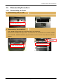
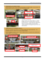
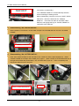
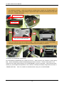
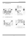
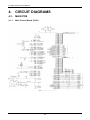
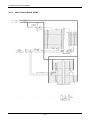
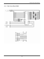
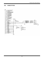
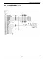
1
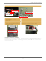
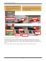
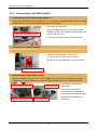
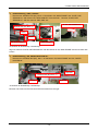
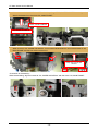
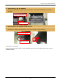
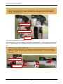
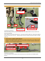
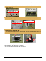
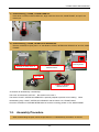
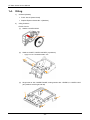
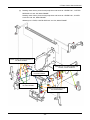
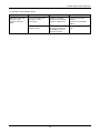
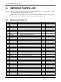
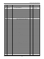
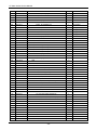
Service Manual
COMPACT LINE THERMAL PRINTER
CT-S851 Series
Revision 1.00 2010.2.25
CT-S851 Series Service Manual
REVISIONS
Rev No.
Date
1.00
2010/2/25
Page
Comment
Newly issued
CITIZEN is a registered trademark of CITIZEN HOLDINGS CO., LTD., Japan.
CITIZEN es una marca registrada de Citizen Holdings Co., Japón.
-1-
CT-S851 Series Service Manual
CONTENTS
INTRODUCTION .............................................................................................4
1.
2.
DISASSEMBLY AND REASSEMBLY.......................................................4
1-1.
Tools Used .........................................................................................................................4
1-2.
Disassembly Procedure .....................................................................................................5
1-2-1.
Disassembling the Printer....................................................................................5
1-2-2.
Disassembling “UNIT, MECHANISM” ................................................................14
1-3.
Assembly Procedure........................................................................................................23
1-4.
Oiling................................................................................................................................24
TROUBLESHOOTING ...........................................................................27
2-1.
Error Indication.................................................................................................................27
2-2.
Explanations of Error Conditions......................................................................................28
2-2-1.
Paper Near End .................................................................................................28
2-2-2.
Paper End..........................................................................................................28
2-2-3.
Front Cover Open ..............................................................................................28
2-2-4.
Paper Cover Open.............................................................................................28
2-2-5.
Cutter Error........................................................................................................28
2-2-6.
Black Mark Error ................................................................................................28
2-2-7.
Print Head Hot ...................................................................................................28
2-2-8.
Memory Error.....................................................................................................28
2-2-9.
Print Head Error.................................................................................................29
2-2-10. Motor Error ........................................................................................................29
2-2-11. Low Voltage Error ..............................................................................................29
2-2-12. High Voltage Error .............................................................................................29
2-2-13. Drawer Voltage Error .........................................................................................29
2-2-14. Macro Execution Wait ........................................................................................29
2-3.
Troubleshooting Procedure..............................................................................................30
2-4.
Troubleshooting Guide.....................................................................................................30
-2-
CT-S851 Series Service Manual
3.
SERVICE PARTS LIST ..........................................................................34
3-1.
Mechanical Parts List.......................................................................................................34
3-1-1.
3-2.
4.
Mechanical Exploded Diagrams ........................................................................40
Parts Layout.....................................................................................................................47
3-2-1.
SA, MAIN PCB ..................................................................................................47
3-2-2.
SA, DC PCB ......................................................................................................49
3-2-3.
SA, SERIAL I/F PCB..........................................................................................49
3-2-4.
SA, PARALLEL I/F PCB.....................................................................................50
3-2-5.
SA, USB I/F PCB ...............................................................................................50
3-2-6.
SA, USB HUB I/F PCB ......................................................................................51
3-2-7.
SA, POWERED USB I/F PCB ...........................................................................51
CIRCUIT DIAGRAMS.............................................................................52
4-1.
MAIN PCB .......................................................................................................................52
4-1-1.
Main Control Board (CPU1)...............................................................................52
4-1-2.
Main Control Board (CPU2/DAC) ......................................................................53
4-1-3.
Main Control Board (ROM) ................................................................................54
4-1-4.
Main Control Board (RAM) ................................................................................55
4-1-5.
Main Control Board (GATE_ARRAY) .................................................................56
4-1-6.
Main Control Board (HEAD, OP-PANEL)...........................................................57
4-1-7.
Main Control Board (PF MOTOR)......................................................................57
4-1-8.
Main Control Board (SENSOR) .........................................................................58
4-1-9.
Main Control Board (POWER/DRAWER/BUZZER)...........................................59
4-1-10. Main Control Board (IF PCB CON / OPTION IF) ...............................................60
4-1-11. Main Control Board (CUTTER) ..........................................................................61
4-2.
PE, PNE Sensor ..............................................................................................................62
4-3.
Operation Panel ...............................................................................................................62
4-4.
Serial I/F PCB ..................................................................................................................63
4-5.
Parallel I/F PCB ...............................................................................................................64
4-6.
USB I/F PCB ....................................................................................................................65
4-7.
USB HUB I/F PCB ...........................................................................................................66
4-8.
POWERED USB I/F PCB ................................................................................................67
-3-
CT-S851 Series Service Manual
INTRODUCTION
This manual describes the disassembly, reassembly, and maintenance procedures of CT-S851 Series.
1.
DISASSEMBLY AND REASSEMBLY
Note the following items when performing maintenance of the printer.
• Do not disassemble, reassemble, or adjust the printer unnecessarily when the printer operation is
satisfactory.
• Do not loosen the screws that fasten the components unless it is absolutely necessary.
• After finishing inspection, perform a check to ensure that there is no irregularity before turning on the
printer.
• Use caution not to leave any part or screw used for maintenance inside the printer.
• When handling the print head and electronic components, care must be taken to avoid static electricity.
• When disassembling or reassembling the printer, check the wires and cords for damage. Do not draw
any wire or cord by force.
• Lubricate the components as necessary when reassembling them.
1-1.
Tools Used
• Phillips screwdriver #0, #1, and #2
• Tweezers
• Long-nose pliers
• Brush
-4-
CT-S851 Series Service Manual
1-2.
Disassembly Procedure
1-2-1.
Disassembling the Printer
1.
Disassembling “UNIT, I/F PCB”
Remove two “SCREW, BHT (ST), M3.0 × 6” that fasten “FRAME, BOTTOM” and “UNIT, I/F PCB”.
SCREW, BHT (ST), M3.0 × 6
2.
Disassembling “SA, COVER-02”
Push “KNOB, COVER OPEN -02” upward and open “SA, COVER-02”.
Remove three “SCREW, BHT (PT), M3.0 × 10” and remove “SA, COVER-02” from “COVER, FRAME”.
Hold “HOLDER, DAMPER PAPER-02” by hand until two screws come into view, and remove the two
screws.
HOLDER, DAMPER
PAPER-02
SCREW, BHT (PT), M3.0 × 10
KNOB, COVER OPEN-02
-5-
CT-S851 Series Service Manual
Since “SA, COVER-02” is secured with hooks and the boss, it cannot be removed easily when it is fully
opened. To remove “SA, COVER-02”, slightly close it by hand, raise its front edge, and slide it
backward.
When mounting “SA, COVER-02”, align the boss with the hole at “COVER, FRAME” and slide “SA,
COVER-02” upward with hooks inserted into “COVER, FRAME”.
Boss
Hooks
NG
OK
<Precaution at disassembly / reassembly>
The hooks and the boss at “SA, COVER-02” are engaged on “FRAME, COVER”. Carefully disassemble or
reassemble the components so as not to damage them. Check the routing of “SA, HEAD CABLE-02”.
-6-
CT-S851 Series Service Manual
3.
Disassembling “SA, HEAD COVER”
Detach the lugs from the notches at the right and left sides of “COVER, FRAME”, and move down “SA,
HEAD COVER” and pull it out with care so as not to damage the lugs.
Bosses at right
and left sides
SA, HEAD COVER
Lugs at right
and left sides
<Precaution at reassembly>
Hooks
4.
Hang the hooks at “SA, HEAD COVER” on “COVER,
FRAME” and raise “SA, HEAD COVER” using these
hooks as fulcrums. Let the bosses at the right and left
sides of “SA, HEAD COVER” fit into the holes at
“COVER, FRAME”, and engage the lugs to secure “SA,
HEAD COVER”.
Disassembling “SA, THERMAL HEAD-02”
Move down “HOLDER, HEAT SINK-02” by pressing the edges at the right and left sides. “SA,
THERMAL HEAD-02” is detached from lugs at “COVER FRAME”.
Pull “SA, THERMAL HEAD-02” out from “SHAFT, HEAD ADJUST-2” along the U-slot, and disconnect
“HEAD CABLE” from two positions.
HOLDER, HEAT SINK-02
Lugs at “COVER, FRAME”
HEAD CABLE
SHAFT, HEAD ADJUST-2
BOSS
-7-
Heating section at “SA,
THERMAL HEAD-2”
U-slot
CT-S851 Series Service Manual
Align the bosses with
“SPRING, HEAD-02”.
<Precaution at reassembly>
“SA, THERMAL HEAD-02” is electrostatically sensitive.
Avoid contacting the heating section.
When reassembling, insert the U-slot into “SHAFT, HEAD
ADJUST-2”, and let the bosses fit into “SPRING,
HEAD-02”. Press the both sides at “HOLDER, HEAT
SINK-02” and engage the lugs at “COVER, FRAME” on
“HOLDER, HEAT SINK-02”.
5.
Disassembling “SA, PLATEN UNIT-02”
Raise “HANDLE, PLATEN-02” on both sides, and pull “SA, PLATEN UNIT-02” out from “SA, MAIN
FRAME”.
SA, PLATEN UNIT-02
HANDLE, PLATEN-02
6.
Disassembling “SA, CUTTER UNIT-02”
Push “PIN, FRONT COVER” at the right side of “SA, CASE-02” using a sharp-pointed tool. Raise
“FRONT COVER-02” and flip it down toward you to open it. When “LEVER, CUTTER RELEASE-02” at
the right and left sides are pushed down, “SA, CUTTER UNIT” pops out. Pull it out upwardly and
disconnect cables from the connector.
Connector
LEVER, CUTTER RELEASE-02
-8-
CT-S851 Series Service Manual
7.
Disassembling “SA, FRONT COVER-02”
Remove two “SCREW, BHT (ST), M3.0 × 6” that fasten “SA, FRONT COVER-02” and “SA, MAIN
FRAME” and disconnect “SA, OPEPANE CABLE F” from the connector.
Remove “HOLDER, FRONT COVER-02” from “SA, FRONT COVER-02”.
SCREW, BHT (ST), M3.0 × 6
SA, OPEPANE CABLE F
SA, FRONT COVER-02
HOLDER, FRONT COVER-02
Remove “HOLDER, FRONT COVER-02” while pulling its side edge outwardly.
8.
Disassembling “SA, CASE-02”
Remove two “SCREW, BHT (ST), M3.0 × 6” that fasten “SA, CASE-02” and “SA, MAIN FRAME”.
Raise the front edge of “SA, CASE-02” while slightly pressing “POWER SW” at the front.
SCREW, BHT (ST), M3.0 × 6
-9-
CT-S851 Series Service Manual
Close “SA, COVER FRAME” slightly, and raise “SA, CASE-02” while pulling the right and left edges of
“SA, CASE-02” outwardly. When “SA, CASE-02” is raised slightly, release “SA, COVER FRAME” and
raise “SA, CASE-02” further while pulling the right and left edges outwardly and keeping the lugs at the
rear clear of “FRAME, BOTTOM”.
SA, COVER FRAME
SA, CASE-02
Be sure to keep lugs at the right and left
sides clear of “FRAME BOTTOM”.
Raise “SA, CASE-02” along “SA, COVER FRAME”. When “SA, CASE-02” is raised to the position
indicated in the photo below, turn it counterclockwise and pull it upwardly to remove it.
<Precaution at disassembly / reassembly>
Do not assemble or disassemble “SA, CASE-02” by force. When removing “SA, CASE-02”, raise it little by
little. When reassembling, follow the disassembly procedure in reverse. Face the front panel of “SA,
CASE-02” to the right, pass it through “SA, COVER FRAME”, and turn it clockwise. When the front faces
toward you, pull the right and left panels of “SA, CASE-02” outwardly and keep the lugs at the rear clear of
“FRAME, BOTTOM”. Push “SA, CASE-02” downward while closing “SA, COVER FRAME”.
- 10 -
CT-S851 Series Service Manual
Remove “SA, OPEPANE CABLE-F” and “SA, CUTTER CABLE”.
J17: SA, CUTTER
SA, CUTTER CABLE
J3: SA, OPEPANE
SA, OPEPANE CABLE-F
9.
Disassembling “COVER,
ADAPTER”
Remove four “SCREW, BHT (ST), M3.0 ×
6” that fasten “COVER, ADAPTER” and
“FRAME, BOTTOM”.
Remove the AC adaptor cable from the power connector.
(Note that this connector is of the lock type.)
SCREW, BHT (ST), M3.0 × 6
<Precaution at disassembly / reassembly>
The power connector is a lock-type connector. Unlock the connector by pulling the outer slide at the end of
the connector to disconnect the cable. When fitting the connector, insert it until it clicks and ensure that it
cannot be removed easily.
- 11 -
CT-S851 Series Service Manual
10. Disassembling “FRAME, BOTTOM”
Remove four “SCREW, BHT (ST), M3.0 × 6”
that fasten “FRAME, BOTTOM” and “SA,
MAIN FRAME”.
Detach the lower lugs and raise “FRAME, BOTTOM”.
Slide “FRAME, BOTTOM” upward to detach upper lugs
from “SA, MAIN FRAME”.
Slide upward.
SCREW, BHT (ST), M3.0 × 6
Lugs
Lugs
Lugs
Four slots
DC connector
Slide
downward.
DK connector
External device
connector
<Precaution at disassembly / reassembly>
When dismounting or mounting “FRAME, BOTTOM”, be careful not to damage the DC connector, DK
connector, and external device connector. When mounting “FRAME, BOTTOM”, align the lugs with four
slots, at which “FRAME, BOTTOM” is to be secured, slide it downward to engage the lugs, and fasten it with
screws.
Be careful not to allow connectors to interfere with each other in order to prevent deformation.
- 12 -
CT-S851 Series Service Manual
.
11. Disassembling “UNIT, MAIN PCB”
Remove four “SCREW, BHT (ST), M3.0 × 6”
that fasten “UNIT, MAIN PCB” and “SA, MAIN
FRAME”.
Remove one “SCREW, BHT (ST), M3.0 × 6” that
fastens “COVER, CABLE PROTECT-02” at the right
side, and disconnect the connector of “COVER OPEN
SENSOR”.
SCREW, BHT (ST), M3.0 × 6
SCREW, BHT (ST), M3.0 × 6
COVER, CABLE PROTECT-02
Pass “COVER OPEN
SENSOR” through this hole.
J10: COVER OPEN SENSOR
Disconnect the connectors of “SA, HEAD
CABLE-02” and “SA, PNE SENSOR” at the
left side.
Disconnect the connector of “SA, POWER SW” at the
rear.
J2: SA, HEAD CABLE-02
J12: SA, POWER SW
J5: SA, PNE SENSOR
Disconnect the connectors of “SA, PE SENSOR” and “UNIT, MOTOR” at the front, and remove “UNIT, MAIN
PCB”.
J11: SA, PE SENSOR
J4: UNIT, MOTOR
<Precaution at reassembly>
Connectors are provided at the right, left, and front sides. Be careful not to pull these cables by force.
When reassembling, be careful not to miss or catch any part, such as “FRAME”. Before disassembling
record the cable routing. When reassembling, reconnect the cables correctly. Pass “CABLE” of “COVER
OPEN SENSOR” through the hole on “COVER, CABLE PROTECT-02” and secure it.
- 13 -
CT-S851 Series Service Manual
1-2-2.
1.
Disassembling “UNIT, MECHANISM”
Disassembling “SA, COVER OPEN SENOR - F”
Remove two “SCREW, No. 0 PHT (BT#3), M1.7 × 7” that fasten “SA, MAIN FRAME” and “SA, COVER
OPEN SENSOR” (2 pcs), as well as the tape that secures “CABLE”.
<Precaution at reassembly>
SCREW, No. 0 PHT (BT#3), M1.7 × 7
When reassembling, align the “SA, COVER OPEN
SENSOR” switch with the hole at “FRAME, MAIN”, and
secure it with one screw.
Do not forget to attach a tape to secure the cable.
2.
Disassembling “GEAR DAMPER”
Remove two “SCREW, BHT (ST), M2.0 × 4” that fasten “SA, MAIN FRAME” and “GEAR, DAMPER”.
<Precaution at disassembly / reassembly>
The unit can be mounted in either orientation.
This part is not compatible with the one for CT-S801.
SCREW, BHT (ST), M2.0 × 4
3.
Disassembling “GEAR REDUCTION”
Remove “SCREW, PHT (#2), M3.0 × 8” and “SCREW, PHT (ST), M3.0 × 6” that fasten “SA, MAIN
FRAME” and “COVER, GEAR-02”, and remove “GEAR REDUCTION” from “COVER, GEAR-02”.
SCREW, PHT (ST), M3.0 × 6
SCREW, PHT (#2), M3.0 × 8
COVER, GEAR-02
GEAR REDUCTION
- 14 -
<Precaution at disassembly /
reassembly>
If the screws are tightened
excessively when reassembling,
“COVER, GEAR” will be damaged.
Be careful not to tighten them
excessively.
CT-S851 Series Service Manual
4.
Disassembling “UNIT, PNE-02”
Remove two “SCREW, PHT (#2), M3.0 × 8” that fasten “SA, MAIN FRAME” and “PLATE, PNE
SENSOR-02”, and remove “SA, HEAD CABLE-F” from the hook. Remove “PLATE, PNE
SENSOR-02”, and then remove “UNIT, PNE -02”.
PLATE, PNE SENSOR-02
SCREW, PHT (#2), M3.0 × 8
BOSS
Hooks
SA, HEAD CABLE-F
UNIT, PNE-02
<Precaution at disassembly / reassembly>
Align two holes at “PLATE, PNE SENSOR-02” with the bosses at “SA, MAIN FRAME” and secure them with
screws.
5.
Disassembling “SA, PAPER HOLDER-02”
Remove four “SCREW, BHT (BT), M3.0 × 6” that fasten “SA, MAIN FRAME” and “SA, PAPER
HOLDER-02”.
Right side
SCREW, BHT (BT), M3.0 × 6
Left side
Right side
<Precaution at disassembly / reassembly>
Remove one screw from the left rear and three screws from the right.
- 15 -
CT-S851 Series Service Manual
Raise the rear of “SA, PAPER HOLDER-02” while pulling “GEAR, COVER DAMPER” outwardly, and
detach the bosses from the slot at “SA, MAIN FRAME”.
GEAR, COVER DAMPER
SA, PAPER HOLDER-02
When removing “SA, PAPER HOLDER-02”, pull it upward while keeping it clear of the bosses at “SA,
MAIN FRAME” and the bent section at the front.
Keep clear of these four
sections.
<Precaution at reassembly>
When reassembling, align the bosses at “SA, PAPER HOLDER-02” with the slot at “SA, MAIN FRAME”.
- 16 -
CT-S851 Series Service Manual
6.
Disassembling “SA, PE SENSOR”
Remove two “SCREW, PHT (BT), M2.0 × 6” that fasten “SA, PAPER HOLDER-02” and “SA, PE
SENSOR”.
SCREW, PHT (BT), M2.0 × 4
SA, PE SENSOR
7.
Disassembling “SA, FRAME COVER UNIT-02”
Remove “WASHER, PLATEN” that fastens the hinged section at “SA, FRAME MAIN” to “SA, FRAME,
COVER” and “GEAR, COVER DAMPER”, and remove “GEAR, COVER DAMPER”.
GEAR, COVER DAMPER
WASHER, PLATEN
<Precaution at reassembly>
When reassembling, align “GEAR, COVER DAMPER” with the shaft at “FRAME, MAIN” and the boss at
“FRAME, COVER”.
- 17 -
CT-S851 Series Service Manual
Remove “WASHER, PLATEN” from the “COVER, CABLE-02” side, and remove “SA, FRAME COVER
UNIT-02” from the hinged section at “SA, MAIN FRAME”. When removing “SA, FRAME COVER
UNIT-02”, make sure that “SA, FRAME COVER UNIT-02” is opened and that no load is applied to
“SPRING, COVEROPEN-02”.
WASHER, PLATEN
SPRING, COVEROPEN-02
With bend
<Precaution at disassembly / reassembly>
When reassembling, check the orientation of “SPRING, COVEROPEN-02”. Attach the bent side to the hook
at the “SA, MAIN FRAME” side, and attach the other side to the hook at the “SA, FRAME COVER UNIT-02”
side.
8.
Disassembling “COVER, CABLE-02”
Remove “SCREW, PHT (ST), M2.0 × 4” that fastens “SA, FRAME COVER UNIT-02” and “COVER,
CABLE-02”, and slide “COVER, CABLE-02” sideways to detach the hooks. Then pull out “COVER,
CABLE-02”.
SCREW, PHT (ST), M2.0 × 4
COVER CABLE-02
- 18 -
CT-S851 Series Service Manual
Remove “SA, HEAD CABLE-02” from “COVER, CABLE-02”.
Check the position of
the tube end.
Short
Long
Short
Long
Insert long cables first
and short ones next.
Top of “COVER, CABLE-02”
<Precaution at reassembly>
When reassembling, insert long cables into the left side of “SA, HEAD CABLE-02” at first, and then short
ones into the right side.
Insert “CABLE” into the inside under the hooks. At the top of “COVER, CABLE-02”, route the short cables to
the back and long ones to the front. Adjust the length of the tube to align its end with the edge at “COVER,
CABLE-02”.
9.
Disassembling “KNOB, COVER OPEN-02”
Remove “POLYSLIDER, KNOB-02” that fastens “SA, FRAME COVER UNIT-02” and “KNOB, COVER
OPEN-02”, pull “KNOB, COVER OPEN-02” out from the shaft, and detach “SPRING, COVER OPEN
KNOB-02” from “SA, FRAME COVER UNIT-02”.
KNOB, COVER OPEN-02
SPRING, COVER OPEN KNOB-02
POLYSLIDER, KNOB-02
<Precaution at reassembly>
When reassembling, attach the spring to the hooks and insert it into the shaft at “SA, FRAME COVER
UNIT-02”.
- 19 -
CT-S851 Series Service Manual
10. Disassembling “PLATE, FIX BLADE”
Remove two “SCREW, PHT (ST, SW + PW), M3.0 × 6” that fasten “FRAME COVER UNIT-02”, “PLATE,
FIXED BLADE” and “GUIDE, PAPER-02”.
SCREW, PHT (ST, SW + PW), M3.0 × 6
GUIDE, PAPER-02
PLATE, FIXED BLADE
<Precaution at reassembly>
When reassembling, align “GUIDE, PAPE-02” with the boss at “SA, FRAME COVER UNIT-02”.
Keep the chamfered side of “PLATE, FIXED BLADE” at the left so that the alignment mark at “SA, FRAME
COVER UNIT-0” can be seen.
11. Disassembling “GUIDE, HEAD HOLDER-02”
Remove three “SPRING, HEAD-02” from “SA, FRAME COVER UNIT-02”.
<Precaution at disassembly / reassembly>
The photo shows the position for the 3-inch model.
“2” marked on “GUIDE, HEAD HOLDER” indicates
the position for the 2-inch model, and “3” indicates
the one for the 3-inch model.
Insert the spring into the boss at “SA, FRAME
COVER UNIT-02” and check that the spring cannot
be removed even if it is pulled lightly.
- 20 -
CT-S851 Series Service Manual
Remove two “SCREW, BHT (BT), M2.6 × 6” that fasten “SA, FRAME COVER UNIT-02” and “GUIDE,
HEAD HOLDER-02”.
SCREW, BHT (BT), M2.6 × 6
12. Disassembling “UNIT, MOTOR”
Remove “SCREW, PHT (ST), M3.0 × 6” that fastens “SA, MAIN FRAME” and “UNIT, MOTOR”.
Check the mounting orientation.
SCREW, PHT (ST), M3.0 × 6
13. Disassembling “SA, POWER SW”
Pull “SA, POWER SW”, attached to “SA, MAIN FRAME”, toward the front while squeezing the right and
left sides of “SA, POWER SW”.
<Precaution at reassembly>
When reassembling, check the orientation of the switch.
“ON” (│) must be located in the right with “OFF” (O) in the left.
- 21 -
CT-S851 Series Service Manual
14. Disassembling “LEVER R & L, CUTTER RELEASE-02”
Detach “SPRING, LEVER CUTTER-02” from the hooks at “SA, FRAME MAIN” and “LEVER R, CUTTER
RELEASE-02”. Turn “LEVER R, CUTTER RELEASE -02” toward you and remove it from the shaft at
“SA, FRAME MAIN”. Remove “LEVER L, CUTTER RELEASE-02” in the same way.
LEVER R, CUTTER RELEASE-02
15. Disassembling “PLATE, COVER LOCK LEVER-02”
Remove “SPRING, COVER OPEN LEVER-02” from the hooks at “LEVER R, COVER LOCK-02” and
“SA, MAIN FRAME”. Remove four “SCREW, PHT (ST), M3.0 × 6” that fasten “LEVER, R & L COVER
LOCK-02” and “PLATE, COVER LOCK LEVER-02”.
PLATE, COVER LOCK LEVER-02
SCREW, PHT (ST), M3.0 × 6
SPRING, COVER OPEN LEVER-02
16. Disassembling “LEVER R & L COVER LOCK-02”
Turn “LEVER R, COVER LOCK-02” until the hook is aligned with the hole at “SA, FRAME MAIN”, and
remove “LEVER R, COVER LOCK-02” along the hole. Remove “LEVER L, COVER LOCK-02” in the
same way.
LEVER R, COVER LOCK-02
LEVER L, COVER LOCK-02
- 22 -
CT-S851 Series Service Manual
17. Disassembling “LEVER, COVER OPEN-02”
Press down “LEVER, COVER OPEN-02”, align it with the slot at “SA, MAIN FRAME”, and pull it out
toward you.
18. Disassembling “LEVER, INTERLOCK SENSOR-02”
Remove “SCREW, PH (PW), M2.0 × 8” that fastens “LEVER, INTERLOCK SENSOR-02” and “SA, MAIN
FRAME”.
Check the
mounting status.
SCREW, PH (PW), M2.0 × 8
Position of “SPRING
INTERLOCK-02”
NUT, M2
Position of “SPRING
INTERLOCK-02”
<Precaution at disassembly / reassembly>
The screw is locked with “NUT, M2”. Be careful not to loose it.
The shaft of “SHAFT, INTERLOCK SENSOR” is specially shaped to prevent it from rotating. When
reassembling, align “SHAFT, INTERLOCK SENSOR” with the hole at “SA, FRAME, MAIN”.
Check the orientation of “SPRING INTERLOCK-02” and the mounting position of “SA, MAIN FRAME”.
1-3.
Assembly Procedure
When reassembling the parts, follow the procedure of “1-2 Disassembly Procedure” in reverse.
- 23 -
CT-S851 Series Service Manual
1-4.
Oiling
1)
Oil Used (Grease)
• FLOIL G311S (Kanto Kasei)
• Daphne Eponex Grease No. 2 (Idemitsu)
2)
Oiling Positions
<FLOIL G311S>
(1)
Shaft at “COVER GEAR”
(2)
Shafts at “SHAFT, PAPER HOLDER” (4 positions)
*
(3)
Apply oil to the “HOLDER PAPER” side.
Hinge holes at “SA, COVER FRAME”, mating section with “LEVER R, L COVER LOCK”
(two positions at the right and left)
- 24 -
CT-S851 Series Service Manual
(4)
Rotating center holes, press-formed projections and hooks at “LEVER R & L, CUTTER
RELEASE-02” and “SA, MAIN FRAME”
Rotating center holes, press-formed projections and hooks at “LEVER R & L, COVER
LOCK-02” and “SA, MAIN FRAME”
Slideways at “LEVER, COVER OPEN-02” and “SA, MAIN FRAME”
Outside of press-formed projections at
“SA, MAIN FRAME”
Slideways at “SA, MAIN FRAME” and
“LEVER, COVER OPEN-02”
Inside of hooks at
“SA, MAIN FRAME”
Rotating center holes at
“SA, MAIN FRAME”
Press-formed projections at
“SA, MAIN FRAME”
- 25 -
CT-S851 Series Service Manual
(5)
Both ends of the shaft at “SA CUTTER UNIT”
<Daphne Eponex Grease No. 2>
Right/left cutting edges of the blade at “SA, CUTTER UNIT”
Daphne Eponex Grease No. 2
- 26 -
CT-S851 Series Service Manual
2.
TROUBLESHOOTING
2-1.
Error Indication
When an error state is detected it is indicated at the LCD, LCD backlight, LED, and buzzer.
The LCD display shows the error type in the upper half and the action to take in the lower half. If the
message contains more than 16 characters, scroll the display.
Status
Paper near end
Paper end
Message
PAPER LOW
Paper end
LED
LCD Backlight
Buzzer Tone *1
Orange
White
None
Red
Red
Provided
Red
White
Provided
Red
White
Provided
Red
Red
Provided
Red
Red
Provided
Red
Red
Provided
Orange
White
None
Please replace paper roll.
Front cover open
Front cover open
Please close front cover.
Paper cover open
Paper cover open
Please close paper cover.
Cutter error
Cutter lock
Open paper cover & remove jam.
Cutter lock
Then close the cover.
Black mark error
Black Mark Error
Please check the paper.
Print head hot
Head overheat
Please wait, will continue.
Memory error
Memory Error
Red
Red
Provided
Print head error
Head Error
Red
Red
Provided
Red
Red
Provided
Red
Red
Provided
Red
Red
Provided
Red
Red
Provided
−
−
−
Please contact your dealer.
Motor error
Motor Error
Please contact your dealer.
Low voltage error
L Voltage Error
Please contact your dealer.
High voltage error
H Voltage Error
Please contact your dealer.
Drawer voltage error
Drawer Error
Please contact your dealer.
Macro execution wait *2
*1:
−
A buzzer beeps when MSW5-1 (buzzer setting) is ON.
*2: The LED may light during the macro execution.
- 27 -
CT-S851 Series Service Manual
2-2.
Explanations of Error Conditions
2-2-1.
Paper Near End
When the diameter of the roll paper becomes small (less than 23 to 31 mm in diameter), the paper near-end
sensor activates and indicates that the roll paper is running short. This message warns that the remaining
paper is short. Printing can be continued until the paper runs out.
2-2-2.
Paper End
When the roll paper has run out, the paper sensor in the paper path detects the end of paper near the print
head and stops the printing motion. Refill the paper to cancel the error.
2-2-3.
Front Cover Open
The front cover is not closed. Printing is not possible in this condition.
Close the cover to cancel the error.
2-2-4.
Paper Cover Open
The paper cover is not closed. Printing is not possible in this condition.
Close the cover to cancel the error.
Depending on the memory switch setting, a command must be issued to resume printing.
2-2-5.
Cutter Error
The auto cutter stops operating due to paper jams or the like. In this case, refer to “10.5 Canceling the
Cutter Lock Error” and cancel the error. When you open the paper cover to clear paper jams, the message
“Close the paper cover.” will be displayed.
2-2-6.
Black Mark Error
Black marks cannot be detected because of insufficient luminescence of the sensor or poor sensitivity.
Calibrate the black mark sensor again with the paper to be used.
2-2-7.
Print Head Hot
When you print data with high density setting, print dense images, or continue printing in a hot environment,
the print head temperature may rise and if it exceeds 65°C, printing will stop. When the print head is cooled
to 60°C or lower, printing will be resumed.
2-2-8.
Memory Error
A memory error has occurred.
- 28 -
CT-S851 Series Service Manual
2-2-9.
Print Head Error
If abnormal heat generation is detected at the print head for any reason, the print head drive power and the
paper feed motor drive power are shut down. In this case, shut down the printer immediately.
2-2-10. Motor Error
If you print continuously or feed paper continuously, the paper feed motor temperature will rise. If it exceeds
80°C, printing or paper feed will stop. When it is cooled to 70°C or lower, the error will automatically be reset.
However, the standard model is not equipped with a thermistor as well as such temperature control because
no heat generation exceeding 80°C as well as no smoking or ignition was observed with continuous printing
or paper feed at the fault test.
2-2-11. Low Voltage Error
If the power supplied to the printer drops to 16 V or below, operation will stop. In this case, shut down the
printer immediately.
2-2-12. High Voltage Error
If the power supplied to the printer becomes 27 V or above, operation will stop. In this case, shut down the
printer immediately.
2-2-13. Drawer Voltage Error
If the cash drawer drive power is overloaded by any reason (cash drawer fault, connection of external device
other than cash drawer, contamination, etc.) an error will be detected and the cash drawer drive power will be
shut down. In this case, shut down the printer immediately.
2-2-14. Macro Execution Wait
When the ESC/POS command is specified, the macro execution wait state will take effect. The macro will be
executed when the switch is pressed or when a specified time has elapsed.
- 29 -
CT-S851 Series Service Manual
2-3.
Troubleshooting Procedure
When a fault occurs, confirm its phenomenon, locate the problem in accordance with “2.2 Troubleshooting
Guide”, and troubleshoot it as described below.
Phenomenon
Find the fault phenomenon in this column. If there are multiple phenomena, take all the applicable
items into consideration. This will help you locate hidden problems as well.
Cause
Possible causes are listed here. Find probable causes from the list and follow the check method to
identify the cause of the fault.
Check Method
The check method for identifying the cause of the fault is described.
Remedies
Take the remedies described in this column.
By following the above-mentioned procedure, you can troubleshoot problems efficiently with fewer
misjudgments.
2-4.
Troubleshooting Guide
● Power Supply Failure
Phenomenon
Cause
Power cannot be turned
on.
The power cable is not
connected.
(The POWER LED not
illuminated.)
The fuse is blown.
The fuse is blown soon if The control PCB is faulty.
it is replaced with a new
The circuit drive power is
one.
abnormal.
Check Method
−
Remedies
Connect the power cable.
Check if the specified fuse is Use the specified fuse.
used.
−
Use a tester and measure
the circuit drive voltage.
Replace “SA, MAIN PCB”.
Replace the control PCB.
* If the fuse is blown with the specified AC adapter used, the thermal head or control PCB may be defective. Replace
the defective part with a new one. Check wiring of the interface cable.
- 30 -
CT-S851 Series Service Manual
● Printing Failure
Phenomenon
No printing
Cause
Check Method
The control PCB is faulty.
The thermal head connector
has a bad contact or
connection.
−
Check the contact or
connecting condition.
The thermal head is faulty.
Part of printing is not
done.
Print is pale.
Print is uneven.
Print is faint.
−
Remedies
Replace the control PCB.
Re-insert the thermal head
connector or replace it with a
new one.
Replace the thermal head with
a new one.
The thermal head connector
Check the contact,
has a bad contact or
connecting or mounting
connection or faulty mounting. condition.
Re-insert the thermal head
connector or “HEAD SA”.
The thermal head is faulty.
Replace the thermal head with
a new one.
The supply voltage is low.
−
Check the supply voltage
with a tester.
The thermal head is faulty.
−
Use the printer within the
specified supply voltage
range.
Replace the thermal head with
a new one.
The thermal head has fouling. Check the thermal head for
fouling.
Remove fouling using ethyl
alcohol soaked cotton swab or
soft cloth.
Paper other than
recommended is used.
Check if the paper being
used meets the
specification.
Replace it with the specified
paper.
The platen roller is not
mounted correctly.
Check the mounting
Mount the platen roller
condition of the platen roller. correctly.
The paper thickness setting
lever is not set correctly.
Check if the paper thickness Set the lever in the correct
position.
setting is correct for the
actual paper thickness.
- 31 -
CT-S851 Series Service Manual
● Paper Feed Failure
Phenomenon
Paper is not fed.
Paper feed is not
straight.
Cause
Check Method
Remedies
The motor connector has a
bad connection.
Check the connecting
condition of the connector.
The motor is faulty.
Measure the supply voltage Replace “UNIT, MOTOR”.
with a tester or oscilloscope.
The supply voltage is low.
Check the supply voltage
with a tester.
−
The control PCB is faulty.
Connect the connector
correctly.
Use the printer within the
specified supply voltage
range.
Replace the control PCB.
The platen roller is not
mounted correctly.
Check the mounting
Mount the platen roller
condition of the platen roller. correctly.
Paper feed is faulty.
Check if paper is jammed,
torn or caught in the paper
path.
Remove unnecessary paper
and set the paper correctly.
Foreign substances are stuck Remove the gear holder and Eliminate foreign substance.
in the gear. A gear is broken. check the gear for any
If any gear is broken, replace it
foreign substance or
with a new one.
breakage.
● Faulty Sensor
Phenomenon
Paper presence or
absence cannot be
detected. Paper near
end cannot be detected.
The cover or front cover
open state is not
detected or remains in
the detected state.
Cause
The paper sensor is faulty.
Check Method
Remedies
Replace “UNIT, PE”.
Check the indication at the
LCD, LED or buzzer when
the paper ends.
Replace “UNIT, PNE”.
The sensor spring is broken.
Push the sensor by hand
and check if it returns.
Replace “UNIT, PE” or “UNIT,
PNE”.
The connector has a bad
connection.
Check the connecting
condition of the connector.
Connect the connector
correctly.
The sensor is faulty.
Check the indication at the
LCD, LED or buzzer while
opening and closing the
cover.
The paper near end sensor is
faulty.
The sensor lever spring is
broken.
Check the indication at the
Replace “SPRING
LCD, LED or buzzer while
INTERLOCK”.
opening and closing the front
cover.
● Auto Cutter Failure
Phenomenon
Cause
The auto cutter does not The connector has a bad
operate.
connection.
Check Method
Check the connecting
condition of the connector.
Remedies
Connect the connector
correctly.
The auto cutter is faulty.
Measure the supply voltage If the supply voltage is normal,
with a tester or oscilloscope. replace the auto cutter with a
new one.
Paper feed is faulty.
Check if paper is jammed,
torn or caught in the paper
path.
(paper jams)
- 32 -
Remove unnecessary paper
and set the paper correctly.
CT-S851 Series Service Manual
● Operation Panel Display Failure
Phenomenon
Indications at the LED
and LCD on the
operation panel are
faulty.
Cause
Check Method
Remedies
The connector has a bad
connection or cable
disconnection.
Check the connecting
condition of the connector.
Check the cable surface.
Connect the connector
correctly.
The LCD is broken or the
backlight is faulty.
There are some dead or
stuck pixels on the LCD.
The backlight is not lit or
cannot be switched.
Replace “UNIT, OP-PANEL
PCB”.
- 33 -
Replace “SA, OP-PANEL
CABLE”.
CT-S851 Series Service Manual
3.
SERVICE PARTS LIST
Remarks:
All the parts used in the product are contained in “SERVICE PARTS LIST” in this Service Manual. However,
note that all of them are not available with customers.
When placing an order for service parts, refer to the Parts Price List published separately. If you need the
Parts Price List, consult the local distributor from whom you purchased this product.
3-1.
No.
Mechanical Parts List
Part No.
Part Name
UNIT, MECHANISM-02
Q’ty
1
TZ99803-0
2
TZ44701-0
SA, MAIN, FRAME-02
1
3
TZ44212-0
COVER, CABLE PROTECT-02
1
4
E14030-060F
SCREW, BHT (ST), M3.0 × 6
1
5
TZ44126-0
LEVER L, CUTTER RELEASE-02
1
6
TZ44127-0
LEVER R, CUTTER RELEASE-02
1
7
TZ44205-0
COVER, CUTTER LEVER
2
8
TZ23620-0
SPRING, LEVER CUTTER-02
2
Remarks
Not supplied
1
9
TZ44218-0
LEVER, INTERLOCK SENSOR-02
1
10
TZ42201-0
SHAFT, INTERLOCK SENSOR
1
11
E00620-080F
SCREW, PH (PW), M2.0 × 8
1
12
E40120-000F
NUT, M2
1
13
TZ23623-0
SPRING, INTERLOCK-02
1
14
TZ44120-0
PLATE, COVER LOOK LEVER-02
1
15
TZ44124-0
LEVER L, COVER LOCK-02
1
16
TZ44125-0
LEVER R, COVER LOCK-02
1
17
E11130-060F
SCREW, PHT (ST), M3.0 × 6
4
18
TZ23619-0
SPRING, COVER OPEN LEVER-02
1
19
TZ25801-0
UNIT, MOTOR
1
20
TZ20202-0
GEAR, REDUCTION
1
21
TZ24220-0
COVER, GEAR-02
1
22
E00130-060F
SCREW, PHT (ST), M3.0 × 6
2
23
TZ44221-0
LEVER, COVER OPEN-02
1
24
TZ49702-0
SA, COVER FRAME UNIT-02
1
25
TZ44702-0
SA, COVER FRAME-02
1
26
TZ04202-0
LEVER, ADJUST HEAD-02
1
27
TZ02003-0
SHAFT, HEAD ADJUST LEVER-02
1
28
TZ04106-0
PLATE, HEAD ADJUST-02
1
29
E00920-050F
SCREW, PH (SW + PW), M2.0 × 5
1
30
TZ44223-0
GUIDE, HEAD HOLDER-02
1
31
E17926-060F
SCREW, BHT (BT), M2.6 × 6
2
32
TZ02004-0
SHAFT, HEAD ADJUST-02
1
33
TZ23625-0
SPRING, HEAD ADJUST-02
1
34
TZ04107-0
POLYSLIDER, HEAD ADJUST-02
1
35
TZ09804-0
36
TZ67716-0
SA, HEAD CABLE (FRONT)
1
37
TZ68714-0
SA, LABEL SENSOR-F
1
SA, THERMAL HEAD-02
- 34 -
1
For label model
CT-S851 Series Service Manual
No.
Part No.
Part Name
Q’ty
Remarks
38
TZ68712-0
SA, BM SENSOR-F
1
For BM model
39
TZ66713-0
SA, LABEL SENSOR-2F
1
For label model
(one side only)
40
TZ29701-0
SA, HEAD COVER-02
1
41
TZ24221-0
42
TZ24226-0
SHAFT, DAMPER-02
2
43
TZ24223-0
HOLDER, DAMPER PAPER-02
1
44
TZ22202-0
DAMPER, PAPER
1
45
TZ24228-0
SUPPORT, DAMPER SPRING-02
1
46
TZ23616-0
SPRING, DAMPER-02
1
47
E18117-040F
SCREW, No. 0 PH (BT2.5 × 0.5) M1.7 × 4
2
48
TZ99913-0
LABEL, HEAT CAUTION-02
1
49-1
TZ44133-0
SHEET, SENSOR COVER-02
1
SHEET, SENSOR COVER (LABEL)-02
1
COVER, HEAD-02
1
49-2
TZ44137-0
50
TZ24108-0
GUIDE, PAPER-02
1
51-1
TZ99101-0
PLATE, FIX BLADE
1
For 3-inch model
51-2
TZ99102-0
PLATE, FIX BLADE
1
For 2-inch model
E16930-060F
SCREW, PHT (ST, SW + PW), M3.0 × 6
2
53
TZ44217-0
KNOB, COVER OPEN-02
1
54
TZ44130-0
POLYSLIDER, KNOB-02
1
55
TZ23618-0
SPRING, COVER OPEN KNOB-02
1
56
TZ44214-0
COVER, CABLE-02
1
57
E14020-040F
SCREW, PHT (ST), M2.0 × 4
1
58
TZ40201-0
GEAR, COVER DAMPER
1
59
TZ23615-0
SPRING, HEAD-02
3
52
60
TZ40901-0
GEAR, DAMPER C
1
61
E14020-040F
SCREW, BHT (ST), M2.0 × 4
2
62
TZ68710-0
SA,COVER OPEN SENSOR-F
1
63
E13517-070F
SCREW, No. 0, PHT (BT#3), M1.7 × 7
2
64
TZ49701-0
SA, PAPER HOLDER-02
1
65
TZ44216-0
HOLDER, PAPER-02
1
66
TZ22201-0
ROLLER, PAPER
6
67
TZ22001-0
SHAFT, PAPER HOLDER
3
68
TZ99914-0
LABEL, EDGE CAUTION-02
1
69-1
TZ44131-0
SHEET, SENSOR MAIN-02
3
69-2
TZ44136-0
SHEET, SENSOR MAIN (LABEL)-02
1
70
E17930-060F
SCREW, BHT (BT), M3.0 × 6
3
71
E18330-080F
SCREW, BHT (BT, PW), M3.0 × 8
1
72
TZ44804-0
UNIT, PNE-02
73
TZ24206-0
BASE, PNE UNIT
74
TZ24207-0
LEVER, PNE UNIT
1
75
TZ24208-0
BASE, PNE SENSOR
1
76
TZ24209-0
LEVER, PNE SENSOR
1
77
TZ24210-0
SWITCH, PNE UNIT
1
78
TZ24212-0
SUPPORT, LEVER PNE
1
79
TZ23607-0
SPRING, PNE SENSOR
1
80
TZ23608-0
SPRING, PNE UNIT
1
81
TZ23609-0
SPRING, SUPPORT PNE
1
82
TZ23613-0
SPRING, SWITCH PNE
1
1
- 35 -
1
CT-S851 Series Service Manual
No.
Part No.
Part Name
Q’ty
83
E10120-080F
SCREW, BHT (PT) M2.0 × 8
2
84
TZ68711-0
SA,PNE SENSOR-F
1
Remarks
85
TZ24106-0
PLATE, PNE SENSOR-02
1
86
E10130-080F
SCREW, PHT (#2), M3.0 × 8
3
87
TZ44803-0
UNIT, PE-02
1
88
TZ24218-0
BASE, PE SENSOR-02
1
Not supplied
89
TZ24205-0
LEVER, PE SENSOR
1
Not supplied
90
TZ23606-0
SPRING, PE SENSOR
1
Not supplied
91
TZ68703-0
SA,PE SENSOR
1
Not supplied
92
E12820-060F
SCREW, BHT (PT) M2.0 × 6
2
Not supplied
93
E12820-060F
SCREW, BHT (PT) M2.0 × 6
2
94
TZ44219-0
PARTITION, PAPER-02
1
95
TZ44116-0
WASHER, PLATEN
2
96
TZ68701-0
SA, POWER SW
1
97-1
TZ66707-0
SA, MAIN PCB (851 ENG)
1
97-2
TZ66708-0
SA, MAIN PCB (851 JPN)
1
97-3
TZ66709-0
SA, MAIN PCB (851 CHN)
1
97-4
TZ66728-0
SA, MAIN PCB (851 AUS)
1
98
E14030-060F
SCREW, BHT (ST), M3.0 × 6
4
99
TZ44102-0
FRAME, BOTTOM
1
100
E14030-060F
SCREW, BHT (ST), M3.0 × 6
4
101
BE54106-0
LEG
4
102
TZ23624-0
SPRING, CUTTER POPUP-02
1
103-1 TZ29702-0
SA, PLATEN UNIT-02
1
For 3-inch model
103-2 TZ29703-0
SA, PLATEN UNIT (2INCH)-02
1
For 2-inch model
1
For 3-inch model
For 2-inch model
104-1 TZ28501-1
SA, PLATEN
104-2 TZ28502-1
SA, PLATEN (2INCH)
1
COVER, PLATEN-02
1
105
TZ24222-0
106
TZ24224-0
HANDLE, PLATEN-02
2
107
TZ04105-0
PLATE, PLATEN-02
2
108
E18220-050F
SCREW, No. 0 TFH (ST4 × 0.5) M2.0 × 5
4
109
TZ21402-0
BUSHING, PLATEN-02
2
110
E60340-000F
E-RING, 4.0
2
111
TZ20201-0
GEAR, PLATEN
1
112
TZ44116-0
113
TZ99702-0
WASHER, PLATEN
SA, CUTTER UNIT-02
1
1
114
TZ44703-0
SA, CUTTER UNIT FRAME-02
1
115
E03920-030WF
SCREW, No. 0, TFH, M2 × 3 (NI)
2
116
TZ98902-0
UNIT, SLIDE BLADE
1
117
TZ24104-0
SHEET, CUTTER UNIT
1
118
TZ44135-0
SHEET, CABLE PROTECT-02
1
119
TZ67710-0
SA,CUTTER CABLE
1
120-1 TZ59703-0
SA, FRONT COVER-02
(1)
White
120-2 TZ59704-0
SA, FRONT COVER
(1)
Black
121-1 TZ56225-0
COVER, FRONT
(1)
White
121-2 TZ56226-0 (BK)
COVER, FRONT BK-02
(1)
Black
122
TZ44220-0
PIN, FRONT COVER-02
1
123
TZ23622-0
SPRING R, FRONT COVER-02
1
- 36 -
CT-S851 Series Service Manual
No.
Part No.
Part Name
Q’ty
124
TZ66810-0
UNIT, OPEPANE PCB-851
1
125
E12820-060F
SCREW, BHT (PT) M2.0 × 6
3
126
TZ44132-0
SHEET, LCD-02
1
127
TZ56227-0
COVER, LCD-02
1
128
TZ44208-0
KEY, OPE-PANE
4
129
TZ44211-0
KEY, OPE-PANE FEED-02
1
130
TZ54108-0
SHEET, OPE-PANE FEED -02
1
131
TZ54109-0
132
TZ67718-0
SA, OPEPANE CABLE-F
1
133
TZ44222-0
HOLDER, FRONT COVER-02
1
134
E14030-060F
SCREW, BHT (ST), M3.0 × 6
135-1 TZ56221-0
SHEET, OPE-PANE (BLACK)-02
Remarks
1
2
CASE-02
135-2 TZ56222-0 (BK) CASE BK-02
(1)
White
(1)
Black
136
E14030-060F
SCREW, BHT (ST), M3.0 × 6
2
137
TZ24225-0
PIN, FRONT COVER L-02
1
138
TZ23621-0
SPRING L, FRONT COVER-02
1
139-1 TZ56206-1
COVER, POWER SWITCH
(1)
White
139-2 TZ56214-1
COVER, POWER SWITCH BK
(1)
Black
140-1 TZ56223-0
COVER-02
(1)
White
(1)
Black
140-2 TZ56214-0 (BK) COVER BK-02
141
TZ24107-0
CUTTER, MANUAL-02
1
142
E12830-100F
SCREW, BHT (PT), M3.0 × 10
3
143-1 TA69905-1
SWITCHING ADAPTER (36AD3)
1
143-2 TA69904-1
SWITCHING ADAPTER (36AD2)
144-1 TZ56207-0
COVER, ADAPTER
144-2 TZ56215-0 (BK) COVER, ADAPTER BK
1
(1)
White
(1)
Black
145
BE54106-0
LEG
4
146
E14030-060F
SCREW, BHT (ST), M3.0 × 6
4
147
TZ66801-0
UNIT, SERIAL I/F PCB (inch)
1
148
TZ66712-0
SA, SERIAL I/F PCB
1
149
TA54103-0
PLATE_SERIAL_I_F
1
LOCK SCREW (INCH)
2
150
C6390-054#
151
E11130-060F
SCREW, BHT (ST), M3.0 × 6
2
152
TZ66808-0
UNIT, SERIAL I/F PCB (mm)
1
153
TZ66712-0
SA, SERIAL I/F PCB
1
154
TA54103-0
PLATE_SERIAL_I_F
1
155
C6390-055#
LOCK SCREW (M2.6)
2
156
E14030-060F
SCREW, BHT (ST), M3.0 × 6
2
157
TZ66803-0
UNIT, USB PCB I/F
1
158
TZ66714-0
SA, USB I/F PCB
1
159
TA54104-0
PLATE_USB_I_F
1
160
E14030-040F
SCREW, BHT (ST), M3.0 × 4
2
161
E14030-060F
SCREW, BHT (ST), M3.0 × 6
2
162
TZ59901-0
LWS-1S (CABLE, CLAMP)
1
163
TZ66802-0
UNIT, PARALLEL I/F
1
164
TZ66713-0
SA, PARALLEL I/F PCB
1
165
TA54102-0
PLATE_PARALLEL_I_F
1
166
E14030-060F
SCREW, BHT (ST), M3.0 × 6
2
- 37 -
Option
Option
Option
Option
CT-S851 Series Service Manual
No.
Part No.
Part Name
Q’ty
167
E14030-060F
SCREW, BHT (ST), M3.0 × 6
2
168
TZ66804-0
UNIT, POWERED USB I/F PCB
1
169
TZ66715-0
SA, POWERED USB I/F PCB
1
170
TZ54110-0
PLATE, POWERED USB I/F 2
1
171
E14030-040F
SCREW, BHT (ST), M3.0 × 4
2
172
E14030-060F
SCREW, BHT (ST), M3.0 × 6
2
173
TZ66809-0
UNIT, USB HUB I/F PCB
1
174
TZ66718-0
SA, USB HUB I/F PCB
1
175
TZ54105-0
PLATE, USB I/F 2
1
176
E14030-040F
SCREW, BHT (ST), M3.0 × 4
2
177
E14030-060F
SCREW, BHT (ST), M3.0 × 6
2
178
TZ66805-0
UNIT, ETHERNET E type I/F PCB
1
179
TZ66716-0
SA, ETHERNET E type I/F PCB
180
TZ54111-0
PLATE, LAN I/F
1
181
TZ54112-0
JOINT, LAN I/F
2
Option
Option
Option
1
182
TZ44134-0
SHEET, LAN PCB
1
183
E00530-040F
SCREW, BH, M3.0 × 4
4
184
E14030-060F
SCREW, BHT (ST), M3.0 × 6
Remarks
2
185
TZ69901-0
UNIT, ETHERNET (SEH PS114)
1
186
E14030-060F
SCREW, BHT (ST), M3.0 × 6
2
- 38 -
Option
CT-S851 Series Service Manual
List of Screws Used
Part No.
Part Name
No.
E00530-040F
SCREW, BH, M3.0 × 4
181
E00620-080F
SCREW, PH (PW), M2.0 × 8
11
E10120-080F
SCREW, PHT (PT) M2.0 × 8
83
E00130-060F
SCREW, PHT (ST) M3.0 × 6
22
E10130-080F
SCREW, PHT (#2), M3.0 × 8
86
E14020-040F
SCREW, BHT (ST), M2.0 × 4
57, 61
E11130-040F
SCREW, BHT (ST), M3.0 × 4
141
E11130-060F
SCREW, PHT (ST), M3.0 × 6
17, 151
E12820-060F
SCREW, BHT (PT) M2.0 × 6
93
E12830-100F
SCREW, BHT (PT), M3.0 × 10
142
E13517-070F
SCREW, No. 0, PHT (BT#3), M1.7 × 7
63
E14030-040F
SCREW, BHT (ST), M3.0 × 4
160, 171, 176, 183
E14030-060F
SCREW, BHT (ST), M3.0 × 6
4, 98, 100, 134, 136, 146, 156, 161, 167, 172,
177, 184, 186
E16930-060F
SCREW, PHT (ST, SW + PW), M3.0 × 6
52
E17930-060F
SCREW, BHT (BT), M3.0 × 6
70
E18330-080F
SCREW, BHT (BT, PW), M3.0 × 8
71
- 39 -
CT-S851 Series Service Manual
3-1-1.
Mechanical Exploded Diagrams
Exploded diagram 1
136
120-1
120-2
UNIT, COVER FRONT
(RART No. 121 - 131)
135-1
135-2
140-1
140-2
141
134
134
133
138
137
142
95
139-1
139-2
103-1
103-2
113
142
95
102
1
UNIT, MECHANISM
(PART No. 2 - 118)
119
143-1
116
143-2
145
146
144-1
144-2
115
117
114
115
145
145
146
146
145
146
- 40 -
CT-S851 Series Service Manual
Exploded diagram 2
123
122
125
129
130
126
125
124
132
121-1
121-2
127
128
131
112
111
110
109
108
106
107
105
107
For 2-inch model
106
104-2
108
104-1
109
For 3-inch model
- 41 -
110
CT-S851 Series Service Manual
Exploded diagram 3
96
98
97-1
97-2
97-3
97-4
98
98
98
100
101
99
100
100
101
101
100
101
- 42 -
CT-S851 Series Service Manual
Exploded diagram 4
57
24
56
29
27
30
58
28
31
25
50
51-1
51-2
55
30
52
33
59
34
54
For 2-inch model
32
For 3-inch model
53
36
35
40
37
44
46
45
42
49
43
47
48
41
- 43 -
CT-S851 Series Service Manual
Exploded diagram 5
94
64
69
68
69
67
65
90
89
66
88
91
92
87
39
86
118
85
38
93
70
86
76
75
39
72
73
84
79
82
77
83
80
70
74
51
78
71
- 44 -
CT-S851 Series Service Manual
Exploded diagram 6
17
14
15
17
22
16
18
21
20
2
62
5
86
63
7
60
8
61
11
23
6
13
9
10
12
7
3
4
8
19
- 45 -
CT-S851 Series Service Manual
Exploded diagram 7
170
151, 156
148, 153
149, 154
172
171
150, 153
169
151, 156
168
147, 152
160
159
161
175
162
158
177
176
161
174
157
173
184
180
167
164
165
183
181
166
179
184
167
181
183
182
163
178
185
- 46 -
186
CT-S851 Series Service Manual
3-2.
Parts Layout
3-2-1.
SA, MAIN PCB
- 47 -
CT-S851 Series Service Manual
- 48 -
CT-S851 Series Service Manual
3-2-2.
SA, DC PCB
3-2-3.
SA, SERIAL I/F PCB
- 49 -
CT-S851 Series Service Manual
3-2-4.
SA, PARALLEL I/F PCB
3-2-5.
SA, USB I/F PCB
- 50 -
CT-S851 Series Service Manual
3-2-6.
SA, USB HUB I/F PCB
3-2-7.
SA, POWERED USB I/F PCB
- 51 -
CT-S851 Series Service Manual
4.
CIRCUIT DIAGRAMS
4-1.
MAIN PCB
4-1-1.
Main Control Board (CPU1)
- 52 -
CT-S851 Series Service Manual
4-1-2.
Main Control Board (CPU2/DAC)
- 53 -
CT-S851 Series Service Manual
4-1-3.
Main Control Board (ROM)
- 54 -
CT-S851 Series Service Manual
4-1-4.
Main Control Board (RAM)
- 55 -
CT-S851 Series Service Manual
4-1-5.
Main Control Board (GATE_ARRAY)
- 56 -
CT-S851 Series Service Manual
4-1-6.
Main Control Board (HEAD, OP-PANEL)
4-1-7.
Main Control Board (PF MOTOR)
- 57 -
CT-S851 Series Service Manual
4-1-8.
Main Control Board (SENSOR)
- 58 -
CT-S851 Series Service Manual
4-1-9.
Main Control Board (POWER/DRAWER/BUZZER)
- 59 -
CT-S851 Series Service Manual
4-1-10. Main Control Board (IF PCB CON / OPTION IF)
- 60 -
CT-S851 Series Service Manual
4-1-11. Main Control Board (CUTTER)
- 61 -
CT-S851 Series Service Manual
4-2.
PE, PNE Sensor
4-3.
Operation Panel
- 62 -
CT-S851 Series Service Manual
4-4.
Serial I/F PCB
- 63 -
CT-S851 Series Service Manual
4-5.
Parallel I/F PCB
- 64 -
CT-S851 Series Service Manual
4-6.
USB I/F PCB
- 65 -
CT-S851 Series Service Manual
4-7. USB HUB I/F PCB
- 66 -
CT-S851 Series Service Manual
4-8. POWERED USB I/F PCB
- 67 -