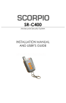
1
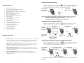
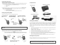
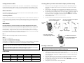
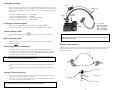
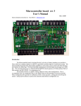
Setting Clock Time
1.
Enter the programming mode.
2.
3.
4.
Press button #4 repeatedly until the
icon begins to flash.
Press button #1 to select and enter clock setting mode.
Press button #1 to scroll through ‘hour’, ‘minute’, ‘am/pm’ settings. The selected
item will be flashing.
Press button #2 to adjust the setting of the selected item.
Press button #4 to save setting and exit, or press button #3 to abort.
5.
6.
Setting Alarm Clock
1.
Enter the programming mode.
2.
3.
4.
Press button #4 repeatedly until
icon begins to flash.
Press button #1 to select and enter alarm clock setting mode
Press button #1 to scroll through ‘alarm on/off’, ‘hour’, ‘minute’, ‘am/pm’
settings. The selected item will be flashing.
Press button #2 to adjust the setting of the selected item.
Press button #4 to save setting and exit, or press button #3 to abort.
5.
6.
FCC Notice
This device complies with Part 15 of FCC rules. Operation is subject to the following two
conditions: (1) This device may not cause harmful interference, and (2) This device
must accept any interference that may cause undesired operation.
Changes or modifications not expressly approved by the party responsible for
compliance could void the user’s authority to operate this device.
Aritronix Ltd
14435 N. Scottsdale Rd #500
Scottsdale, AZ 85254
Technical Assistance (480)951-1109
SR-i500
FM 2-Way Security System
INSTALLATION MANUAL
AND USER’S GUIDE
Selecting Auto/Manual Arming
Enter the programming mode. Scroll to the
icon and Press Button #1 to enter the
arming selection screen. The LCD will display the current setting ([Act] or [PAS]) and
the siren will chirp two or three times. To program follow these steps:
Standard Features
•
•
•
•
•
•
•
•
•
•
•
•
•
•
•
•
•
•
•
•
•
2-Way FM Transceiver
Alphanumeric LCD display with backlight
Ultra low power drain MCM
Built-in Analog Devices ADXL202 accelerometer
Ignition protection
Range Confirmation Signal (RCS)
Remote sensor control
Battery safeguard with “sleep mode”
Clock w/alarm
Violation display with time stamp
Passive arming
Selectable arming / disarming
Automatic reset
Flashing lights with memory display
Long range paging transmitter
Programmable multi-tone siren
Selectable siren duration
Arming confirmation
Low battery indication
Remote panic feature
Soft chirp arming
Perimeter sensor – A miniature multi stage microwave sensor that detects motion
in mass around the motorcycle, and uniquely protects its parts and accessories.
Detects any attempt to tamper with saddlebags, luggage or accessories.
•
Ignition disable and anti-hijack kit- Allows remote disabling of the motorcycle’s
electrical system, should someone force you off your bike. Also prevents the
engine from being started when the system is armed.
•
Back-up battery Transmitter–Built in back up power capacitors with voltage
sensing circuitry will ensure operation of the paging system even if wires are cut
or battery is disconnected.
•
Factory Connector Kits–OEM style connectors that simply plug into the
motorcycle’s factory wiring harness. Connector kits are available for select
motorcycle models.
2. Press button
#4 to save and
exit
When entering the arming program mode, the siren and turn signals will confirm the current mode
•
Manual arming- siren chirps 2 times, lights flash 2 times
•
Auto arming- siren chirps 3 times, lights flash 3 times (In this mode the system will
automatically arm itself 60 seconds after the ignition is turned off)
Selecting Siren Tone and Alarm Duration
Enter the programming mode. Scroll to the
icon and Press Button #1 to select.
The screen will display all of the sensor icons. To program follow these steps:
1. Press button
4 to scroll
between the
sensor icons
2. Press button 1
.
to select sensor
icon
Optional Accessories
•
1. Press button 2 to
toggle between
the alert options
3. Press button 1 to
toggle between
sound and duration
There are 5 siren tones
and 3 cycle duration
settings for ach sensor
5. Press button 4 to
save and exit
4. Press button 2
to adjust
Tone
Duration
Adjusting the ADL202 Accelerometer (Impact/Shock) Sensor
Enter the programming mode. Scroll to the
icon and press Button #1 to select.
The screen will display the current shock setting, and the siren will chirp 1-5 times to
confirm sensitivity level. To program follow these steps:
1. Press button 1 to
toggle between
On/Off and
sensitivity levels
2. Press button 2 to adjust.
Siren will chirp to confirm
sensitivity level 1-5
On/Off
3. Press button 4
to save and exit
Sensitivity Level
To test sensitivity bump motorcycle while in sensitivity adjustment mode, a siren chirp will indicate an
alarm trigger
1
10
Programming Instructions
There are two types of programming mode:
1) Programming the Transceiver- To program the transceiver the MCM does not have to
be installed or be within range. The programmable modes for the Transceiver are:
•
Transceiver Alert Type (Audible/Silent Vibrate).
•
Alarm Clock.
•
Clock.
Components List
Remote Transceiver
MCM (Main Control Module)
2) Programming the MCM- To program the MCM the system must be installed, with in
range, and in the disarmed mode. The programmable modes for the MCM are:
•
Auto/Manual Arming.
•
Siren Tones and Siren Duration.
•
Adjusting ADL202 Accelerometer (impact/shock sensor).
Entering Programming Mode
Accessory Harness
Follow the steps below to enter the programming mode:
1. Press button 4 twice to
enter programming
mode
2. Available programmable
options will be displayed.
The selected Icon will flash
Generic Instillation Kit (GEN-1)
3. Press button 4 repeatedly to
scroll though the programmable
icons
NOTE:
Press button 3 to
exit without
changing the
setting or saving
4. Press button 1 to
select icon and to begin
programming
Note. At any time during programming press button # 3 to exit without saving and return to the
main screen
Main Harness (HAR-1)
Planning the Installation
It is very important that before starting the installation of the security system, you carefully
read the installation instructions and spend time planning the installation. By planning
ahead you will be able to select the best approach in placing, securing and wiring the
system to your specific motorcycle. Although the installation is not difficult, there are a
number of steps that must be taken for the system to operate properly. We suggest the
following steps:
1.
2.
Selecting Transceiver Alert Type (Audible/Silent Vibrate)
1.
Enter programming mode. The
icon will begin to flash, press button #1 to
select. The LCD will display the current settings. To program follow these steps:
3.
4.
5.
6.
7
1. Press Button 2
to scroll
between the
alert options
2. Press button
4 to save and
exit
Alert options include: alert off, vibrate,
audible, vibrate and audible
9
Check that your motorcycle battery is fully charged and that all electrical circuits are
in good working condition.
Check the layout and construction of the motorcycle to decide what space is
available to place components.
Verify that no moving parts interfere with the components or their wires.
Do not route wires near sharp edges, which could cause a short.
Do not mount components near extreme heat areas such as exhaust pipes etc.
Allow at least an inch or two of slack at all connection points to reduce the chance
that a connection will break apart due to vibration.
Do not use a drill. Mount the components with the provided Velcro and cable ties.
Mounting the Components
Select a suitable location under the seat or in a side cover. Mount the MCM using Velcro
or cable ties. Make sure that it is not exposed or easily reached.
Note: Although the system will work in any position or mounting bangle, try to avoid placing the
MCM with the bell of the siren facing toward either side of the bike. This may reduce sensitivity
2
Checking Motorcycle Status and Violation Display with Time Stamp
Routing the Antenna Wire
The MCM includes an 18” antenna wire. The first 12” is a coaxial wire; the remaining 6” is
the actual antenna wire. When routing, try to avoid running the antenna along or near
metal. For best performance, try to have at least a portion of the antenna wire exposed.
Wire Connections
1.
3.
Press button #4. The back light and the memory screen will be displayed. If the
alarm was not triggered, all the sensor icons will come on and the # 0 0 will be
displayed.
If there was an alarm trigger, the last triggered sensor will flash. Press button #4
repeatedly to scroll through all the triggered sensors in the Transceiver’s memory.
The alternating numeric display shows the current trigger, numbering of triggers in
4.
5.
[03 05] + [A 8:55]
memory, and the time the trigger occurred. For Example:
means the tilt sensor was triggered. It was the 3rd sensor violated out of a total of
5 alarm triggers and the event occurred at 8:55am.
Press button #3 to exit.
To clear memory, press and hold down button #3 for 2 seconds.
2.
The MCM is equipped with two connectors. One is for the main harness (HAR-1) and the
other is for the optional accessories.
Accessory Harness
Plug in the accessory harness to the matching connector on the MCM. Note: each one of
the connectors on the accessory harness is unique and can only be connected into the
correct corresponding accessory. If no options are being used, plug in the supplied dust
cover.
If no alarm triggers in memory, all
sensor icons will be displayed
If the system was trigged, the last triggered
sensor will be displayed
Press button
4 once
Main Harness
If the optional factory connector kit is being used, please disregard this section of the
instructions and refer to the instructions that were supplied with the factory connector kit.
The main harness consists of two harnesses. One is labeled (HAR-1) and the second is
labeled (GEN-1). Plug in the white 4 pin connector from the (HAR-1) into the matching 4
pin connector from the (GEN-1). The (HAR-1) also has a waterproof connector that plugs
into the MCM. The wires should be connected as follows:
HAR-1
Black wire with fuse and ring terminal – To battery Positive (+).
Trigger #
Press button 4 repeatedly to
scroll though the trigger memory
If the turn signal lights do not flash, make sure that the Grey wires are connected to the turn signal
power (+) wires. Connecting these wires incorrectly may damage the system.
Honda
Kawasaki
Suzuki
Yamaha
Harley Davidson
Or, press and hold button 3 for 2
seconds to erase memory.
Encoding a Transceiver
Note: Transceivers are programmed from the factory. Encoding is only necessary should the
Transceiver looses its code and will not arm or disarm the security system.
1.
Color Codes:
Ground (-)
Green wire
Black wire
Black/White
Black wire
Black wire
Tail Light
Brown wire
Red wire
Brown wire
Blue wire
Blue wire
3
Left Turn Signal
Orange wire
Green wire
Green or Black
Green wire
Brown wire
Right Turn Signal
Blue wire
Grey wire
Grey wire
Brown wire
Purple wire
Time of trigger
Pres button 3 to exit and clear.
GEN-1
Black wire – To ground (-).
Grey wire – To turn signal power wire (Left).
Grey wire – To turn signal power wire (Right).
Orange wire – To tail light wire or any other wire that is hot (+) when ignition is “ON” (NOTE:
this is an input to the alarm this connection is not designed to flash the tail light).
Note: When the main harness (HAR-1) is plugged in, the siren should chirp and turn signals should
flash twice. If the siren dose not chirp; check the fuse, and battery (+) and ground (-) connections.
Total # of triggers
2.
3.
4.
5.
Plug in the MCM, the siren will chirp 2 times and the lights will flash 2 times. Within
6 seconds turn ignition switch “ON” and “OFF” 3 times.
If the sequence is done correctly and within the time allowed , the siren will chirp
2 times and the lights will flash an additional 2 times to confirm that the system is
in “Learn Mode”
Press and hold button # 1 for 5 seconds, system will chirp 2 times and the lights
will flash 2 times to indicate that the MCM has learned the code.
The Transceiver echoes 4 chirps and the LCD displays [LErn donE] to confirm that
the Transceiver is encoded.
Turn ignition “ON” and “OFF” to exit “Learn Mode”
8
Sensor Memory Display
Fuse
1.
When the system is disarmed the turn signals will flash to indicate if there has
been an alarm trigger. The lights will flash once to indicate that the system has
been disarmed, additional flashes indicate that the following trigger has
occurred:
1 flash then 1 additional flash =
1 flash then 2 additional flashes =
1 flash then 3 additional flashes =
1 flash then 5 additional flashes =
Shock Trigger
Tilt Trigger
Perimeter Sensor Trigger
Ignition Trigger
To Battery (+)
Accessory
Connector
HAR-1
RCS (Range Confirmation Signal)
GEN-1
1.
If the Transceiver is within range of the MCM the LCD displays
2.
If the Transceiver does not receive the RCS signal the
icon
Black – To Ground (-)
Grey – To Turn Signal
Grey – To Turn Signal
Orange – To Tail Light
MCM
icon will not appear.
Transceiver Battery Status
1.
The LCD will display 3 different
status.
icons to show the Transceivers battery
If the battery is to be removed, disconnect this connector first. Reconnect only after battery
terminals are reconnected.
Motorcycle Battery Status
1.
When the voltage on the motorcycle battery drops below 11.2 volts The LCD
displays
icon.
Battery Safeguard with “Sleep Mode”
1.
2.
NOTE:
Note: Connect the (HAR-1) harness to the MCM only after installation is completed.
If the alarm is armed for more than 30 days, it will automatically disable the
MCM’s receiver. In this mode the Transceiver will no longer be able to operate
the system. Note: In this mode, the system is still armed and protecting the bike.
To disarm, trigger the alarm, and press button #2.
Using the T-tap Connectors
1) Place female T-tap connector over wire to be tapped, close and squeeze until it snaps
close. 2) Now slip male T-tap connector over hinged end of the female connector to
make a connection.
Motorcycle Wire
1)
If the optional perimeter sensor is being used and the alarm is armed for more than 10 days
the system will automatically disable the perimeter sensor.
Locking the Transceiver’s buttons
1.
2.
To “lock”, press button #4 for 2 sec. The Transceiver will beep and buttons will
lock
To “unlock”, press button #4 for 2 sec. The Transceiver will beep and buttons will
unlock.
Female T-tap
2)
Female T-tap
Turning the Transceiver On/Off
1.
2.
To turn “off”, press button #4 for 4 seconds. The Transceiver will beep two times
to indicate that the unit has been turned “off”.
To turn “on”, press button #4 for 4 seconds. The Transceiver will beep two times
to indicate that the unit is turned back “on”.
Male T-tap
Motorcycle
Wire
Wire from (GEN-1)
Note: When the Transceiver is in the “Off” mode the clock will still be displayed
7
4
Operating Instructions
4.
If the perimeter sensor triggers a full alarm cycle, the LCD displays
(Note: The turn signal lights will not flash for a perimeter sensor trigger).
5.
With the optional back up system installed, the LCD displays
icon if the main
harness or battery power supply is disconnected. The MCM will still continue to
operate and transmit from its internal power source.
6.
The Transceiver will continue to flash the triggered icon until any button is pressed.
Arm
1.
Press button #1, siren chirps 3 times and the turn signal lights flash 1 time.
2.
The Transceiver echoes 3 chirps and the LCD displays
and
icons.
Disarm
1.
2.
Note: The Transceiver will sound a unique tone to correspond with the triggered sensor
Press button #2, siren chirps 1 time and lights flash 1 time.
The Transceiver echoes 1 chirp and the LCD displays
icon.
Remote Transceiver Icons and Massage Displays
Arming Without Perimeter Sensor (optional)
1.
Press button #3, siren chirps 4 times and turn signal lights flash 1 time.
2.
3.
The Transceiver echoes 4 chirps and the LCD displays ,
The system is armed but the Perimeter Sensor is disabled.
and
icons.
Arming Without Siren / Paging Only
1.
2.
3.
System Disarmed
System Armed
Alert Type Aud/Vibr
Silent Paging Only Arming
Signal Indicator
Perimeter Sensor Disabled
Button # 4
Battery Level Indicator
Shock Trigger
Ignition Trigger
Perimeter Trigger
Tilt Trigger
Press buttons #2 and #3 at the same time, siren chirps 6 times and the turn signal
lights flash 1 time.
Alarm Clock
Back up Power Activated
, and
icons.
The Transceiver echoes 6 chirps and the LCD displays ,
The system is armed but the siren, turn signal lights and perimeter sensor are
disabled.
Clock
Cycle Low Battery Indicator
Button #1
Button #2
Press buttons #1 and #3 at the same time, siren chirps 5 times and the turn signal
lights flash 1 time.
and
icons.
The Transceiver echoes 5 chirps and the LCD displays ,
The system is armed but the siren and turn signal lights are disabled for a silent
paging only alert.
Arming Without Siren or Perimeter Sensor (optional) / Paging Only
1.
2.
3.
Button #3
Panic/ Stop Trigger
1.
2.
When system is armed press button #3 for Panic feature.
Pressing button #3 during an alarm trigger stops the alarm cycle but keeps
the system armed.
Alarm Triggers
When the system is triggered, the siren will sound and the turn signal lights will flash. The
Transceiver’s LCD will display the following massages:
1.
If bike is bumped, the LCD displays
2.
If the bike is tilted, the LCD displays
3.
icon.
icon.
icon.
If the ignition switch is turned on or tampered with, the LCD displays
5
Icon.
6