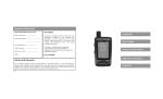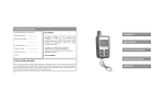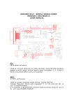
1
Limited Warranty
Limited Warranty
Products manufactured by Aritronix, Ltd are warranted by the company to the original consumer
purchaser to be free from defects in workmanship and materials. Should a product be found
defective, Aritronix shall repair or replace the product or any part of the product that Aritronix agrees
is defective without charge during the first 12 months from the date of original purchase if the
product is returned to Aritronix freight prepaid and accompanied by a copy of the purchase receipt.
This warranty does not apply to any product damaged by accident, physical or electrical misuse or
abuse, improper installation, alteration, any use contrary to its intended function, fire, flood,
unauthorized repair or any other acts of God.
Aritronix shall not be responsible for removal and/or reinstallation charges or theft of the motorcycle
or its contents or any incidental or consequential damages caused by any failure of the product to
function properly. Under no circumstances should this warranty or the product covered by warranty
be construed as an insurance policy against loss or damage of any kind.
Aritronix neither assumes nor authorizes any person or organization to make any warranties or assume
any liability in connection with the sale, installation, or use of this product.
This completes Aritronix warranty and no other warranty exists.
What should you do if you experience a problem with a Scorpio product?
First contact Aritronix, Ltd (Proof of purchase, installer and motorcycle information will be requested).
If after assistance from our trained staff it is determined that the Aritronix product may be faulty, then
you will be provided with detailed information on processing a warranty claim and instructions on
how to send the product into our repair office. All warranty claims must contain a return material
authorization (RMA). Aritronix will not accept any package that has not been approved for warranty
repair/exchange and been issued an RMA. Shipping charges may apply.
FCC Notice
This device complies with Part 15 of FCC rules. Operation is subject to the following two
conditions: (1) This device may not cause harmful interference, and (2) This device must
accept any interference that may cause undesired operation.
Changes or modifications not expressly approved by the party responsible for
compliance could void the user’s authority to operate this device.
For technical assistance, please contact Aritronix:
www.scorpioalarms.com
[email protected]
Toll Free
(800)428-0440
International
(480)951-1109
Aritronix Ltd
16055 N Dial Blvd B-10
Scottsdale, AZ 85260
SR-i800
Motorcycle Security System
INSTALLATION MANUAL
AND USER’S GUIDE
Troubleshooting Guide
Table of Contents
Installation
•
Component List ---------------------------------------------------------------•
Planning The Installation ---------------------------------------------------•
Mounting The Components ----------------------------------------------•
Color Codes --------------------------------------------------------------------•
Connections --------------------------------------------------------------------•
Using the T-tap ------------------------------------------------------------------
Page 3
Page 3
Page 4
Page 5
Page 5
Page 6
User’s Guide
•
Standard Features -----------------------------------------------------------•
Transceiver Battery -----------------------------------------------------------•
Violation Display --------------------------------------------------------------•
Operating the transceiver -------------------------------------------------•
Adjusting G Sensor -----------------------------------------------------------•
Selecting Arming Modes ---------------------------------------------------•
Alarm Triggers ------------------------------------------------------------------•
Manual Override Code ----------------------------------------------------•
Encoding a Transceiver ----------------------------------------------------•
Troubleshooting Guide -------------------------------------------------------
Page 2
Page 3
Page 6
Page 7
Page 7
Page 7
Page 8
Page 8
Page 1
Page 10
Accessories
•
Optional Accessories -----------------------------------------------------•
Perimeter Sensor (SN-5) ------------------------------------------------------
Page 2
Page 9
Warranty and FCC Information
•
Limited Warranty ------------------------------------------------------------•
FCC Notice ---------------------------------------------------------------------•
Contact information ----------------------------------------------------------
Page 11
Page 11
Page 11
Encoding a Transceiver
Note: The transceivers are programmed from the factory. Encoding is only necessary should
the transceiver lose its code and will not arm or disarm the security system or if a
replacement remote is obtained.
1.
2.
3.
4.
5.
Unplug HAR-1 from the MCM-9 and plug it back in, the siren will chirp 2 times and
the lights will flash 2 times.
Within 6 seconds of plugging in the HAR-1, turn ignition switch “ON” and “OFF” 3
times.
If step 2 is done correctly and within the time allowed , the siren will chirp 2 times
and the lights will flash an additional 2 times to confirm that the system is in
“Learn Mode”.
Press and hold the button until the system chirps 2 times and the lights flash 2
times to indicate that the MCM has learned the code.
Turn ignition “ON” and “OFF” to exit “Learn Mode”.
**It is not recommended to clip the remote to your ignition key. Attaching the
remote to your key may damage the remote and/or scratch your bike**
1
10
Perimeter Sensor (SN-5)
Mounting the SN-5 Perimeter Sensor
The Perimeter Sensor uses high frequency microwave technology to detect mass density
movement around the motorcycle. The signal can transmit through the seat, fiberglass,
leather and plastic, but not metal. It is recommended to place this sensor under the seat
as close as possible to the center of the motorcycle. With the provided Velcro, you can
mount this sensor on top of the battery or any flat surface, making sure that the top side of
the sensor is facing upwards. To prevent false perimeter alerts, ensure the perimeter sensor
is at least 3-4 inches away from the MCM.
Adjusting the Perimeter Sensor
Although the perimeter sensor is pre-set from the factory, it may be necessary to adjust the
sensitivity to suit your specific application.
1.
Stand at least 10’ away from the motorcycle and arm the system.
2.
With the remote outside of RFID range, walk towards the motorcycle and try to lean
over the top of it. Once the sensor detects movement, the siren will begin to chirp
slowly. If you back away from the motorcycle, the siren will stop chirping. If you
continue to move closer to the motorcycle, the siren will start to chirp faster with 2
additional stages and then go into a full alarm trigger.
3.
Sensitivity can be adjusted by removing the plastic cap counter clockwise and tuning
the adjustment screw. To increase sensitivity, turn adjustment screw clockwise. To
decrease sensitivity, turn the adjustment screw counter clockwise.
4.
The Perimeter sensor has an internal tuning control, which has been set at the factory.
This tuning control should only be changed if the sensor can not be properly set as
described in #3 above, please call Aritronix technical support.
Standard Features
•
•
•
•
•
•
•
•
•
•
•
•
•
•
Ultra low power drain MCM
Built-in Analog Devices accelerometer
Remote sensor control
Battery safeguard with “sleep mode”
Violation display
Selectable auto/ manual arming / disarming
Flashes signal lights
Integrated 120 dB multi-tone siren
Remote panic feature
Soft chirp arming
Selectable Perimeter Sensor arming
Flash input for diagnostics and possible future upgrades
Programmable override code to disarm alarm
Built in back up battery
Optional Accessories
•
Ignition Disable - Prevents the engine from being started when the system is
•
Perimeter Sensor - Three-Stage Perimeter Sensor
•
Factory Connector Kits – OEM style connectors that simply plug into the
armed and the remote is not within RFID range.
Note: Do not turn sensitivity above half way. Doing so may cause false alarms.
Plastic Cap:
Remove to
adjust sensitivity
motorcycle’s factory wiring harness. Connector kits are available for select
motorcycle models.
To Accessory Harness on
Main Control Module (MCM)
9
2
Components List
MCM (Main Control Module)
Alarm Triggers
1. If the bike is shocked, the siren will sound for 5 seconds and the turn signal lights will flash.
2. If the bike is tilted, the siren will sound for 30 seconds and the turn signal lights will flash.
3. If the ignition switch is turned on with the remote not present, the siren will sound for 30
seconds and the turn signal lights will flash.
* Remote Transceiver
Note: Once an alarm trigger has occurred and the siren duration is completed, the system will remain
armed and accept any additional triggers.
Generic Installation Kit (GEN-1)
Accessory Harness (ACC-1)
Manual Override Procedure
Programming Personal Override code
A personal override code will be a sequence of left – right – left - right turn signal flashes
that can be used if the remote is lost to disable the alarm:
Main Harness (HAR-1)
RFID Module
Enter Programming Mode
1.
2.
3.
Manually disarm system by quickly double pressing the remote button.
(From the off position) - Turn ignition on – off – on – off – on.
Press and hold the button until the siren chirps 3 times.
Select number of flashes for the Manual Override Code
The code will be a combination of left-right-left-right turn signal counts.
*This remote transceiver uses a CR2032 battery. To replace the battery, pry the cases
apart using a flathead screwdriver at the small end of the remote. Then slide the
screwdriver towards the button until the case halves come apart. Now pull the circuit
board out of the rear case half and replace the battery. Last part is to snap the circuit
board back into the rear case and the two case halves back together and you’re done.
1.
2.
3.
4.
5.
Turn on left turn signal to desired number of flashes. (up to 9)
Turn on right turn signal to desired number of flashes. (up to 9)
Turn on left turn signal to desired number of flashes. (up to 9)
Turn on right turn signal once to exit mode. (Will only register one flash.)
The bike will flash the code in the same sequence entered.
*This feature is not compatible with every motorcycle on the market.
*Some bikes are easier than others to program and operate this
feature, make sure to test the code once it is programmed.
Planning the Installation
It is very important that before starting the installation of the security system, you carefully
read the installation instructions and spend time planning the installation. By planning
ahead, you will be able to select the best approach in placing, securing and wiring the
system to your specific motorcycle. Although the installation is not difficult, there are a
number of steps that must be taken for the system to operate properly. We suggest you
read the steps on the following page.
3
Using the Manual Override Code in case of lost remote or if the battery is depleted
1.
2.
3.
Turn ignition key to the on position. Let alarm go thru a full cycle until the turn
signal lights stop flashing. (If siren is turned off, you do not need to wait for a full
cycle)
Enter the Manual Override Code as originally programmed.
When correct code is entered, the alarm will deactivate.
8
Operation Instructions (Cont.)
Planning the Installation (Cont.)
Selecting Arming Modes
1.
The SR-i800 can be manually armed and disarmed by using the button on the remote or
automatically armed and disarmed by turning your ignition key on and off. When the
alarm is first installed, the alarm will arm 5 seconds after the HAR-1 harness is installed. The
default setting is to arm with the perimeter sensor (SN-5) on.
Automatic Arming - By keeping the remote with you and turning your key on, the alarm will
recognize the remote and disarm the alarm. Once you turn the key off, the alarm will wait
5 seconds and arm again.
Manual Arming - Press and hold the button for 1 second. When you manually disarm the
alarm, you are turning the auto arm feature off. To turn auto arming back on, simply arm
the alarm with the remote and go back to using the key to arm and disarm.
Manual Arming with Perimeter Sensor - Press and hold the button for 5 seconds. The turn
signals will flash normally then will flash left-right twice to confirm the system is armed with
the Perimeter Sensor active.
Manual Disarming - While armed, double tap the button on your remote and the alarm will
chirp and flash the turn signal lights 1 time. Now the alarm is manually disarmed and will
not automatically arm. After manually disarming, the alarm will only arm when you press
and hold the button on the remote for 1 second. To reenable the automatic arming
feature, simply arm the alarm and go back to using the key.
Setting the Perimeter Sensor Default
1. To select between perimeter sensor on and off, you must first double tap the
button on the remote quickly to manually disarm the alarm.
2. Turn your ignition key on-off-on then double tap the button quickly and the
siren should chirp 2 or 3 times to let you know whether the perimeter sensor is
on or off. Double tap again to change current setting.
Perimeter On: 2 Chirps
Perimeter Off: 3 Chirps
3. Turn your ignition key off to save and exit program mode.
4. Manually arming the Perimeter Sensor will not change the default. The next
time the system arms automatically, it will go back to the default setting.
(see Arming with Perimeter Sensor above)
Adjusting G Sensor Sensitivity (Shock and Tilt Triggers)
The sensitivity is based on a scale from 1-5 indicated by 1-5 chirps or
turn signal flashes with 5 being most sensitive setting available.
Note:
1.
2.
3.
4.
If the perimeter sensor is armed for more than 10 days, the battery safeguard will
automatically disable the perimeter sensor.
Manually disarm the alarm by double tapping the button.
Turn your ignition key on-off-on and then hold the button, the siren should chirp to
let you know its current sensitivity level. (Default level is 3)
Press the button on the remote to change sensitivity.
Turn ignition key off to save the setting and exit. The siren will give chirp once to
indicate the save was successful.
7
2.
3.
4.
5.
6.
7
Check that your motorcycle battery is fully charged and that all electrical circuits are
in good working condition.
Check the layout and construction of the motorcycle to decide where space is
available to place the components.
Verify that no moving parts interfere with the components or their wires.
Do not route wires near sharp edges, which could cut wires and cause a short.
Do not mount components near extreme heat areas such as exhaust pipes
Allow at least an inch or two of slack at all connection points to reduce the chance
that a connection will break apart due to vibration.
Do not drill any holes; mount the components with the provided Velcro and cable ties.
Mounting the Components
Note: Although the system will work in any position or mounting angle, try to avoid placing the
MCM with the bell of the siren facing toward either side of the bike; this may reduce sensitivity.
Select a suitable location under the seat or in a side cover. Mount the MCM using Velcro
or cable ties. Make sure that it is not exposed or easily reached.
Routing the RFID Antenna
Make sure to place the RFID antenna as close as possible to where the remote will be
when you are turning your key on to disarm the alarm. The RFID range depending on
obstructions is 2-3 feet.
Routing the Antenna Wire
The MCM includes an 18” antenna wire. The first 12” is a coaxial wire; the remaining 6” is
the actual antenna wire. When routing, try to avoid running the antenna along or near
metal. For best performance, try to have at least a portion of the antenna wire exposed.
Wire Connections
The MCM is equipped with two connectors. One is for the main harness (HAR-1) and the
other is for the optional accessories.
Accessory Harness
Plug in the accessory harness to the center port on the MCM. Each one of the
connectors on the accessory harness is unique and can only be connected to the correct
accessory. If no options are being used, plug in the supplied dust cover.
4
Main Harness
If the optional factory connector kit is being used, please disregard this section of the
instructions and refer to the instructions that were supplied with the factory connector kit.
Note: Connect the (HAR-1) harness to the MCM only after installation is completed.
If the battery is to be removed, disconnect this connector first. Reconnect only after battery
terminals are reconnected.
The main harness consists of two harnesses. One is labeled (HAR-1) and the second is
labeled (GEN-1). Plug in the white 4 pin connector from the (HAR-1) into the matching 4
pin connector from the (GEN-1). The (HAR-1) also has a waterproof connector that plugs
into the MCM. The wires should be connected as follows:
Using the T-tap Connectors
HAR-1
Black wire with fuse and ring terminal – To battery Positive (+).
1) Place female T-tap connector over wire to be tapped, close and squeeze until it snaps.
2) Now slip male T-tap connector over hinged end of the female connector.
GEN-1
Black wire – To ground (-).
Grey wire – To turn signal power wire (Left).
Grey wire – To turn signal power wire (Right).
Orange wire – To tail light wire OR any other wire that is hot (+) when ignition is ON (NOTE:
this is an input to the alarm this connection is not designed to flash the tail light).
Note: When the main harness (HAR-1) is plugged in, the siren should chirp twice and turn signals
should flash. If the siren does not chirp; check the fuse, battery power (+) and ground (-)
connections.
If the turn signal lights do not flash, make sure that the grey wires are connected to the turn signal
power (+) wires. Connecting these wires incorrectly may damage the system.
*** Turn Signal wires will pulse 12V. If your turn signals are LED based, use
caution when installing or contact Aritronix Support for assistance***
1)
Motorcycle Wire
Female T-tap
2)
Female T-tap
Male T-tap
Motorcycle
Wire
Wire from (GEN-1)
Color Codes:
Honda
Kawasaki
Suzuki
Yamaha
Harley Davidson
Ducati
Ground (-)
Green wire
Black wire
Black/White
Black wire
Black wire
Black wire
Tail Light
Brown wire
Red wire
Brown wire
Blue wire
Blue wire
Yellow wire
Left Turn Signal
Orange wire
Green wire
Green or Black
Green wire
Brown wire
White/Black wire
Right Turn Signal
Blue wire
Grey wire
Grey wire
Brown wire
Purple wire
White/Green wire
Fuse
To Battery (+)
HAR-1
Accessory
Connector
Operation Instructions
Violation Display
When the system is disarmed, the turn signals will flash to indicate that there has been an
alarm trigger. The lights will flash once to indicate that the system has been disarmed and
additional flashes indicate the following trigger has occurred:
1 flash then 1 additional flash =
1 flash then 2 additional flashes =
1 flash then 3 additional flashes =
1 flash then 5 additional flashes =
Shock Trigger
Tilt Trigger
Perimeter Sensor Trigger
Ignition Trigger
GEN-1
Black – To Ground (-)
Grey – To Turn Signal
Grey – To Turn Signal
Orange – To Tail Light
MCM
5
6