1
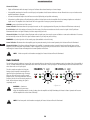
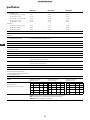
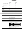
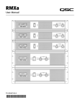
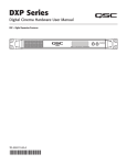
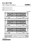
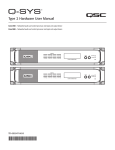
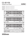
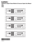
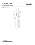
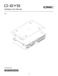
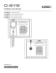
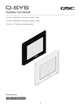
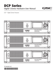
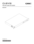
RMXa
User Manual
TD-000407-00-A
*TD-000407-00*
EXPLANATION OF SYMBOLS
The term “WARNING!” indicates instructions regarding personal safety. If the instructions are not followed the result may be bodily injury or death.
The term “CAUTION!” indicates instructions regarding possible damage to physical equipment. If these instructions are not followed, it may result in
damage to the equipment that may not be covered under the warranty.
The term “IMPORTANT!” indicates instructions or information that are vital to the successful completion of the procedure.
The term "NOTE" is used to indicate additional useful information.
The intent of the lightning flash with arrowhead symbol in a triangle is to alert the user to the presence of un-insulated "dangerous"
voltage within the product's enclosure that may be of sufficient magnitude to constitute a risk of electric shock to humans.
The intent of the exclamation point within an equilateral triangle is to alert the user to the presence of important safety, and operating
and maintenance instructions in this manual.
IMPORTANT SAFETY INSTRUCTIONS
EN
WARNING!: TO PREVENT FIRE OR ELECTRIC SHOCK, DO NOT EXPOSE THIS EQUIPMENT TO RAIN OR MOISTURE.
• Keep these instructions.
• Heed all warnings.
• Follow all instructions.
• Do not use this apparatus near water.
• Clean only with a dry cloth.
• Do not block any ventilation opening. Install in accordance with the manufacturer's instructions.
• Do not install near any heat sources such as radiators, heat registers, stoves, or other apparatus (including amplifiers) that produce heat.
• Do not defeat the safety purpose of the polarized or grounding-type plug. A polarized plug has two blades with one wider than the other. A
grounding type plug has two blades and a third grounding prong. The wide blade or the third prong are provided for your safety. If the provided
plug does not fit into your outlet, consult an electrician for replacement of the obsolete outlet.
• Protect the power cord from being walked on or pinched particularly at plugs, convenience receptacles, and the point where they exit from
the apparatus.
• Only use attachments/accessories specified by the manufacturer.
• Unplug this apparatus during lightning storms or when unused for long periods of time.
• Refer all servicing to qualified service personnel. Servicing is required when the apparatus has been damaged in any way, such as power-supply
cord or plug is damaged, liquid has been spilled or objects have fallen into the apparatus, the apparatus has been exposed to rain or moisture,
does not operate normally, or has been dropped.
• The appliance coupler, or the AC Mains plug, is the AC mains disconnect device and shall remain readily operable after installation. On units
equipped with powerCon® connectors, the AC Mains disconnect device is the AC Mains plug only; do not use the appliance coupler.
• Adhere to all applicable, local codes.
• Consult a licensed, professional engineer when any doubt or questions arise regarding a physical equipment installation.
2
RoHS Statement
The RMXa products are in compliance with European Directive 2002/95/EC – Restriction of Hazardous Substances (RoHS).
The RMXa products are in compliance with “China RoHS” directives. The following chart is provided for product use in China and its territories:
RMXa
有毒有害物质或元素
部件名称
(Part Name)
电路板组件
(PCB Assemblies)
机壳装配件
(Chassis Assemblies)
(Toxic or hazardous Substances and Elements )
铅
汞
镉
六价铬
多溴联苯
多溴二苯醚
(Pb)
(Hg)
(Cd)
(Cr(vi))
(PBB)
(PBDE)
X
O
X
O
O
O
X
O
X
O
O
O
O: 表明这些有毒或有害物质在部件使用的同类材料中的含量是在 SJ/T11363_2006极限的要求之下。
EN
O: Indicates that this toxic or hazardous substance contained in all of the homogeneous materials for this part is below the limit requirement in SJ/
T11363-2006.
X: 表明这些有毒或有害物质在部件使用的同类材料中至少有一种而含量是在SJ/T11363_2006极限的要求之上。
X: Indicates that this toxic or hazardous substance contained in at least one of the homogeneous materials used for this part is above the limit
requirement in SJ/T11363-2006.
FCC Statement
NOTE: This equipment has been tested and found to comply with the limits for a Class B digital device, pursuant to Part 15 of the
FCC Rules.
NOTE: These limits are designed to provide reasonable protection against harmful interference in a residential installation. This
equipment generates, uses and can radiate radio frequency energy and, if not installed and used in accordance with the instructions,
may cause harmful interference to radio communications. However, there is no guarantee that interference will not occur in a particular
installation. If this equipment does cause harmful interference to radio or television reception, which can be determined by turning the
equipment off and on, the user is encouraged to try to correct the interference by one or more of the following measures:
• Reorient or relocate the receiving antenna.
• Increase the separation between the equipment and receiver.
• Connect the equipment into an outlet on a circuit different from that to which the receiver is connected.
• Consult the dealer or an experienced radio/TV technician for help.
3
Warranty (USA only; other countries, see your dealer or distributor)
QSC Audio Products 3-Year Limited Warranty
QSC Audio Products, LLC (”QSC”) guarantees its products to be free from defective material and/or workmanship and will replace defective parts
and repair malfunctioning products under this warranty when the defect occurs under normal installation and use, provided the unit is returned to
our factory, one of our authorized service stations or an authorized QSC International Distributor via pre-paid transportation with a copy of proof
of purchase (i.e., sales receipt). This warranty provides that the examination of the return product must indicate, in our judgment, a manufacturing
defect. This warranty does not extend to any product which has been subjected to misuse, neglect, accident, improper installation, or where the
date code has been removed or defaced. QSC shall not be liable for incidental and/or consequential damages. This warranty gives you specific legal
rights. This limited warranty is freely transferable during the term of the warranty period. The warranty on QSC products is NOT VALID if the products
have been purchased from an unauthorized dealer/online e-tailer, or if the original factory serial number has been removed, defaced, or replaced in
any way. Damage to, or loss of any software or data residing on the product is not covered. When providing repair or replacement service, QSC will
use reasonable efforts to reinstall the product’s original software configuration and subsequent update releases, but will not provide any recovery or
transfer of software or data contained on the serviced unit not originally included in the product.
Customers may have additional rights, which vary from state to state or from country to country. In the event that a provision of this limited warranty is
void, prohibited or superseded by local laws, the remaining provisions shall remain in effect.
EN
The QSC limited warranty is valid for a period of three (3) years from date of purchase in the United States and many (but not all)
other countries.
For QSC warranty information in countries other than the United States, contact your authorized QSC international distributor. A list of QSC
International distributors is available at www.qsc.com.
To register your QSC product online, go to www.qsc.com and select ”Product Registration”. Other questions regarding this warranty can be answered
by calling, e-mailing or contacting your authorized QSC distributor.
Phone: 1-800-854-4079 within US and Canada, +1-714-754-6175 international, Email: [email protected], Website: www.qsc.com.
4
Key Features
•
•
•
•
•
•
•
2 channels
XLR, TRS, and barrier strip screw terminal input connectors
NL4 and binding post output connectors
Each channel has independent Clip Limiter and Low Frequency Filter (30 or 50 Hz)
Stereo, Bridge Mono, and Parallel modes of operation
QSC reliability
Complete amplifier protection
Controls, Connectors & Features
The illustrations below are for the RMX 5050a which is similar to the RMX 4050a. The 2RU units do not have the Protect Mode indicator (#5).
1
2
3
4
3
4
5
6
EN
— Figure 1 —
1. Power On indicator
3. Clip and Signal indicators
5. Protect mode indicator
2. Power switch
4. Gain controls
6. Cooling air exhaust vents indicator
1
2
3
4
5
6
7
8
9 10
— Figure 2 —
1. Barrier strip input connectors
5. Cooling fan
9. AC circuit breakers
2. XLR input connectors
6. NL4 output connectors
10.IEC power inlet (power cord connector)
3. TRS (1/4”) input connectors
7. Binding post output connectors
4. Mode switches and settings
8. Serial number label
5
Unpacking
1. RMX amplifier
4. Rear rack ear mounting kit
2. Quick Start Guide
5. IEC-type detachable power cord
3. Adhesive rubber feet (for non-rack mount applications)
Rack Mounting
Use four screws and washers to mount the amplifier to the equipment rack rails. To use the amplifier outside a rack, attach the self-adhesive rubber
feet to the bottom. Use the rear rack ear support kit to support the rear of the amplifier for portable use.
When installing equipment into a rack, distribute the units evenly. Otherwise, hazardous conditions may be created by an uneven weight distribution.
Cooling
Air flows from the rack, into the back of the amplifier, and out the front. This keeps the rack cool. The fan automatically runs faster when the amp is
working hard.
EN
Air flow in QSC amplifiers: Cool air is drawn into the rear of the amplifier by the cooling fan. Warm air exits the front of the amplifier.
CAUTION!: Do not block the front or rear air vents!
— Figure 3 —
AC Mains
Connect AC power to the IEC socket on the back of the amplifier. NOTE: Turn off the AC power switch before connecting AC power.
WARNING!: The correct AC line voltage is shown on the serial number label, on the rear panel. Connecting to the wrong line
voltage may damage the amplifier or increase the risk of electric shock.
Setting The Mode Switches
The RMX 4050a and RMX5050a have Mode switches for Stereo, Parallel, or Bridge Mode. Additionally, each channel has independent Clip Limiting
and Low Frequency (LF) Filtering.
Setting Clip Limiters
Each channel has a Clip Limiter with its own on-off switch. The limiter only responds to actual clipping, and automatically
compensates for load and voltage variations. Clip limiting is generally recommended, especially to protect high
frequency drivers.
• Set switch to the right to use Clip Limiting.
• Switch 1 controls Channel 1.
• Switch 10 controls Channel 2.
— Figure 4 —
6
Selecting Stereo, Parallel, Or Bridge Mode
The amplifier can be set for normal Stereo operation, Parallel input Mode, or Bridge Mono Mode.
Stereo Mode- Each channel remains independent. The amplifier may be used for two different signals.
Stereo Mode - Switches 4, 5, 6 and 7 are all set to the LEFT position.
Parallel Mode - This setting connects both inputs together. One signal feeds both channels. Each
channel's Gain control and loudspeaker connection remain independent.
Parallel Mode - Switches 4, and 5, are set to the RIGHT position. Switch 6 and 7 are set to the LEFT
position
Bridge Mode- This setting combines both channels into a single channel with twice the output power. Use
only the first channel's input and Gain control. Set the second channel's Gain control at minimum. The load
must be rated for the higher output power, and is connected as shown in the Outputs section.
Bridge Mode- Switches 4, 5, 6,7 and 8 are all set to the RIGHT position and Switch 10 is set to the LEFT
position.
EN
— Figure 5 —
— Figure 6 —
CAUTION!: Do not connect different inputs to each side of a channel pair
when operating in Parallel or Bridge Mode.
Setting Low Frequency Filters
Each channel has a 12dB per octave Low Frequency Filter to prevent cone overexcursion,
making more power available for the loudspeaker’s rated frequency range. This reduces
distortion and prevents amplifier overload.
The Filter should only be turned off for driving subwoofers with special low frequency
capability. Otherwise, unless you have filtering in the signal path preceding the amplifier,
use the Low Frequency Filter. The loudspeaker’s documentation will specify the low
frequency limit.
Each channel has its own switches for LF Filter on/off and frequency selection.
USE CH1 INPUT, CLIP LIM, AND
FILTERS. USE CH1 GAIN CONTROL
TO ADJUST LEVEL. SWITCH OFF
THE CH2 CLIP LIMAND FILTER.
SET CH2 GAIN OFF (-∞ ).
USE THE BRIDGE MONO SPEAKER
CONNECTION.
— Figure 7 —
• Channel 1 uses switches 2,3.
• Channel 2 uses switches 8,9.
• Switches 3 and 8 turn the LF Filter ON.
• Switches 2 and 9 select 30Hz or 50 Hz.
— Figure 8 —
7
Barrier Strip Inputs
Each channel has a balanced 3-terminal input. Wiring is connected with simple hand tools, and inputs can be changed quickly.
The input impedance is 20k ohm balanced or 10k ohm unbalanced.
Balanced connections are recommended to reduce AC hum and interference, especially with long cable runs. Unbalanced connections may be
suitable for short cables. The signal's source impedance should be less than 600 ohms.
Balanced inputs: Strip the wires ¼ inch (6 mm) and connect to the terminals as shown. Be sure to tighten the screws firmly. (See Figure 9)
If unbalanced connections are required, connect a jumper wire between the minus (-) terminal and the ground terminal. Then connect the input
signal to the positive (+) terminal and the shield to the minus or ground terminal.
Unbalanced inputs: Strip the wire ¼ inch and connect a jumper wire between the minus (-) terminal and the ground terminal. Then connect the input
signal to the positive (+) terminal and the shield to the minus or ground terminal, as shown. Be sure to tighten the screws firmly. (See Figure 10)
EN
— Figure 9 —
— Figure 10 —
XLR and TRS (1/4”) Inputs
Each channel has a balanced 3-terminal XLR and TRS input. Inputs are connected with standard
cables and can be changed quickly. Pinouts are marked on the rear panel and shown in
the illustration.
The input impedance is 20k ohm balanced or 10k ohm unbalanced.
INPUT IMPEDANCE:
20K BALANCED
10K UNBALANCED
Balanced connections are recommended to reduce AC hum and interference, especially with long
cable runs. Unbalanced connections may be suitable for short cables. The signal's source impedance
should be less than 600 ohms.
Unbalanced TRS connectors (2-terminal) automatically connect the minus (-) terminal to ground
when inserted.
— Figure 11 —
8
Outputs
• Wiring connections are shown on the back of the chassis.
• Binding Post Outputs
• Stereo and Parallel Mode: Wire as shown by loudspeaker symbols 1 and 2.
• Bridge Mode: Wire as shown by Bridge Mono loudspeaker symbol.
NL4 Outputs
Each channel accepts a normal 2-wire cable. In addition, Channel 1 accepts 4-wire cables for single
cable stereo or bi-amp connection.
WARNING!: OUTPUT TERMINAL SAFETY WARNING! Do not touch output
terminals while amplifier power is on. Make all connections with amplifier
turned off. Risk of hazardous energy!
— Figure 12 —
WARNING!: Stereo and Parallel Mode- Connect each loudspeaker to its own channel of the amplifier, as shown on the
left side of the chassis label. The Mode configuration switches must be set for Stereo or Parallel Mode.
EN
Bridge Mode- Bridge Mode configures the channel pair to drive a single audio circuit. The Mode configuration switches must be set for
Bridge Mode.
Connect the load as shown on the right side of the binding posts or to the left on Channel 1’s NL4. 4 ohms is the minimum impedance for Bridge
Mode use.
CAUTION!: Do not use less than 4 ohm load in Bridge Mode! Note polarity of connection for Bridge Mode.
CAUTION!: OUTPUT WIRING WARNING: CLASS 2 WIRING SHALL BE USED. FOR BRIDGED MONO MODE, CLASS 3 WIRING SHALL
BE USED.
LED Indicators
The LED indicators can be used to monitor system operation and identify common problems.
POWER: A single blue indicator, on left side of AC power switch.
Normal indication: AC switch ON: indicator
will illuminate.
If no indication: Check AC power cord and AC
outlet. Check rear panel circuit breakers.
CLIP: red
Normal indication: Illuminates whenever the
amplifier is driven beyond full power. The LED’s
brightness indicates the amount of distortion.
Distortion that causes only brief flashing may
not be audible. During muting, the indicator
fully illuminates. This occurs during normal
“On‑Off” muting.
— Figure 13 —
9
Abnormal indication:
• Bright red illumination while the amp is being used indicates either thermal muting or a shorted output.
• If the amplifier overheats, the fan will run at full speed, and operation should resume within one minute. Allow the fan to run, and make sure the
amplifier ventilation is adequate.
• A shorted or overloaded output circuit will cause excessive Clip flashing and possible overheating.
• If distortion is audible without a Clip indication, the problem is either before or after the amplifier. Check for damaged speakers or overloaded
signal source. The amplifier Gain control should be in the upper half of its range to prevent input overload.
SIGNAL: green, to the left of each Gain control.
Normal indication: illuminates when the input signal exceeds -35 dB. As signal approaches full power, the indicator will illuminate continuously.
If no indication: check Gain settings and increase Gain if necessary. Check input connections and audio source for signal. If the Clip indicator
illuminates with little or no Signal indication, check the output wiring for shorts.
Abnormal indication: If the Signal indicator illuminates with no signal input, there may be system oscillations or some other malfunction. Disconnect
the load and fully reduce the Gain. If the signal indicator remains on, the amp may need servicing.
PROTECT: red, on the right side of Gain control group. (Not available on the 2RU Units)
Normal indication: illuminates when the amplifier goes into protective muting. Under normal operation, this indicator will not be illuminated.
EN
Abnormal indication: If the Protect indicator illuminates, the amplifier is in protective muting. Leave the Power On to allow the fan to cool the
amplifier. Check the rear panel circuit breakers; if either is tripped, reset it by pushing on the center of the control. When the amplifier has cooled
sufficiently, the Protect indicator will extinguish and normal operation will resume.
NOTE: If both rear panel circuit breakers are tripped, the Protect indicator will not be illuminated.
Gain Controls
Turn the Gain controls clockwise to increase Gain and counterclockwise to decrease Gain. At the maximum setting, the voltage Gain of the amplifier is
+36 dB. The RMX 4050a will produce 800 watts into 8 ohms when driven with a 1.26V input signal. The RMX 5050a produce 1050 watts into 8 ohms
when driven with a 1.42V input signal.
The Gain controls are marked in dB of gain.
Settings should normally be made within the
upper half of the adjustment range. The range
below 22 dB should not be used for normal
program levels, as the input headroom could be
exceeded, but can be used for testing at reduced
levels. At the minimum setting, the signal is
completely cut off.
— Figure 14 —
CAUTION!: Continuous
operation at high power may
trigger the thermal protection circuitry, shutting down the amplifier and fully illuminating the Protect indicator. Operation will resume
after the amplifier has cooled down sufficiently.
NOTE: If both rear panel circuit breakers are tripped, the Protect indicator will not be illuminated.
10
Specifications
OUTPUT POWER in watts
8Ω / FTC 20 Hz - 20 kHz / 0.1% THD
8Ω / EIA 1 KHZ / 0.1% THD
4Ω / FTC 20 HZ - 20 KHZ / 0.1% THD
4Ω / EIA 1 KHZ / 0.5% THD
2Ω / EIA 1 KHZ / 1% THD
Bridge Mode
8Ω / FTC 20 Hz - 20 kHz / 0.1%THD
8Ω / EIA 1 kHz / 0.1%THD
4Ω / EIA 1 kHz / 1%THD
EN
RMX 850a
RMX 1450a
RMX 2450a
185 W
200 W
280 W
300 W
430 W
260 W
300 W
400 W
500 W
700 W
450 W
500 W
650 W
800 W
1200 W
530 W
600 W
830 W
800 W
900 W
1400 W
1300 W
1500 W
2400 W
DYNAMIC HEADROOM
2 dB @ 4 ohms
DISTORTION
SMPTE-IM
<0.01%
FREQUENCY RESPONSE
(at 10 dB below rated output power)
20 Hz to 20 kHz, 8 ohms, LF Filter bypassed: +0, -1 dB
5 Hz to 50 kHz, 8 ohms, LF Filter bypassed: +0, -3 dB
DAMPING FACTOR
>300 @ 8 OHMS
NOISE (unweighted)
100 dB below rated output from 20 Hz to 20 kHz
VOLTAGE GAIN
31.6x (30 dB)
40x (32 dB)
50x (34 dB)
INPUT SENSITIVITY, V RMS
full rated power @ 8 ohms
1.15 Vrms (+3.4 dBu)
1.15 Vrms (+3.4 dBu)
1.23 Vrms (+4.0 dBu)
INPUT IMPEDANCE (all models)
20 kΩ balanced / 10 kΩ unbalanced
CONTROLS (all models)
Front: AC switch, Ch. 1 and Ch. 2 gain / Rear: 10-position DIP switch
INDICATORS (all models)
POWER: Blue LED / CLIP: Red LED, 1 per channel / SIGNAL: Green LED, 1 per channel
CONNECTORS (all models)
Input: Active balanced; XLR and ¼" (6.3 mm) TRS and barrier strip
Output: “Touch-Proof” binding posts and NL4
COOLING (all models)
Continuously variable speed fan, back-to-front air flow
Stable into reactive or mismatched loads
AMPLIFIER PROTECTION (all models)
Full short circuit, open circuit, thermal, ultrasonic, and RF protection
LOAD PROTECTION
Turn-on/turn-off muting / AC Coupling
Turn-on/turn-off muting / DC Fault
OUTPUT CIRCUIT TYPE
AB: Class AB complementary linear output
H: Class AB complementary linear output with Class
H 2-step high efficiency circuit
Class AB
Class H
DIMENSIONS (all models) (H x W x D)
3.5" x 19.0" x 15.9" (89 mm x 483 mm x 404 mm)
WEIGHT
Shipping: 41 lb. (18.6 kg)
Net: 35 lb. (15.9 kg)
CURRENT CONSUMPTION @ 120 VAC
(both channels driven)
Multiply currents by 0.5 for 230V units
<0.02%
Typical
Idle
0.5 A
8Ω
3A
Shipping: 46 lb. (20.9 kg)
Net: 40 lb. (18.2 kg)
Full
Max
Typical
Idle
0.5 A
4.1 A
7.4 A
8Ω
Shipping: 50.5 lb. (23 kg)
Net: 44.5 lb. (20.2 kg)
Full
Max
3.7 A
5.4 A
10 A
Typical
Full
Max
Idle
0.6 A
8Ω
4A
9.7 A
16.4 A
4Ω
4.5 A
6.6 A
11.5 A
4Ω
6A
9.6 A
16 A
4Ω
6.3 A
15.6 A
27 A
2Ω
6.5 A
9.5 A*
17 A*
2Ω
9.3 A
14.7 A*
25 A*
2Ω
9.2 A
23 A*
41 A*
POWER CONSUMPTION NOTES
.
.
Typical: 1/8 power with pink noise represents typical program with occasional clipping.
Full: 1/3 power with pink noise represents severe program with heavy clipping
Maximum: Continuous sine wave at 1% THD clipping
POWER REQUIREMENTS
100, 120 or 240 VAC, 50/60 Hz
11
OUTPUT POWER IN WATTS
8Ω / FTC 20 Hz - 20 kHz / 0.1% THD
8Ω / EIA 1 KHZ / 0.1% THD
4Ω / FTC 20 HZ - 20 KHZ / 0.1% THD
4Ω / EIA 1 KHZ / 1% THD
2Ω / EIA 1 KHZ / 1% THD
Bridge Mode
8Ω / FTC 20 Hz - 20 kHz / 0.1%THD
8Ω / EIA 1 kHz / 0.1%THD
4Ω / EIA 1 kHz / 1%THD
EN
RMX 4050a
RMX 5050a
800 W
850 W
1300 W
1400 W
1600 W
1050 W
1100 W
1600 W
2000 W
2500 W
2600 W
2800 W
4000 W
3200 W
3600 W
5000 W
DYNAMIC HEADROOM
2 dB @ 4 ohms
DISTORTION
SMPTE-IM
<0.02%
FREQUENCY RESPONSE @1 Watt
20 Hz to 20 kHz, 8 ohms, LF Filter bypassed: +0, -1 dB
5 Hz to 50 kHz, 8 ohms, LF Filter bypassed: +0, -3 dB
DAMPING FACTOR
>250, 8 ohm load
NOISE (unweighted)
100 dB below rated output from 20 Hz to 20 kHz, 8 ohm load
VOLTAGE GAIN
64x (36 dB) for 8 ohm load
INPUT SENSITIVITY, V RMS
full rated power @ 8 ohms
1.25 Vrms (+4.2 dBu)
INPUT IMPEDANCE
20 kΩ balanced / 10 kΩ unbalanced
CONTROLS
Front: AC switch, Ch. 1 and Ch. 2 gain / Rear: 10-position DIP switch
INDICATORS
POWER: Blue LED / CLIP: Red LED, 1 per channel / SIGNAL: Green LED, 1 per channel
CONNECTORS
Input: Active balanced; XLR and ¼" (6.3 mm) TRS and barrier strip
Output: “Touch-Proof” binding posts and NL4
COOLING
Continuously variable speed fan, back-to-front air flow
AMPLIFIER PROTECTION
Full short circuit, open circuit, thermal, ultrasonic, and RF protection
Stable into reactive or mismatched loads
LOAD PROTECTION
Turn-on and turn-off muting / DC fault
OUTPUT CIRCUIT TYPE
Class H
DIMENSIONS (H x W x D)
5.2" x 19.0" x 15.9" (132 mm x 483 mm x 404 mm)
WEIGHT
Shipping: 77 lb. (34.9 kg)
Net: 68 lb. (30.8 kg)
CURRENT CONSUMPTION @ 120V
1.42 Vrms (+5.3 dBu)
Shipping: 87 lb. (37.2 kg)
Net: 75 lb. (33.1 kg)
Typical
Full
Max
Typical
Full
Max
8Ω
6.4 A
12.5 A
25.5 A
8Ω
8.7 A
17 A
34.4 A
4Ω
10 A
20.1 A
42.2 A
4Ω
13.9 A
26.9 A
56.4 A
2Ω
14.5 A
30.6 A
65.7 A
2Ω
18.9 A
38 A
84.7 A
POWER CONSUMPTION NOTES
Typical: 1/8 power with pink noise represents typical program with occasional clipping.
Full: 1/3 power with pink noise represents severe program with heavy clipping.
Maximum: Continuous sine wave at 1% THD clipping
POWER REQUIREMENTS
Universal Power Supply 100 ‑ 240 VAC, 50 ‑ 60 Hz
12
Mailing Address:
QSC Audio Products, LLC
1675 MacArthur Boulevard
Costa Mesa, CA 92626-1468 USA
Telephone Numbers:
Main Number: (714) 754-6175
Sales & Marketing: (714) 957-7100 or toll free (USA only) (800) 854-4079
Customer Service: (714) 957-7150 or toll free (USA only) (800) 772-2834
Facsimile Numbers:
Sales & Marketing FAX: (714) 754-6174
Customer Service FAX: (714) 754-6173
World Wide Web:
www.qsc.com
E-mail:
[email protected]
[email protected]
© 2013 QSC Audio Products, LLC. All rights reserved. QSC™ and the QSC logo are registered trademarks of QSC Audio Products, LLC.
All other trademarks are the property of their respective owners. Patents pending.