1
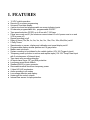
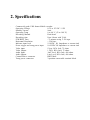
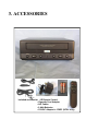
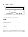
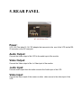
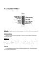
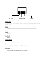
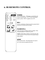
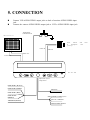
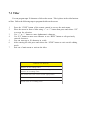
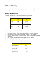
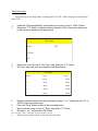
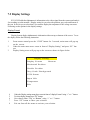
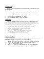
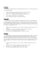
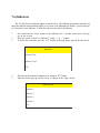
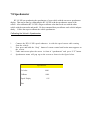
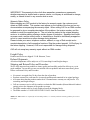
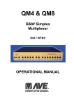
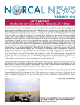
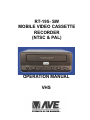
RT-195- SW MOBILE VIDEO CASSETTE RECORDER (NTSC & PAL) OPERATION MANUAL VHS CAUTION! RISK OF ELECTRICAL SHOCK! DO NOT OPEN! CAUTION! TO PREVENT ELECTRIC SHOCK, DO NOT REMOVE COVER. NO USER SERVICEABLE PARTS INSIDE. REFER SERVICING TO QUALIFIED PERSONNEL. WARNING: TO PREVENT FIRE OR ELECTRIC SHOCK, DO NOT EXPOSE THIS APPLIANCE TO RAIN OR MOISTURE! WARNING! THIS EQUIPMENT GENERATES, USES, AND CAN RADIATE RADIO FREQUENCY AND IF NOT INSTALLED AND USED IN ACCORDANCE WITH THE INSTRUCTIONS MANUAL, MAY CAUSE INTERFERENCE TO RADIO COMMUNICATIONS. IT HAS BEEN TESTED AND FOUND TO COMPLY WITH THE LIMITS FOR A CLASS A COMPUTING DEVICE PURSUANT TO SUBPART J OF PART 15 FCC RULES, WHICH ARE DESIGNED TO PROVIDE REASONABLE PROTECTION AGAINST SUCH INTERFERENCE WHEN OPERATED IN A COMMERCIAL ENVIRONMENT. OPERATION OF THIS EQUIPMENT IN A RESIDENTIAL AREA IS LIKELY TO CAUSE INTERFERENCE IN WHICH CASE THE USER AT HIS OWN EXPENSE WILL BE REQUIRED TO TAKE WHATEVER MEASURES MAY BE REQUIRED TO CORRECT THE INTERFERENCE. Copyright (c)1999 TransAmerican International, Inc. 1. FEATURES • ♦ • • • • • • • • • • • • • • • ♦ ♦ ♦ ♦ ♦ ♦ ♦ ♦ 12 VDC mobile operation Remote IR on screen programming Universal Time/date display. 4 active-level and text programmable on screen indicator inputs 20-character programmable title, programmable ON/OFF Tape speed selection (SP/EP) up to 8 hrs with T-160 tape Power save mode on/off (the maximum current draw is 9 mA if power save is on and VCR is power off) Repeat recording on/off Delay-off timer (15s,30s,1m, 2m, 3m, 4m, 5m, 10m, 15m, 30m,45m,60m) on/off 5 Daily Timers Speedometer on screen display and calibration and speed display on/off Programmable display window position and 10 gray scales. Master reset sub-menu System recording to be initiated by the vehicle ignition (10V-18V Trigger-In input) Temporary power up button to remove and replace tapes (10V-18V Temp-Power input with 5 minute power off internal timer) Tape insert auto recording detection All inputs have Surge, RF, and EMI protection. Low power record mode 400mA. Standard DB-25 (m) rear connector. Removable terminal block from temporary power. 2 Head HQ VHS mechanism. Audio recording in all modes Low voltage detection and display. Heater and fan control outputs. Internal Dew sensor for tape protection. 2. Specifications · · · · · · · · · · · · · · · · Commercial grade VHS format Mobile recorder Operating Voltage 8.5V to 15V DC / 15W Standby current 9mA Operating Temp 0 to 40 °C (32 to 108 °F) Recording Method Dual-head Recording time Upto 8 hours with T-160 FFW/REW Time < 5 minutes using T-120 tape. Horizontal Resolution > 250 lines Indicator input level 5-18VDC Hi Impedence or current sink Power trigger and temp power input 10-18VDC Hi Impedence or current sink Video input 1Vp-p, RCA Jack, 75 ohms Video Output: 1 Vp-p, RCA Jack, 75 ohms Audio Input: Line Level, RCA Jack, 600 ohms. Audio Output: Line Level, RCA Jack, 600 ohms. Control/Power connector DB25 Male Temp power connector 3-position removeable terminal block 3. ACCESSORIES Included accessories: IR Remote Control Cigarette Cord Adaptor A/V Cables 2 AAA Batteries 110VAC Adapter to 12VDC (NTSC Only) 4. FRONT PANEL VIDEO CASSETTE RECORD AVE STOP/ POWER EJECT REC/SPEED SENSOR REW PLAY F-FWD AUTO CASSETTE COMPARTMENT Insert the VHS cassette into this compartment to load the tape. POWER DONOT USE THIS BUTTON. VCR power is controlled by the internal microprosser. The VCR will automatically power up when 12VDC applied. Red light on the power button indicate that VCRs power is ON. STOP/EJECT To stop the tape or eject a stopped tape. Green light on this button indicate that cassette is in the VCR. REC/SPEED This button can also be used to start recording manually. A Dim Red light indicates that the VCR speed is on SP mode. Green light indicate that VCR is in LP/EP mode. Orange light indicate that the VCR is recording in LP/EP mode and a dark red light indicate that the VCR is recording in SP mode. See programming section to set the speed of VCR. SENSOR This sensor receives the infrared signal from the remote control. REWIND Use this button to rewind the tape in the stop mode or to perform a reverse picture search in the play mode. A green light indicate that the VCR is rewinding the tape. PLAY Use this button to start the play back mode. A green light on this button indicate that the VCR is in the Play back mode. FAST FORWARD Use this button to fast forward the tape from stop mode or to perform a forward picture search during play back. A green light on this button indicate that VCR is fast forwarding the cassette. AUTO REPEAT When the tape ends and auto repeat is on then the VCR automatically starts rewinding the tape and to starts replay. A red light on this button indicates that the AUTO REPEAT is ON. The tape will auto rewind and play again indefinitely while in this mode. 5. REAR PANEL RT-195-SW Rear View Power: VCR -322 Plus takes 12-14 V DC adaptor that connects to the rear of the VCR via the DB25 connector or the DC coax jack. Audio Output: Connect the Audio output of the VCR to the audio input of the monitor. Video Output: Connect the Video output of the to Video input of the monitor. Audio Input: Connect audio output from the audio source to the Audio input of the VCR. Video Input: Connect the video output of the camera or other video source to the video input of the VCR. Pinout for DB25 FEMALE RECORD LED OUT POWER LED OUT GROUND 12 VDC OUT GROUND 12 VDC SWITCHED GROUND 12 VDC SWITCHED GROUND 12 VDC NOT CONNECTED FAN OUT NOT CONNECTED GND SPEED OOMETER IN 12 VDC OUT INDICATOR 4 INDICATOR 3 INDICATOR 2 TRIGGER IN INSTANT TRIGGER INDICATOR 1 TEMP POWER IN HEATER OUT NOT CONNECTED Heater Out Heater Out output become low when the temprature of the RT-195-SW becomes less than 40F. Temperory Power In Temperory Power In is an active high input. It can power up the VCR for 5 minutes upon receving a input pulse. Indicator 1-4 Indicator 1- 4 can be set as active high or active low inputs. You can label those input in the programming mode. Factory default setting is Indicator 1 is LT (leftsignal), indicator 2 is BRK (break), indicator3 is STP (STOP), and indicator 4 is RT(right signal). Upon reciving a active high input RT-195-SW will display that label on monitor. See section 7.6 for more details. Trigger IN It is recommended to connect Trigger In with the car ignition switch. That will turn on the VCR every time you start your car. 12 VDC TEMPWR GND Instant Trigger Instant trigger is an active high input. Upon receving the input pulse RT-195-SW turn on in the recording mode. Fan Out When the internal temprature of the VCR goes up to 90 F then fan output is goes to 0 V. 12 VDC Input 12 V. 12 VDC Out Output 12 V. 12 VDC Switched Can be used either input or output. Power Led Out Power LED output will be high when the VCR is power ON. REC Led Out Record Led output will be high when the VCR is recording. 6. IR REMOTE CONTROL REC POWER Dont use this button. VCR power is controlled by the internal microprocessor. The VCR will automatically power up when 12VDC is applied to the VCR. PAUSE/STILL SP/EP REC: PLAY REW _ POWER: Use the combination of these two buttons pressed simultaneously to manually start recording. F.F TRACKING + PAUSE/STILL Press during the recording to pause recording. Press during the playback to freeze the picture. Caution: If this button is held for 6 seconds then it will master reset the VCR and clear all the programming to factory default. SP/EP Dont use this button. Recording speed can only be set in the onscreen programming mode. STOP Press this button to stop a running tape. Alternatively press and hold that button for 3 to 5 seconds to access in the programming mode. PLAY Press this button to start the play back mode. REW To rewind the tape during the stop mode and to reverse picture search in play back mode. FAST FORWARD To fast forward the tape during the stop mode and forward picture search in the play back mode. In programming mode use this button to access the menu selection. TRACKING Use (+) or (-) button to manually adjust the tracking of the picture. In the programming mode use these buttons to move the cursor upward and downward. 5. CONNECTION n n Connect VCR AUDIO/VIDEO output jacks to back of monitor AUDIO/VIDEO input jack. Connect the camera AUDIO/VIDEO output jack to VCRs AUDIO/VIDEO input jack. TEMPORARY POWERSWITCH videomonitor 1234567890123456789012345 1234567890123456789012345 1234567890123456789012345 1234567890123456789012345 1234567890123456789012345 1234567890123456789012345 1234567890123456789012345 1234567890123456789012345 1234567890123456789012345 1234567890123456789012345 1234567890123456789012345 1234567890123456789012345 1234567890123456789012345 1234567890123456789012345 1234567890123456789012345 1234567890123456789012345 1234567890123456789012345 1234567890123456789012345 Video Camera in microphone preamp. AUDIO IN VIDEO IN VIDEO OUT AUDIO OUT RT-195-SW Optional Bus System wiring Harness INDICATOR 1 (BLACK) INDICATOR 2 (GREEN) (RED) POS INDICATOR 3 (RED) (BLACK) NEG INDICATOR 4 (BROWN) TRIGGER IN (WHITE) (RED) POWER TO SPEED (12V) (BLACK) COMMON (WHITE) SPEED SIGNAL with with built 8. BASIC OPERATION Insert Cassette: n Power up the VCR. n Insert the tape in to the cassette compartment until VCR pulls cassette in. WARNING : Do not force the tape in the mechanism or this will demage the VCR. If 12 VDC is not applied to the VCR it will not accept the tape. Start Recording n Press and release the REC/SPEED button on the front panel or on the IR Remote Stop Recording n Press the Stop/ Eject button from the front panel or the Stop button of the IR Remote control to stop recording. Playback n Press and release the Play button either from the front panel or from the IR Remote control. Ejecting the Tape n Press the Stop/ Eject button once to stop the tape then press and Stop/Eject button again to eject the tape. 7. PROGRAMMING Time / D a t e 1:11:37P T/D Display ON Time Format 12 Hour Date Format MM/DD/YY Set Time/Date Reset Time/Date Exit 1/01/98TH Recording Setting Record Rept ON Set Delay- off 1 min Delay- off ON Daily Timers Tape Speed RT- 195SW SP Exit Daily Timers Timers O FF Set Timer Exit Main Menu Display Setting Set Time/Date Display Format Titler Bottom Horizontal Position Record Setting Set Timer Verticle Position Display Setting Gray Scale/ Background Indicator VC R Status Power Saver Timer Start Stop 1 00:00 00:00 Speedometer Input Volt Master Reset Temprature 2 00:00 00:00 Exit Exit 3 00:00 00:00 4 00:00 00:00 5 00:00 00:00 Indicator Text Indicator 1 Indicators Indicator 2 Indicator 3 Indicator Text Indicator 4 Effective Level Exit Exit Master Reset Speedometer Cal value 0000 Calibrate 0000 Speed Display Exit ON Back To the Main Menu Do Master Reset Indicators Indicator 1 Active High Indicator 2 Active High Indicator 3 Active High Indicator 4 Active High Exit 7.1 Accessing Main Menu Things to K now "STO P" Press and hold remote control's "STO P" button for 5 seconds to access the main menu. "F.F" Press this button to enter or exit any selection. "+" Prsss this button to move cursor up. "- " Press this button to move cursor down. To access the on screen programming press the STOP button of the remote control for about 6 seconds. Following programming menu will be appear on the screen of monitor or LCD. Main Menu Set Time/Date Titler Record Setting Display Setting Indicator Power Saver Speedometer Master Reset Exit 7.2 Time & Date Setup An Internal clock generates time and date that super impose on the monitor screen. After the clock is set, the date and time modes are displayed on the monitor screen (live picture). Display Time & Date on Screen 1 2 3 4 5 Under Display Time & Date menu place the cursor in front of T/D display and press F.F button of the remote control. Press + or - button to select ON or OFF. Press the F.F button again to select your selection. To exit out of Display Time & Date, place cursor in front of Exit and press F.F button. Exit out of all the menus to activates above selection. Note: Selecting OFF will turn off Time & Date display. Time / D a t e T/D Display ON Time Format 12 Hour Date Format MM/DD/YY Set Time/Date Reset Time/Date Exit Selecting Time Format 1 2 3 4 5 Place the cursor in front of Time Format and press and release the F.F button. Cursor will start blinking. Now push + or - button to select 12 or 24 time display mode. After selecting the desired selection press and release the F.F button. Exit out from all menus to activate your selection. Selecting Date Format 1 Under the Time & Date menu place the cursor in front of Date Format and press remote controls F.F 2 3 4 button. Cursor will start blinking. Chose the format from the selection yy/mm/dd or mm/dd/yy or dd/mm/yy by pressing either + or - button. Exit out from all the menus to activate your selection. Set Time & Date 1 Under the Time & Date menu, place the cursor in front of Set Time/Date and press F.F button. 2 Time and Date window pop on the screen as shown in the figure below. 1:11:37P 3 4 5 6 1/01/98TH By pressing + or - button you can change the blinking digit of Time or Date. Press REW and F.F button to move blinking digit either left or right side. After setting the Time and/or Date press STOP button. Exit out all the menus to activate the time that had been enter. Reset Time & Date 1 3 4 5 Under the Time & Date menu select Reset Time/Date. Press and release F.F button. It will reset the time and date to factory default. Exit out from all the menus to activate the above selection. 7.3 Titler You can program upto 20 character of title on the screen. Title is places in the video horizontal line. Follow the follwoing steps to program the title on the screen. 1 2 3 4 5 6 7 Press the STOP button of the remote control to access the main menu. Place the cursor in front of titler using + or - button then press and release F.F to accept the selection. Use + or - button to enter alphanumeric character. Use F.F button to enter next character or use REW button to edit previously entered character. You can enter up to 20 character in a title. After entering the title press and release the STOP button to exit out title editing mode. Exit out of main menu to activate the titler. THIN GS TO K N O W "- " button moves the alphabet in ascending order and numerics in descending orider. "+" button moves the alphbets in descending order and numerics in ascending order. "F.F" button move the cursor toward right position. ":REW" back space. "STO P" Exit out of editing mode 7.4 Record Setting Before performing the play back/recording, it is necessary to set the desired tape speed. You can set the tape speed, repeat record, daiiy timer, delay-off from the record setting menu. Record Speed Selection Consult the following table to select a correct speed for your purpose TAPE TYPE SP EP T- 160 3HRS 9 HRS T- 120 2HRS 6 HRS T- 90 1HR 30 MIN 4 HRS 30 MIN T- 60 1 HR 3 HRS T- 30 30 MIN 90 MIN Follow the steps to set the speed in the VCR. 1 2 3 4 5 6 7 Press remote controls STOP button for 5 seconds to access the main menu. Place the cursor in front of Recording Setting by using + or - buttons. Press F.F button to accept selection, Recording setting will pop up as shown in the figure below. Now place the cursor in front of Tape/Speed and press F.F button. Select EP or SP by pressing the + or - button. Press the F.F button after selecting the recording speed. Exit from all the menus to activate your selection. Recording Setting Record Rept ON Set Delay- off 1 min Delay- off ON Daily Timers Tape Speed Exit SP Repeat Recording Follow these steps below to enable auto rewind and auto recording feature of the VCR. This exclusive feature of the VCR keep contineous recording by automatically rewinding the Video cassette without any manual interaction. 1 2 3 4 Under the recording setting menu place your cursor in front of Repeat Rec and press the F.F button. Select ON to enable the option or OFF to disable it by using + or - button. Press F.F button after making your selection. Exit out of all the menus to activate your choice. Recording After Ignition OFF RT-195-SW give an additional option of recording even if the ignition of the vehicle is off. It can also let you specify the recording time in minutes that you want to record after the ingition turned off. Follow the steps to turning ON or OFF the Delay off feature of the RT-195-SW. Turning off the Recording with Ignition power off 1 2 3 4 Under Recording Setting menu place cursor in front of Delay-Off. To select Delay-off press the F.F button. By using + or - button select OFF. Now exit out from all the menus to activate your selection. Turning on the Recording with Ignition power off & setting Recording Time 1 Under Recording Setting menu place cursor in front of Delay-Off. 2 To select Delay-Off press the F.F button. 3 By using + or - button select ON and press F.F button. 4 Now place the cursor in front of Set Delay-off and press F.F button. 5 Now using + or - key select the desire time you want VCR to operate after ignition turn off. 6 Press F.F button after making your selection. 7 Exit out of all the menus to activate your selection. Timer Recording You can set up to five daily timer recording in RT-195 SW. Follow the steps to set the alarm in the VCR. 1 2 Under the Recording Setting menu place your cursor in front of Daily Timers , Now press F.F button to select the above selection, Daily Timer menu will pop up on the screen as shown in the figure below. Daily Alarm Timers O FF Set Timer Exit 3 4 Now move cursor in front of Set Timer and press the F.F button. Set Timer menu will pop up as shown in the figure below. Set Timer 5 Timer Start Stop 1 00:00 00:00 2 00:00 00:00 3 00:00 00:00 4 00:00 00:00 5 00:00 00:00 6 7 8 Enter the start and stop time for the recording. by using + or - button and use F.F or REW to next or previous entry. Press the Stop button to after all the recording timers. Now move the cursor in front of Timer and press F.F button. By using + or - button select ON button. 9 Exit out from all the menu to activate the selection. Note: Selecting OFF will disable all the Alarm timer entered. 7.5 Display Settings RT-195 SW adds the alphanumeric information to the video signal from the camera and sends it for recording or to the monitor. Display setting let you select the position, gray scale and format of the text It also let you to select that if you want to display the temprature or the voltage on screen. Following are the options in the display settings. Display Format Display format display alphanumeric information either on top or bottom of the screen. To set the display follow the following instruction. 1 From remote control press the STOP button for 5 seconds, main menu will pop up on the screen. Under the main menu move cursor in front of Display Setting and press F.F button. Display Setting menu will pop up on the screen as shown in figure below. 2 3 Display Setting Display Format Bottom Horizontal Position Verticle Position Gray Scale/ Background VC R Status Input Volt Temprature Exit 4 5 6 7 8 Under the Display setting menu place cursor in front of display Format using + or - button. To select display format press F.F button. Now choose either Top or Bottom using + or - button. Press F.F button to chose your selection. Exit out from all the menus to activate your selection. Horizontal Position Horizontal position set the alphanumeric text position horizontally. Follow the steps to set the Horizontal position. 1 2 3 4 5 6 Under the display setting menu place your cursor in front of Horizontal Position. Press the F.F button to select the horizontal position. A small box will pop up on the screen. Press + or - button to select the appropriate position. After selecting the position press the F.F button Exit out from all the menus to activate your selection. Vertical Position Vertical position set the alphanumeric text position vertically. If Display Format is set on TOP then vertical position let you chose the position from top of the screen to middle of the screen. If display format is set to bottom then vertical position can be choose from middle of the screen to the bottom of the screen. Follow the steps to set the vertical position. 1 2 3 4 5 6 Under the Display setting place the cursor in front of vertical position. Press the F.F button to make vertical position a selection. A small box will pop up on the screen. Press + or - button to select the appropriate vertical position. After selecting the vertical position press the F.F button. Exit out from all the menus to activate your selection. Gray Scale / Background Gray Scale/ Background color set the gray scale and back ground color of the alphanumeric text on the display. Follow the procedure to set gray scale or background color. 1 2 3 4 5 6 Under the Display setting place the cursor in front of gray scale/ back ground color.. Press the F.F button to make gray scale/ Background color a selection. A small box will pop up on the screen. Press + or - button to select the appropriate gray scale or back ground color. After selecting the gray scale or back ground color press the F.F button. Exit out from all the menus to activate your selection. VCR Status VCR Status if on displays all the VCR operating modes on the screen. Follow the procedure to turn VCR Status On/Off. 1 2 3 4 5 Under the Display setting place the cursor in front of VCR Status. Press the F.F button to make VCR Status a selection. Press + or - button to turn VCR Status either ON or OFF. After making selection press F.F button again. Exit out from all the menus to activate the selection. Input Voltage RT-195- SW has an option to display the input voltage on the screen. You can turn off or on the voltage display from the display settings. A LOW VOLTAGE message will be start flashing on the screen if the input voltage is less than 9V. If the voltage is less than 9 V and cassette is out then CASS OUT message will be start flashing but VCR will not accept the tape. Follow the steps to turning the voltage display on or off. 1 2 3 4 Under the main menu place the cursor in front of Display Setting and press the F.F button. Now place the cursor in front of Input Voltage and press F.F button. Press the + or - button to select ON or OFF. Exit out from the programming mode to activate the selection. Temprature A built in temprature sensor keep tract of the internal temprature of RT-195-SW. You can view the internal temprature by enabling the temprature display under the display setting menu. If the temprature goes higher than 90 F then the Fan Out put is activated (active low). If the temprature goes lower than 40 F then the Heater output is activated (active low). If temprature goes less than 32 F then the temprature will be turned off. Follow the steps to enable to temprature display on the screen. 1 2 3 4 Under the main menu place the cursor in front of Display settings and press F.F button. Place the cursor in front of Temprature and press the F.F button. Press the + or - button to select ON or OFF button. Exit from the programming mode to activate the selection. 7.6 Indicators RT-195 SW has four indicator inputs as shown below. The Indicator programing menu let you name the indicator input and then display it on screen as an alphanumeric format. you can enter up to 3 character for any indicator. Follow the steps to name any or all indicator. 1 2 3 Press and hold the Stop button of the indicator for 5 seconds, main menu will pop up on the screen. Place the cursor in front of Indicator using + or - button. To make this selection press the F.F button, following figure pop up on the screen. Indicators Indicator Text Effective Level Exit 4 5 Place the cursor in front of Indicator text and press F.F button. Indicator menu pop up on the screen as shown in the figure below. Indicator Text Indicator 1 Indicator 2 Indicator 3 Indicator 4 Exit 6 7 8 9 10 11 12 13 14 Place cursor in front of indicator you want to name. (e.g. if you connect to indicator 3 to breaks and want to name is as BRK) Press the F.F button to accept the selection. Enter the name you want to enter by using + , -, REW or F.F buttons. After entering title press the Stop button to exit out to Indicator text menu. Now select other indicator to name another input indicator or select Exit to exit out of indicator text menu. Under the Indicator place the cursor in front of Effective Level. Press F.F button to accept the above selection. Under Effective level chose either active high or active lowdepending upon the input signal. Exit out from all the menu to activate the above changes 7.7 Power Save If the VCR is idle for more than 5 minutes and power Save option is ON then VCR is automatically shut down. Follow the instructions to activate that option. 1 2 3 4 5 Press and hold the remote control STOP button for 5 seconds, main menu will pop on the screen. Place the cursor in front of Power Saver and press the F.F button. Now use +or - button to select either ON or OFF. After making your selection press the F.F button. Exit out from the menu to activate your selection. 7.8 Speedometer RT-195 SW can synchronize the speedometer of your vehicle with the on screen speedometer display. That can be done by calibarating the RT-195-SW with the speedometer sensor of the vehicle. After calibration RT-195 SW assigns a calibrate value that can be use with the other vehicle with the same make and model. We do recommend that you calibrate wach vehicle independently. Follow the steps to calibrate the vehicle speedometer. Calibrating the Vehicles Speedometer 1 2 3 4 Connect the RT-195 SW speed odometer in with the speed sensor cable coming from the vehicle Now press and hold the Stop button of remote control until main menu appears on the screen. Under main menu place the cursor in front of speedometer and press F.F button Speedometer menu will pop up on the screen as shown in the figure below. Speedometer Cal value 0000 Calibrate 0000 Speed Display Exit ON 5 6 7 8 9 Now place cursor in front of Calibrate and press F.F button. A message will pop up on the screen stating Calibration in Progress. Press Stop button to Finish. Now drive the vehicle for about a mile. RT-195 SW will calibrate the speedometer and assign a Calibrate value to that vehicle. Exit out from all the menus, RT-195 SW virtual speedometer has been calibrated. Using the Calibrate Value to Calibrate Speedometer Note: To enter the cal- Value, all the vehicle must have same make and model . 1 2 3 4 5 Under the speedometer menu place the cursor in front of Calibrate using + or - buttons. Press the F.F buttons to accept the above selection. Enter the cal value obtain previously by using the +, -, REW or F.F buttons. After entering the cal value press stop button. Exit out of all the menus to activate above selection. Display Speed on the Monitor 1 2 3 4 5 Under the speedometer menu place cursor in front of Speed display using + or - button. Press F.F button to accept the selection. Using + or - button use ON to display vehicle speed on monitor. Press the F.F button again to accept the selection. Exit out from all the menus to activate the selection. 7.9 Master Reset Master reset, resets all the programming to factory default. Follow the steps to do a master reset on RT-195 SW. 1 2 3 4 5 6 Under the main menu place the cursor in front of Master Reset. Press F.F button to accept that selection. Master reset menu will pop up on the screen as shown the figure below. Using the + or - buttons to place cursor in front of Do Master Reset Press the F.F button to master reset the RT-195 SW. AVE Copy right menu will pop up on the screen notifying that VCR has been master Rested. 8. TROUBLESHOOTING No Power in the VCR Check the wiring to the battery. The Red wire of the RT-195 SW should be connected to the positive terminal through a 3A fuse. The black wire should connect with negative terminal of the battery. Check the fuse. If the fuse blown, find out why the fuse blew and then replace it. Make sure the white wire connect to the ignition and ignition switch is on. If the VCR powers up when the temporary switch is pressed, the ignition switch connection may be faulty. Start the engine to make sure the battery voltage is high enough to power up the VCR. No Picture on the monitor Check the Video camera and monitor connection with the VCR. If the camera equipped with the power indicator make sure the indicator is on. Start the engine to make sure the battery voltage is high enough to power the VCR. No Picture or fuzzy but audio is clear The head may require cleaning. Use a cleaning tape to clean VCR head. Replace all the worn or dirty tapes. VCR will not Record Make sure that video tape is not write procteted. Start the engine to make sure the battery voltage is high enough to power the VCR. Power light is blinking The VCR has detected a faulty or jammed tape. Try to unjam the tape and remove it from VCR. Be careful not to demage the VCR. Do not poke screw drivers or other tools into the VCR. AVES LIMITED EQUIPMENT WARRANTY FOR RT-195-SW PLUS. AVEs Products are guaranteed to be free of defects in workmanship and material. If any failure, resulting from either workmanship or material defects should occur under normal and proper usage within the period stated below for each product form the original provable date of purchase, such failure should be repaired at no cost to the buyer for labor and if the defective product(s) is sent to AVE. RT-195-SW: One (1) year electrical parts, ninety (90) days mechanical parts, ninety (90) days labor, ninety (90) days on video heads. This AVE warranty does not cover the following: Products received for repair without an RMA number, sales or delivery receipt showing date of purchase by original customer. Damages caused by incorrect use, carelessness, unauthorized alterations, improper Storage or unauthorized service installation or repairs. Damage caused by fire, flood, lighting, vandalism, collision, act of God, or other events beyond the control of AVE. External parts such as cabinet and key pad. Damages resulting from loss of use, loss of time or inconvenience, cost of temporary replacement units or spares, property damage caused by this unit or its failure to work, or any other incidental or consequential damages. Hostile operating environments. In transit damage claims, improper handling by carrier of post offices. Products or parts thereof which have had serial numbers removed, altered or defaced. Damage defect or failure caused by or resulting from the operation of the unit by incorrect voltages. The use of components that do not meet AVE specifications. Periodic maintenance and adjustments resulting from normal use such as video head cleaning, mechanical part ware, etc. Damage resulting from use of cleaning cassettes. IMPORTANT: This warranty is in lieu of all other warranties, guarantees or agreements whether expressed or implied and no person, dealer, or company is authorized to change, modify, or extend its term in any manner what so ever. Warranty Return Policy Before sending any AVE product to the factory for warranty repair, the customer must obtain an RMA number. This number must appear on the outside of the box and on any documentation accompanying the warranty repair. When calling AVE for an RMA number, be prepared to give a complete description of the problem, the invoice number, and the address to return the repaired item to. The unit must be packed in the original shipping carton or in suitable packing offering a similar degree of protection. Separate items such as power cords, remote controls units, or transformers, should be individually wrapped so as not to cause scratches or other damage during shipment. Please include your name, telephone number, address, a copy of Sale receipt and a complete description of all inoperative functions. Ship the product prepaid. AVE will pay for the return shipping. However, AVE is not responsible for damage during shipment. AVE will not accept any warranty repair without an RMA number. Freight Policy Products and Prices are shipped F.O.B. Houston, Texas. Refused Shipments All refused shipments will be subject to a 15% restocking fee and freight charges. Shipping and Return Policy and Procedure We are fully inspected our products to insure quality and carefully packed for delivery to you in good condition. In case that you are not satisfied with our products and must return them, please follow our Return Policy and Procedure. • • • • • • No return is accepted after 30 days from the date of purchase. Products returned for credit must be in unused condition and contained in its orignal package. All return other than the products under the AVE manufacture warranty are subjected to 15% restocking and freight charges. Call our customer service toll free number to obtain the RMA number (Return Material Authorization) prior to the shipment of the product to return. The RMA number must be clearly displayed on all the shipping labels. The RMA number is VALID ONLY FOR 15 DAYS from the issued date. NOTE: The RMA number is required for all returned products, i.e. warranty and non-warranty products for services and repair.