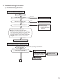
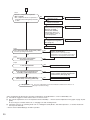
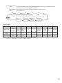
1
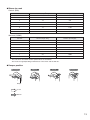
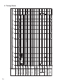
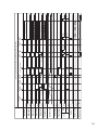
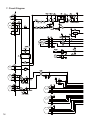
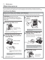
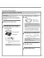
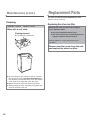
ADVANCED AND EVER ADVANCING 2010 DEHUMIDIFIER SERVICE MANUAL Model MITSUBISHI ELECTRIC No.MJW-10010 MJ-E15BX-S1-IT Sold from 2010 CONTENTS 1. 2. 3. 4. 5. 6. 7. 8. 9. 10. 11. 12. 13. 14. Product specifications ···································································································2 Outer Dimensions ··········································································································3 Names and Functions of Parts ······················································································3 Wiring Diagram ···············································································································5 1) Wiring Diagram ········································································································5 2) Board Diagram ·········································································································5 Function ··························································································································6 Timing Charts ················································································································14 Circuit Diagram ··············································································································16 Technical points ············································································································18 Troubleshooting Procedure ··························································································19 1) Troubleshooting flowchart ·······················································································19 2) Key Component Check Procedures ········································································21 3) Error Indications and Corrective Actions ·································································22 4) Self diagnostic test program ····················································································22 Troubleshooting ············································································································24 Maintenance···················································································································26 Disassembly and Reassembly Hints ···········································································30 Parts Catalog ·················································································································34 Precautions ····················································································································46 1. Product specifications Mode MJ-E15BX-S1-IT Electrical characteristics Performance Item Dehumidifying capacity 15.0 (30°C room temperature, 80% relative humidity) (liters/day) Operating noise High 49 levels(dB) Low 39 Power supply (phases,V,Hz) Single phase, 220-240V, 50Hz Power consumption (W) 290 Operating current (A) 1.4 Starting current (A) 5.5 Color tone Mocha Dimensions (H×W×D mm) Weight (kg) 14 Coolant quantity (g) 160 Slit fin Condenser Slit fin Compressor protection Thermal overcurrent relay Model XB460VTE Output (W) 150 Winding resistance (Ω)(20˚C) Primary: 26.1, subsidiary: 70.7 Blower protection With temperature fuse Type Blower Product performance Compressor Evaporator Sirocco fan Output (W) Cool air motor: 10 W, Warm air motor: 20 W Cool air Cool air Warm air Warm air Speed (rpm) AUT0 Flow rate (m3/min) Operating room temperature (reference) (˚C) Defrosting method 980 1100 LOW 780 4.0 738 LAUNDRY (HIGH) 2.6 Warm air 1200 1100 4.3 Hot gas type Built-in humidity sensor Tank full protection Lead switch (automatic) Tank capacity (liters) Auto-stopper tripped with about 2.5 liters of water Continuous drainage Commercial hose (inside diameter 15 mm) Timer Cool air 1 ~ 35 (˚C) Humidity control Operation modes 2 568×390×205 DEHUMIDIFYING (AUTO•HIGH•LOW), LAUNDRY (HEAVY•NORMAL•HIGH), SPOT AIR (WARM AIR•COOL AIR/VARY•COOL AIR/LOW), DEO-DRY, DRYING INSIDE Off timer (2•4•8h) Air cleaning performance Yes Plug socket rating 16A The operating noise levels indicated are typical values measured in our anechoic room. 142.5 568 205 2. Outer Dimensions 20.5 390 205 3. Names and Functions of Parts Control Panel z CHILD LOCK lamp Lights while child lock is active. z CHILD LOCK Switch To lock/unlock the switch, press the switch for at least 3 seconds. z Tank FULL lamp The lights up to warn that the water tank is full. z DEFROST lamp Lights during defrosting operation. z DRYING INSIDE lamp z Flashes during the drying inside operation. z Lights when the drying inside operation is waiting to begin. z DRYING INSIDE switch Use this to switch the internal drying operation ON and OFF. z OFF TIMER lamps The lamp for the remaining time lights when the OFF timer is operating. z OFF TIMER Switch Use this to set the OFF timer operation time. z Operation Mode lamps The lamp for the current operating mode lights. z SPOT AIR Switch Switches to cold wind operation. z DEO-DRY lamp Lights during deodorizing clothes operation. z DEO-DRY Switch Switches to deodorizing clothes operation. z Operation Mode lamps The lamp for the current operating mode lights. z DEHUMIDIFYING Switch Switches to dehumidifying operation. z Operation Mode lamps The lamp for the current operating mode lights. z LAUNDRY Switch Switches to laundry operation. z SWING LOUVRE lamps The lamp for the swing direction of the louvre lights. z SWING LOUVRE Switch Sets the swing louvre direction or locks it into position. z CURRENT HUMIDITY Indicator This indicates the approximate current humidity (The current humidity is displayed in a range from 30 to 80%). z POWER ON/OFF Switch Use this to turn the power ON and OFF. 3 Front Back Air intake Control panel Main air outlet Handle Louvre Filter cover Back air outlet Sensor Do not cover. Silver ion sterilizing and deodorizing filter Power plug Accessory Wheel (4) z Silver ion sterilizing and deodorizing filter Tank Hereafter referred to as simply “sliver ion filter.” Tank lid The silver ion filter is supplied with the unit at the time of purchase. Set before using the unit. Tank guard What is a silver ion sterilizing and deodorizing filter? The silver ion sterilizing and deodorizing filter is a filter consisting of fibres containing special deodorant and silver ion anti-bacterial agent (anti-allergen, anti-virus, and sterilization). Tank handle Cigarette smoke and toxins found in smoke, such as carbon monoxide, cannot be removed with this filter. Level window Continuous drainage lid Installing your dehumidifier Make sure to leave some space around the unit. At least 50 cm At least 20 cm At least 20 cm At least 20 cm At least 20 cm <Operating noise> Use the unit on a mat or the like. This reduces vibration and noise. It also prevents leaving depressions on carpets, etc. 4 Floating element The water tank may contain water residue at time of purchase. This is from final product testing at the factory and is not due to a defect. It is impossible to remove the back panel because the two spots shown are fastened with two special screws. If the supply cord is damaged, it must be replaced by the manufacturer, its service agent in order to avoid a hazard. 4. Wiring Diagram 1) Wiring Diagram Tube temperature thermistor Power plug Run capacitor Solenoid valve P3 P6 Compressor P1 P2 P15 Floating element SW P12 P11 Cool air damper Power/control board P7 P8 Warm air motor Cool air motor P31 TH P20 P21 P32 HUM.S P100 P9 P10 Stepping motor Warm air damper P101 Board-in connector Operation control board 2) Board Diagram [Operation control board] [Power/control board] 5 5. Function Function List Cool air (Low or Vary) Warm air (Condensation prevention) DEO-DRY Drying inside Tank full detection Defrosting OFF ON ON ON ON ON — OFF ON — Cool air fan OFF ON ON ON ON ON — OFF OFF — Warm air fan OFF ON ON ON ON ON — OFF OFF — Solenoid valve OFF OFF OFF OFF OFF OFF — OFF ON — Swing louvre Closed U U U U U Upward OFF OFF Damper Fully closed — Dehumidifying — Dehumidifying — — — ☆ — ☆ — ☆ — ☆ — Laundry ☆ ☆ LED indicator Dehumidifying Warm air DEO-DRY Tank full — Drying inside — Defrost — Current Humidity Indicator — Power Laundry Dehumidifying Switch ☆ Spot Air Swing Louvre Spot Air DEO-DRY Swing Louvre Off timer Drying inside Child lock : Lit/Operable : Flashing : Off/Stopped/Inoperable U: Lit only when swing on ☆: LED lights at each operation mode —: Varies by conditions 6 Cool air Warm air Child lock Dehumidifying (Low, High or Auto) Compressor Operation off Laundry (High, Normal or Heavy) Operation mode U U U U U — Laundry Operation 1. HIGH ① Control Summary (a) Dehumidifying operates continuously regardless of the humidity. (b) The constant compressor, cool air and warm air fans operate continuously. Target part Compressor Cool air fan Warm air fan Solenoid valve Louvre Damper Operation ON Rank control Rank control OFF Operation mode Dehumidifying position ② Laundry operations are disabled in the following cases. (a) When the LAUNDRY switch is pressed, it switches to LAUNDRY (NORMAL) operation. (b) When the DEHUMIDIFYING switch is pressed, it switches to the previously set DEHUMIDIFYING operation mode (DEHUMIDIFYING LOW, DEHUMIDIFYING HIGH or AUTO). (c) When the SPOT AIR switch is pressed, it switches to the previously set SPOT AIR operation mode (COOL AIR LOW, COOL AIR VARY or WARM AIR). (d) When the DEO-DRY switch is pressed, it switches to the DEO-DRY mode operation. 2. NORMAL or HEAVY z NORMAL Operating time From operation start to 30 minutes Fan temperature table 0 1 2 3 Damper position Rank5 Dehumidifying Rank7 Rank7 Rank7 Rank5 Dehumidifying Rank7 Rank5 Dehumidifying Rank6 Rank7 Rank7 Rank5 Dehumidifying Rank7 Rank7 Rank5 Dehumidifying Rank6 Rank4 Rank4 Rank5 Warm air Rank6 Rank6 Rank5 Dehumidifying Rank6 Rank6 Rank6 Rank5 Dehumidifying Rank6 Rank6 Rank5 Dehumidifying Rank6 Rank6 Rank6 Rank5 Dehumidifying Rank6 Rank6 Rank5 Dehumidifying Rank4 Rank4 Rank4 Rank5 Warm air 1 2 70%~80% Rank7 Cool Average 60%~69% Rank6 air fan humidity 30%~59% Rank6 Rank7 Rank7 Rank7 70%~80% Rank6 Warm Average 60%~69% Rank6 air fan humidity 30%~59% Rank6 3 Damper position After 30 minutes or more 0 z HEAVY Operating time From operation start to 30 minutes After 30 minutes or more 1 2 3 Damper position 0 1 2 3 Damper position 70%~80% Rank7 Cool Average 60%~69% Rank6 air fan humidity 30%~59% Rank6 Rank7 Rank7 Rank5 Warm air Rank7 Rank7 Rank7 Rank5 Warm air Rank7 Rank7 Rank5 Warm air Rank6 Rank7 Rank7 Rank5 Warm air Rank7 Rank7 Rank5 Warm air Rank6 Rank4 Rank4 Rank5 Warm air 70%~80% Rank6 Warm Average 60%~69% Rank6 air fan humidity 30%~59% Rank6 Rank6 Rank6 Rank5 Warm air Rank6 Rank6 Rank6 Rank5 Warm air Rank6 Rank6 Rank5 Warm air Rank6 Rank6 Rank6 Rank5 Warm air Rank6 Rank6 Rank5 Warm air Rank4 Rank4 Rank4 Rank5 Warm air Fan temperature table 0 ①Control Summary (a) The dehumidifying time changes depending on the humidity, temperature and time. (b) The time when the humidity changes is measured, and dehumidifying operation is automatically stopped when the laundry is dry. (c) Normal Target part Compressor Cool air fan Warm air fan Solenoid valve Louvre Damper Operation ON Rank control Rank control OFF Operation mode Dehumidifying → Warm air *The damper switches when humidity drops below 60% (d) Heavy Target part Compressor Cool air fan Warm air fan Solenoid valve Louvre Damper Operation ON Rank control Rank control OFF Operation mode Warm air 7 ② Startup conditions (a) When operation is on while LAUNDRY operations are selected (b) When LAUNDRY operations are selected by operating the LAUNDRY switch ③ Stopping condition 1 (a) Average humidity and temperature are measured 30 minutes after starting LAUNDRY operations, and every 10 minutes from then on. (Average humidity and temperature updates are performed at the same time as humidity measurements. Once every 15 seconds) (b) A shows the average temperature when the average humidity is 50% or less. (0~39˚C) (c) B shows the time elapsed until the average humidity is 50% or less after starting LAUNDRY operations. (B 40) (d) After measuring A and B mentioned above, dehumidifying operations are then performed only for time Y calculated by the following equation. NORMAL Stop time Y = Elapsed time B × (1.4 - Temperature A /100) HEAVY Stop time Y = Elapsed time B × (1.5 - Temperature A /100) Example) The shortest stop time is as follows. (When the temperature = 30˚C) The shortest stop time Y = 40 × (1.4 - 30/100) = 44 minutes Therefore, the shortest time before stopping after starting LAUNDRY (NORMAL) operations is 84 minutes. ④ Stopping condition 2 (a) After starting LAUNDRY operations X Hours elapsed (Where X is the E2PROM data modification range of integers form 1 to 12 where 12 is the default) (b) Stopping condition 2 is applied in the following situations. - After starting LAUNDRY operations, when humidity does not reach 50% or less after X hours have elapsed - When B+Y X hours under stopping condition 1 ⑤ The time count during tank full detection is as follows. (a) Before detecting 50% or less for stopping condition 1 : Time count stop (b) After detecting 50% or less for stopping condition 1 : Time count continues (c) Stopping condition 2 : Time count stop <Stopping Condition> Time Y Humidity Normal/; Stop time Y = Elapsed time B (1.4 - Temperature A /100) Heavy; Stop time Y = Elapsed time B (1.5 - Temperature A /100) 50% ON Dehumidifying operation OFF 30 minutes 0 minutes 0 Y minutes B minutes 50% or less detected Operation stops Operation starts Room temperature A detected 40 Temperature ⑥ LAUNDRY operation mode is disabled in the following cases. (a) When the LAUNDRY switch is pressed, it switches to the following LAUNDRY operation mode. (b) When the DEHUMIDIFYING switch is pressed, it switches to the previously set DEHUMIDIFYING operation mode (Dehumidifying LOW, Dehumidifying HIGH or AUTO). (c) When the SPOT AIR switch is pressed, it switches to the previously set SPOT AIR operation mode (COOL AIR LOW, COOL AIR VARY or WARM AIR). (d) When the DEO-DRY switch is pressed, it switches to the DEO-DRY mode operation. 8 Dehumidifying operation 1. Automatic Operation 22˚Ct Temperature s20˚C 29˚Ct 36˚Ct s27˚C s34˚C Humidity table 0 1 2 3 Set humidity 60% 50% 60% 50% 60% 50% Dehumidification Dehumidifier mode Dehumidifier mode Circulate Dehumidifier mode Circulate Dehumidifier mode Cool air fan Humidity variation table 2 Warm air fan Rank3 Rank3 Rank3 Rank1 Rank1 To Dehumidifier mode Rank5 Cool air fan Humidity variation table 1 Warm air fan To Dehumidifier mode Cool air fan Humidity variation table 0 Warm air fan Rank0 (Stop) Rank0 (Stop) Rank3 Rank2 To Circulate mode Rank5 Rank5 To Circulate mode ① Control Summary (a) Adjusts humidity according to the room temperature for increased comfort. (b) When the temperature is high and the humidity is low, a circulator is activated that keeps the compressor off. Target part Compressor Cool air fan Warm air fan Solenoid valve Louvre Damper Operation ON/OFF Rank control Rank control OFF Operation mode Dehumidifying position (c) The temperature table is switched approximately once every 60 seconds. This prevents the blower fan from turning on and off at the 3-minute restart for the coloured section in the table above (51 to 59%). (d) When the room temperature is 29˚C or more (temperature rising) or 27˚C or more (temperature decreasing), the circulator operates when the humidity is below 50%. (e) When the humidity rises above 60% during circulator operation, dehumidifying begins again when the dehumidifier is set to operate at 50%, and circulator operations begin once humidity drops below 50%. Set humidity 60% Circulate Dehumidifier mode Circulate set humidity 60% set humidity 50% set humidity 60% Set humidity 50% 60% 50% Humidity Temperature ON Compressor OFF Blower ON OFF Humidity Set humidity 60% 60% When 60% exceeded, lowers to below 50% Set humidity 50% 50% Compressor OFF Fan rank 0 Compressor OFF Fan rank 0 20˚C 27˚C CIRCULATE mode Room temperature ② DEHUMIDIFYING AUTO operation mode is disabled in the following cases. (a) When the LAUNDRY switch is pressed, it switches to the previously set laundry operation mode (HIGH, NORMAL or HEAVY). (b) When the DEHUMIDIFYING switch is pressed, it switches to DEHUMIDIFYING LOW. (c) When the SPOT AIR switch is pressed, it switches to the previously set spot air operation mode (COOL AIR/ LOW, COOL AIR/VARY or WARM AIR). (d) When the DEO-DRY switch is pressed, it switches to the DEO-DRY mode operation. 9 2. Low Operation ① Control Summary (a) Dehumidifying operates continuously regardless of the humidity. (b) The constant compressor, cool air and warm air fans operate continuously. (c) By reducing the rank of the blower fan compared to high operation, the dehumidification function is decreased during operation.(Creating low noise) Target part Compressor Cool air fan Warm air fan Solenoid valve Louvre Damper Operation ON Rank control Rank control OFF Operation mode Dehumidifying position ② Low operation is disabled in the following cases. (a) When the LAUNDRY switch is pressed, it switches to the previously set LAUNDRY operation mode (HIGH, NORMAL or HEAVY). (b) When the DEHUMIDIFYING switch is pressed, it switches to DEHUMIDIFYING HIGH operation. (c) When the SPOT AIR switch is pressed, it switches to the previously set SPOT AIR operation mode (COOL AIR/LOW, COOL AIR/VARY or WARM AIR). (d) When the DEO-DRY switch is pressed, it switches to the DEO-DRY mode operation. 3. High Operation ① Control Summary (a) Dehumidifying operates continuously regardless of the humidity. (b) The constant compressor, cool air and warm air fans operate continuously. (c) By increasing the rank of the blower fan compared to low operation, the dehumidification function is increased during operation. Target part Compressor Cool air fan Warm air fan Solenoid valve Louvre Damper Operation ON Rank control Rank control OFF Operation mode Dehumidifying position ② High operation is disabled in the following cases. (a) When the LAUNDRY switch is pressed, it switches to the previously set LAUNDRY operation mode (HIGH, NORMAL or HEAVY). (b) When the DEHUMIDIFYING switch is pressed, it switches to dehumidifying auto operation. (c) When the SPOT AIR switch is pressed, it switches to the previously set SPOT AIR operation mode (COOL AIR/LOW, COOL AIR/VARY or WARM AIR). (d) When the DEO-DRY switch is pressed, it switches to the DEO-DRY mode operation. SPOT AIR 1. Condensation prevention operation ① Control Summary (a) Dehumidifying operates continuously regardless of the humidity. (b) The constant compressor, cool air and warm air fans operate continuously. (c) Perform warm air operation by placing the damper position in warm air mode. Target part Compressor Cool air fan Warm air fan Solenoid valve Louvre Damper Operation ON Rank control Rank control OFF Operation mode Warm Air Position ② Condensation prevention operation is disabled in the following cases. (a) When the LAUNDRY switch is pressed, it switches to the previously set LAUNDRY operation mode (HIGH, NORMAL or HEAVY). (b) When the DEHUMIDIFYING switch is pressed, it switches to the previously set DEHUMIDIFYING operation mode (DEHUMIDIFYING LOW, DEHUMIDIFYING HIGH or AUTO). (c) When the SPOT AIR switch is pressed, it switches to COOL AIR/LOW operation. (d) When the DEO-DRY switch is pressed, it switches to the DEO-DRY mode operation. 2. COOL AIR/LOW Operation ① Control Summary (a) Dehumidifying operates continuously regardless of the humidity. (b) The constant compressor, cool air and warm air fans operate continuously. (c) Perform cool air operation by placing the damper position in cool air mode. 10 Target part Compressor Cool air fan Warm air fan Solenoid valve Louvre Damper Operation ON Rank control Rank control OFF Operation mode Cool Air Position ② COOL AIR/LOW operation is disabled in the following cases. (a) When the LAUNDRY switch is pressed, it switches to the previously set LAUNDRY operation mode (HIGH, NORMAL or HEAVY). (b) When the DEHUMIDIFYING switch is pressed, it switches to the previously set DEHUMIDIFYING operation mode (DEHUMIDIFYING LOW, DEHUMIDIFYING HIGH or AUTO). (c) When the SPOT AIR switch is pressed, it switches to COOL AIR/VARY operation. (d) When the DEO-DRY switch is pressed, it switches to the DEO-DRY mode operation. 3. COOL AIR/VARY Operation ① Control Summary (a) Dehumidifying operates continuously regardless of the humidity. (b) The constant compressor, cool air and warm air fans operate continuously. (c) Perform cool air operation by placing the damper position in cool air mode. (d) Control fluctuations by changing the cool air fan rank level by time. ② Change the cool air/warm air fan rank as follows. ③ When the room temperature is 36˚C or more, the warm air fan rank is fixed at rank 5. Step Cool air fan Warm air fan Conditions for moving to next step Step1 Rank1 Rank4 Operation after 5 seconds Step2 Rank4 Rank4 Operation after 2 seconds Step3 Rank8 Rank4 Operation after 5 seconds ④ The step switching order is as follows. (a) Step 1 → 2 → 3 → 2 → 1 ... ⑤ COOL AIR/VARY operation is disabled in the following cases. (a) When the LAUNDRY switch is pressed, it switches to the previously set LAUNDRY operation mode (HIGH, NORMAL or HEAVY). (b) When the DEHUMIDIFYING switch is pressed, it switches to the previously set DEHUMIDIFYING operation mode (DEHUMIDIFYING LOW, DEHUMIDIFYING HIGH or AUTO). (c) When the SPOT AIR switch is pressed, it switches to WARM AIR operation. (d) When the DEO-DRY switch is pressed, it switches to the DEO-DRY mode operation. DEO-DRY mode operation ① Control Summary (a) Odors are removed by heating the clothes. (b) The following operations are performed during clothes deodorization. Target part Compressor Cool air fan Warm air fan Solenoid valve Louvre Damper Operation ON Rank control Rank control OFF Operation mode Cool Air → Warm air ② Startup conditions (a) When operation is on while DEO-DRY mode operation is selected (b) When DEO-DRY mode operation is selected by operating the DEO-DRY switch (c) When the DEO-DRY switch is pressed during clothes deodorization, DEO-DRY mode operation is restarted from the following step 1. ③ Operating Contents (a) Clothes equipment operates in order of the following steps. - Step 1 Cool air is blown through the clothes - Step 2 Warm air is blown through the clothes (b) Control panel operation during the above mentioned steps Step Cool air fan Warm air fan Compressor Solenoid valve Damper Conditions for moving to next step Step1 Rank4 Rank4 (Room temperature (Room temperature 35˚C or less) 35˚C or less) ON OFF Cool Air Operates for 20 min. Step2 Rank4 Rank4 (Room temperature (Room temperature 35˚C or less) 35˚C or less) ON OFF Warm air After 40 minutes operation, DEO-DRY mode operation ends ④ DEO-DRY mode operation stopping condition (a) Ends at the above mentioned step 2 (b) When the POWER switch is off ⑤ After DEO-DRY mode operation, it is disabled in the following cases. (a) When the LAUNDRY switch is pressed, it switches to the previously set LAUNDRY operation mode (HIGH, NORMAL or HEAVY). (b) When the DEHUMIDIFYING switch is pressed, it switches to the previously set DEHUMIDIFYING operation mode (DEHUMIDIFYING LOW, DEHUMIDIFYING HIGH or AUTO). (c) When the SPOT AIR switch is pressed, it switches to the previously set SPOT AIR operation mode (COOL AIR/LOW, COOL AIR/VARY or WARM AIR). (d) When the DEO-DRY switch is pressed, it restarts DEO-DRY mode operation from the first stage (step 1). 11 DRYING INSIDE operation ① Control Summary (a) Prevents the growth of mildew by drying the moisture accumulated on the heat exchanger when the dehumidifier is off. (b) DRYING INSIDE operation does not depend on a full water level to operate. (c) The following operations are performed during DRYING INSIDE operation. Target part Compressor Cool air fan Warm air fan Solenoid valve Louvre Damper Operation ON/OFF Rank control Rank control ON/OFF Stop at 90˚ Dehumidifying position ② DRYING INSIDE operation startup conditions (a) Automatic operation mode: When you turn on automatic drying inside operation by pressing the DRYING INSIDE switch during operation, DRYING INSIDE operation begins automatically when any of the following conditions are met. • When the POWER switch is not pressed • The Off timer is reached • When the DEO-DRY mode operation completes • When INTELLIGENT LAUNDRY operation completes (b) Manual operation mode: DRYING INSIDE operation begins when the DRYING INSIDE switch is pressed under the following conditions. • When operation is off. ③ Operating details (a) The following indications are displayed during DRYING INSIDE operation. • LED indicator: Only the drying inside LED flashes. The others are off. (b) DRYING INSIDE operates according to the following steps. • Step 1: Moisture is allowed to drip from the heat exchanger. The louvre is positioned upwards at 90°. • Step 2: Moisture on the heat exchanger is dried with air. • Step 3: Moisture on the heat exchanger is dried with heat. • Step 4: The heat exchanger is cooled if the temperature rises too high. • Step 5: Internal humidity remaining in Step 4 is discharged. After completion, the louvre moves to the closed position. (c) Step 3 is not performed when detecting a tube temperature that accompanies a microprocessor reset of 0˚C or less, or a room temperature of 0˚C or less, and jumps directly to Step 5. (d) Mechanisms operated in the above mentioned steps Step Cool air fan Warm air fan Compressor Solenoid valve Conditions for moving to next step Step1 Rank1 Rank1 OFF OFF 5 minute operations. Step2 Rank3 Rank0 (Stop) OFF OFF 25 minute operations. Step3 Rank0 (Stop) Rank0 (Stop) ON ON 45˚C or more detected in the tube temperature. Switches to step 5 for 20 minute operation Step4 Rank0 (Stop) Rank0 (Stop) OFF OFF Step 3 operating time is a total of 20 minute operations Step5 Rank1 Rank0 (Stop) OFF OFF After operating for 10 minutes, dry inside operation ends ④ DRYING INSIDE operation stopping conditions • Upon completion of Step 5 above • The following switches terminate the DRYING INSIDE operation when pressed. (a) The POWER switch (c) The DRYING INSIDE switch • The following operations are performed when DRYING INSIDE operation ends. (The louvre moves to the closed position) 12 Target part Compressor Cool air fan Warm air fan Solenoid valve Louvre Damper Operation OFF Rank0 (Stop) Rank0 (Stop) OFF CLOSE Fully closed position Blower fan rank Cool air (EVA) Fan rank Air Amount [m3/min] Rotation speed [rpm] 1 0.9 780 2 1.0 850 3 1.0 890 4 1.1 980 5 1.3 1,100 6 1.3 1,100 7 1.4 1,200 8 1.4 1,200 Fan rank Air Amount [m3/min] Rotation speed [rpm] 1 1.8 738 2 1.9 780 3 2.4 940 4 2.9 1,100 5 3.0 1,150 6 2.9 1,100 7 2.6 1,000 8 2.6 1,000 Warm air (COND) * The amount of air and the rotation speed values are standards. The values change depending on differences in the motor and the filter etc. Damper position Dehumidifying Warm air Cool air After blow/stop Damper Cool air Warm air 13 14 Swing ON Damper (Blowing route position) Drying inside lamp Buzzer Louvre Swing OFF Tank full lamp Float switch Tube temperature Solenoid valve Warm air fan Cool air fan Compressor Mode lamps Operation Max 3minutes Dehumidifying low Dehumidifying high CLOSE OFF OPEN OFF ON OFF ON High Laundry SW Dehumidifying position Laundry SW ON/OFF Auto Dehumidifying Dehumidifying SW SW OFF ON Stop Close Open at 90° OFF ON OFF ON ON 0˚C 12˚C OFF OFF ON OFF ON OFF ON OFF ON OFF ON ON Power ON Rank control Rank control Normal Heavy Cool air position Warm air position Cool air Warm air Fully closed position Close Close Rank1 120 sec. Deodorizing clothes After blow operation ends ends Deo-dry 60 minutes elapsed Deo-dry SW Warm air Spot Air SW Cool air vary Spot Air SW Cool air low Spot Air SW Warm air position Laundry SW Operation starts/Operation mode switching/Operation stops 6. Timing Charts 15 Swing ON Swing OFF Damper (Blowing route position) Drying inside lamp Buzzer Louvre Tank full lamp Float switch Tube temperature Solenoid valve Warm air fan Cool air fan Compressor Mode lamps Operation ON CLOSE OFF OPEN OFF ON OFF ON OFF ON OFF ON OFF ON ON 0˚C 12˚C OFF OFF ON OFF ON OFF ON OFF ON OFF ON 120 seconds 40 minutes elapsed Start defrost count Start defrosting operation Tank full detection Depending on the mode 3 seconds Drying inside ON Each mode Stop Open at 90° Power ON Fully closed Close Close Power OFF 120 seconds Empty tank detection Defrost operation/Tank full detection/Fall detection/Drying inside 120 seconds Stop defrosting operation Fully closed position Close Stop Open at 90° Dehumidifying position Close ON/OFF control Rank control Rank control ON/OFF control Drying inside 60 minutes elapsed Stop Open at 90° Power OFF 7. Circuit Diagram SOLENOID VALVE WARM AIR FAN COOL AIR FAN WARM AIR DAMPER COOL AIR DAMPER LOUVRE 16 17 8. Technical points The amount of dehumidifying becomes less in winter. When the temperature and humidity are low, the amount of water collected is decreased. In winter, because the temperature is lower than in summer, the effect of the dehumidifier is greatly reduced as shown in the graph below. Although only a little water collects in the tank, this is not a malfunction. Dehumidification capacity (L/day) When the humidity is 80% and the value is HIGH 15 Temp. Temp. Summer (humidity) Winter (dampness) 10 5 0 5 10 15 20 25 30 Room temperature (°C) z The values shown on the graph were measured at constant temperature and humidity and do not reflect values obtained in actual usage conditions. Points to be aware of z Room temperature may rise 2-4°C during operation Unlike an air conditioner, the unit is not capable of cooling a whole room. Using the unit in a closed room will instead cause the room temperature to rise. Ԛ How does the dehumidifier work? <Heat Pump Cycle> Cool air Warm air If you pour cold water into a cup, the air around it becomes cold, causing water droplets to form on the surface of the cup. Ԛ Cooling coil The dehumidifier takes advantage of this phenomenon to remove moisture from the air. Cool air Air in room ① The unit draws air from the room, cools it with its cooling coil, causing the moisture to transform into water droplets. ② The water droplets fall into the water tank. ③ Air passed through the re-heating coil is heated and blown out from an air outlet. (The air outlet varies depending on the operating mode.) The humidity of the room is thus reduced by repeating steps ①, ② and ③. Warm air ԘAir in room Re-heating coil Compressor ԙ Water tank Tips on Drying Laundry How to Hang Clothes z Fully extend the clothes to remove any wrinkles. z Leave space between clothes to allow air to easily pass through them (Guideline for spacing: Approximately 5 cm) z Hang any difficult to dry items in positions where wind can easily come into contact with them. Clothes placed close together will take time to dry. <Drying takes a long time in the following cases> z When there are a lot of clothes z When the room temperature is low The drying time required at a low temperature (approximately 10°C) is around twice that at a normal temperature (approximately 20°C). z When the room is large 18 How to Blow Air at Clothes z Use the swing louvre to blow air onto all of the clothes Clothes places in locations that are not exposed to the wind will take time to dry. z When there are a lot of clothes Change the hanging positions of the clothes during drying to ensure air is blown onto all of the clothes. About the Room for Hanging Clothes z Hanging the clothes in a small enclosed room and dehumidifying. It allows for very efficient dehumidifying and quick drying. z When the room temperature is low such as during the winter Drying becomes easier if you also use a heater to raise the room temperature to approximately 16°C or more. 9. Troubleshooting Procedure 1) Troubleshooting flowchart The unit does not operate Start Abnormal Check AC power supply Restore AC power supply Normal Has the fuse blown out? Blown Replace fuse Not blown OFF Is the float switch turned on? Mechanical check ON • Correct defects. • Replace the switch if defective. Control board connector check With the power plug removed from the receptacle, remove and insert each connector two to three times to improve its contact. Then, insert the power plug into the receptacle to make an operation check. Make sure that the flat cable and the connectors are inserted straight. Uncorrected Replace control board Dehumidifier doesn’t operate at all Step 1 Check operation *Check with operating mode “HIGH”. Step 2 Does the fan operate? (Check the FAN-CON/FAN-EVA.) YES NO Check connectors NO Are the resistor values of the fan motor no good? (See page 21) NG Replace motor NO Replace board to A 19 A Step 3 Does the compressor operate? (NO if stalled) *The compressor does not operate for 3 minutes after turning the power ON or OFF. NO Is there an overcurrent? (Surface is hot) YES Replace compressor NO Check connectors YES Is the continuity of the motor protector no good? (Normal: CLOSE; Malfunction: OPEN) Replace motor protector *Check when there is no current and the unit is at room temperature. NG Are the resistor values of the compressor no good? (See page 21) Replace compressor OK Replace board Step 4 Is the heat exchanger (evaporator) cold? NO * Check by operating for 30 minutes. Check the coolant circuit. (Leaks or blockages) *The part of the cooler near the tube temperature sensor should be at least 10°C lower than room temperature when normal. YES Step 5 Are the power consumption and current normal? NO YES Step 6 YES Is the filter blocked? Clean filter NO Step 7 Is the operating environment low humidity or low temperature? YES NO Is dehumidification taking place? (Water drops are being collected) NO Dehumidification may not be possible in low humidity and low temperature environments. (See page 18) Recheck Steps 3 to 5 YES No problem *If an error is displayed, check “Error Indications and Corrective Actions” on page 22 (Troubleshooting). * After checking the following points, execute the refrigeration circuit adjustment to a “Do not dehumidify” call. (1) “The filter is clogged” or “There is dust stuck to it”. Action: Clean. (2) The system requirements are “Low temperature and low humidity”. → Action: See the explanation in the graph on page 18 (this guide). Or try moving it to a kitchen, bathroom, or changing room and checking it there. (3) Check that it is not in an operating mode such as, “Intelligent Laundry Mode”, “Automatic Operation”, or “Clothes Deodorant” that stops automatically. → Action: Check if dehumidifying is in “HIGH” operation. 20 2) Key Component Check Procedures Component name Tube temperature sensing thermistor P15 Room temperature and humidity sensor board Testing procedure Detach the connector and measure the resistance using a multimeter (component temperature: 10°C to 30°C). Normal Abnormal Between P15 pins: 8.0kΩ to 20.8kΩ Open or shorted Detach the connector and measure the resistance using a multimeter (component temperature: 10°C to 30°C). Normal: 47 to 51kΩ (between P31 pins 3 and 4) Abnormal: Open or shorted With the connector detached, measure the resistance across the terminals using a multimeter (winding temperature: 10°C to 30°C). Normal Compressor Abnormal C-R side 25Ω ~ 27Ω C-S side 67Ω ~ 74Ω Open or shorted Measure the resistance between terminals using a multimeter (winding temperature: 10°C to 30°C). Fan motor (2) • Warm air motor • Cool air motor Normal Cool air (EVA) Warm air (COND) Yellow-Blue 425Ω ~ 462Ω 216Ω ~ 236Ω Black-Blue 288Ω ~ 315Ω 219Ω ~ 238Ω Abnormal Open or shorted Measure the resistance between terminals using a multimeter (component temperature: 10°C to 30°C). Solenoid coil Normal Abnormal 2.6kΩ ~ 2.9kΩ Open or shorted 21 3) Error Indications and Corrective Actions Indication (Timer display) Error (failure) Corrective action E0 P31, 32 connector out of position Room temperature thermistor blowout E1 Room temperature thermistor short Room temperature and humidity sensor board failure E7 P15 connector out of position Tube temperature thermistor blowout E8 Tube temperature thermistor short Tube temperature sensor failure A1 Microprocessor failure RAM error Replace the main board. A2 Frequency determination error Check the outlet and 220-240V power supply (Replace the main and power/control board) A6 Watch dog error Main control board replacement (Replace the main control board) P4 Compressor malfunction Check the P31, 32 connection. Check the room temperature and humidity sensor board. Check the P15 connection. Check the tube temperature thermistor. Check blowing performance. Check the tube temperature thermistor. Check the compressor operating noise. 4) Self diagnostic test program (1) Deactivating 3-minute restart prevention lock ● Start Press the LAUNDRY switch and the DEHUMIDIFYING switch 3 times together when the power is off. Turn on the power within 2 seconds. ● Functions ① Deactivates 3-minute restart prevention lock (immediate operation) ② Operation mode is set to dehumidifying high operation, cool air/warm air fan fixed at rank 6 (max. air flow) ③ When an E2PROM error is detected, the tank full and defrost LED are lit ④ Power off for 3 seconds, and the solenoid valve turn off ⑤ When the operation mode is changed, the fan rank is fixed and the E2PROM error display is released ● End Turn the power off → The solenoid valve functions for approximately 3 seconds. 22 (2) LED monitor display ● Start Press the LAUNDRY switch and the DEHUMIDIFYING switch 4 times together when the power is off. Turn on the power within 2 seconds. ● Mode select Use the OFF timer switch to change the diagnostic modes (0 to 8). ● End Turn the power off. 0 1 Room temperature indicator Current humidity 2 Tube temperature indicator 7 8 LED all lit 6 Determined frequency 3 4 -- -- Current warm air fan rank 5 Current cool air fan rank Display example 0 1 2 Room Tube temperature temperature indicator indicator 3 4 5 6 — — Current cool air fan rank Current warm air fan rank 7 8 Display item Current humidity Display section example 48 28 12 00 00 02 02 50 88 Actual number 48% 28˚C 12˚C — — Rank 2 Rank 2 50Hz 88 Determined frequency LED all lit Note 1. Continue to 8 all lit if you cannot understand the current display number. 2. There is no display item for "3" and "4" in diagnostic mode. 23 10. Troubleshooting z For the symptoms listed below, refer to the remedies listed right. Symptom Cause/Remedy The unit blows warm air z Air passed through the re-heating coil is warm. z Unlike an air conditioner, the unit is not capable of cooling a whole room. Using the unit in a closed room will instead cause the room temperature to rise. z When the unit is set to COOL AIR/VARY or COOL AIR/LOW, warm air is blown from the back air outlet. The unit does not blow warm air z Is operation being performed with the unit set to other than SPOT AIR WARM AIR? → Perform operation with the unit set to SPOT AIR WARM AIR. The unit does not blow cool air z Is operation being performed with the unit set to other than SPOT AIR COOL AIR/VARY or COOL AIR/LOW? → Perform operation with the unit set to SPOT AIR COOL AIR/VARY or COOL AIR/LOW. Water does not collect in the water tank (minimal dehumidifying results) z Check to see if the temperature/humidity is low. Low room temperature/humidity reduces dehumidifying effectiveness. This is not a malfunction. The unit does not operate (No air comes out and the louvre does not swing) z Check to see if the power cord is correctly plugged. → Plug the power cord properly into the power socket. z Check to see if anything is blocking the air intake or outlet. → Remove the obstruction. The unit stops z Is operation being performed with the unit set to DEHUMIDIFYING AUTO? → The unit is automatically switching dehumidifying, blowing, and stopping. z Check to see if the silver ion filter is clogged. → Clean according to the maintenance procedures. Stops after a short time Indicates Indicates 24 z Is operation being performed with the unit set to LAUNDRY NORMAL or HEAVY? → If the room temperature is approximately 5°C or less, operation stops after approximately 1 hour. If the room temperature is low, it becomes difficult for water to evaporate from clothes because the humidity does not change. z Is operation being performed with the unit set to DEO-DRY? → This operation is designed to end after approximately 1 hour. z Check to see if the water tank is full. → Empty the water tank and return it to its original position. z Check to see if the water tank is inserted properly. → Adjust the position of the water tank. z Check to see if the unit is in defrosting mode. The unit activates defrosting mode when the room temperature drops below 15°C. The dehumidifier and blower functions stop during defrosting. The unit continues to operate even though it is turned off z Even if the POWER switch is turned off, the blower fan rotates for approximately 2 minutes to prevent the temperature inside the unit from rising. Wait until the blower fan stops before removing the power plug. z Is the unit set to drying inside mode? This function activates automatically after ending operations. The humidity level does not drop easily z Check to see if the room is not too large. z Check to see if the exits to the room are open. → Refrain from opening doors/windows during operation. z Check to see if steam producing appliances such as kerosene heaters are on in the vicinity. The hygrometer reading on the unit differs from other hygrometers in the room z Hygrometer readings differ from place to place even if in the same room. Use the unit humidity reading as an estimate. The louvre does not move as set z Press the Swing louvre switch again. The water tank contains liquid or white water residue z The residue is from final product testing at the factory. It is not a result of a malfunction. There is black residue on the inside of the water tank and lid. z The residue is from debris in the air. → Clean according to the maintenance procedures. Symptom The operating sound is loud The operating noise is loud/ reverberates The unit makes noises The unit produces an odour The operating sound suddenly increases in volume The wind sound changes in volume The unit produces a simmering sound The unit makes a gentle clinking or rattling sound The unit produces a buzz that sounds intermittently (or the compressor does not activate) Cause/Remedy z Since the unit uses two fans and two motors in addition to the cool air function, the operating sound becomes loud compared to models without a cool air function. This is not a malfunction. If the operating sound bothers you, use the unit set to DEHUMIDIFYING LOW. z Check to see if the unit is on a slope or uneven surface. → Move to a sturdy even surface. z Check to see if the silver ion filter is clogged. → Clean according to the maintenance procedures. z Operating the unit in small rooms or in tight spaces sometimes causes the sound to reverberate. → Place a mat underneath the unit. z The sound increases when the compressor activates (approximately 3 minutes after turning on the unit or during automatic operation ( DEHUMIDIFYING AUTO)). z Is operation being performed with the unit set to DEHUMIDIFYING LOW? → When the room temperature becomes 35°C or more, operation is performed with the same amount of wind as HIGH in order to protect the compressor. z The volume of the sound differs depending on the angle of the louvre. z This is the sound of the refrigerant. The sound can be heard while the refrigerant stabilizes after the unit turns on, changes modes, or stops. z This is the sound of the blowing route changing. The unit sometimes makes sounds when the operating mode changes or the blowing route changes during operation. z This is the sound of the compressor. In modes that monitor the humidity level or during drying inside, the compressor operates intermittently causing the sound to be heard occasionally. The compressor does not activate after turning the unit off, or for 3 minutes after plugging the unit into a power socket. (This is to protect the compressor from damage.) When first used z The heat converter heats rapidly causing an odour. This is not a malfunction. • During internal drying • During deodorizing clothes operation z The moisture expelled from inside the unit may smell due to odorants that were not caught by the silver ion filter dissolving in the water. This is not a malfunction. z Error message (Humidity indicator) Digital display Cause/Remedy appears in the CURRENT HUMIDITY indicator z Check to see if the power cord is plugged into the power socket properly. → Plug the power cord into the power socket properly. appears in the CURRENT HUMIDITY indicator z Check to see if anything is blocking the air outlet. → Remove the obstruction, and plug the power cord into the power socket again. z Check to see if the silver ion filter is clogged. → Clean according to the maintenance procedures. appears in the CURRENT HUMIDITY indicator z Malfunction → Take note of error message, unplug the power cord, and contact the place of purchase. If the symptoms persist even after following the prescribed remedies, or the error message does not disappear, unplug the power cord, and contact the place of purchase. 25 11. Maintenance Maintenance Do not use detergents, cleaning agents for heat exchange equipment, abrasive powders, chemically treated dusters, gasoline, benzene, thinners or other solvents, as they can damage the unit or the water tank, which may result in leakage. Once Every Two Weeks Silver Ion Filter, Air Intake, and Sensor Clogging with dust and the like reduces the effectiveness of the dehumidifying. Clean once every two weeks. <Preparation> Press the POWER switch to turn off the power, wait until the blower fan stops rotating (approximately 2 minutes) before unplugging the power cord. Clean the air intake and 3 sensor. Remove any dirt with a vacuum cleaner. 1 Remove the filter cover. Sensor Pull the filter cover toward you, and then remove it. Air intake Do not use a nozzle with a brush. This may damage the filter. Performance is unaffected even if the metal fins inside the main unit are slightly bent. Remove the silver ion filter Set the silver ion filter into 4 the filter cover. 2 from the filter cover, and then Align the white net surface with the filter cover, set the filter inside the tabs, and fix the filter in place with the centre tabs. clean the filter. Silver ion filter Filter cover Tabs ( Outer side: 12 Centre: 2 ) Make sure the silver ion filter is attached to the unit. If it is not, fine dust will enter inside the unit and cause a malfunction. Remove any dust from the white net surface with the nozzle of a vacuum cleaner. Do not use a nozzle with a brush. This may damage the filter. 26 <When the filter is very dirty> Soak the filter in water. 5 Set the filter cover. Insert the bottom tabs into the unit until they click. Once Every Three Months Silver Ion Filter (Soak in Water) Soaking the silver ion filter in water enables you to remove fine dust and odor from the silver ion filter. <Preparation> Press the POWER switch to turn off the power, wait until the blower fan stops rotating (approximately 2 minutes) before unplugging the power cord. Soak the silver ion filter in 3 water. Soak in cool to lukewarm water for about 30 minutes. 1 Remove the filter cover. Remove the silver ion filter 2 from the filter cover, and then clean the filter. Do not use detergent or hot water. Also, do not use a brush or the like to scrub the filter or rub the filter while soaking. This may damage the filter. z Any yellow or dark stains may remain on the filter, but should not affect performance. z The filter can be soaked for a total of eight times. After that, replace with a new filter. Silver ion filter 4 Dry the silver ion filter well. Filter cover Dry the filter on a even surface in the shade. Do not hang with pegs or the like. This may damage the filter. Do not use the filter while wet. Remove any dust from the white net surface with the nozzle of a vacuum cleaner. Do not use a nozzle with a brush. This may damage the filter. Set the silver ion filter into 5 the filter cover. 6 Set the filter cover. 27 Maintenance (cont.) Replacement Parts The silver ion filter becomes depleted over time. Replace it when necessary. Cleaning Water tank · Main unit Wipe with a soft cloth. Floating element Do not remove or dismantle. Replacing the silver ion filter Although the silver ion filter lasts roughly 2 years, replace it when: z You have soaked the filter 8 times. z The silver ion filter has turned brown due to cigarette smoke or black with dust. Filter life differs on usage and environmental conditions Remove the filter cover from the unit, and replace the silver ion filter. z The unit draws in dust present in the air, and this may cause the tank to gradually become dirty. If the dirt does not come off easily, wash with cold or warm water, then wipe with a soft, dry cloth. z Mildew may form in the tank unless kept clean. z After cleaning the tank, attach the tank guard and then set the tank in the unit. 28 29 12. Disassembly and Reassembly Hints 1. Removing the water tank Step 1) Pull out the tank. Tank 2. Removing the filter cover and rear case Step 1) Hold the filter cover tabs, pull the filter cover (See Figure 1) toward you, and remove. 2) Remove the special screws (2), left and right case setscrews (right:2, left:1) and the rear case Pic. 1 (See Pic. 1) setscrews (2). 3) Detach the catches (5 points on the right and Left and right left), and remove the right and left cases. case setscrews 4) Pull the lower side of the rear case toward you, and detach the catches on the upper side. Special screws Left case Catches Figure 1 Filter cover Right case setscrews Rear case setscrews Left case setscrews Catches 3. Removing the front case Pic. 1 Step 1) Remove the water tank and the left and right cases following the steps in sections 1 and 2 above. 2) Detach the catches (3 points) on the cover legs, (See Pic. 1) and remove the cover legs. 3) Remove the front case setscrews (3). (See Pic. 2) 4) Detach the catches on the front case (top), the net frame (2 points), and the casing (3 points), and remove the front case. (See Pic. 2) Caution) Because the catch is inside the case, twist it a little to the left when removing. Cover leg Pic. 2 Catches * Caution The screws are different. Catches Front case setscrews 30 Front case 4. Removing the control board Pic. 1 <<Removing the power supply board>> Step 1) Remove the water tank, the left and right cases, the rear case, and the front case following the steps in sections 1 to 3 above. 2) Remove each connector (P20, P21, P11, P10, and P9). 3) Remove the top case setscrews (4), and remove the top case. (See Pic. 1) 4) Remove the operation control board setscrews (4), and remove the operation control board. Top case setscrews ※ Pic. 2 Operation control board Top case Pic. 3 Operation control board setscrews Stepping motor for louvre (See Pic. 2) * When installing, fix the lead wire to the clamping circuit (3 points). Stepping motor for louvre setscrews <<Removing the stepping motor for the louvre>> Step 1) Remove the stepping motor setscrews (2), and remove the stepping motor for the louvre. (See Pic. 3) <<Removing the power/control board>> Catches Control board Pic. 4 holder setscrews Step 1) Remove the water tank and the right case following the steps in sections 1 to 3 above. 2) Detach the catches (5 points) on the cover box, and remove the cover box by. 3) Remove each connector (P1, P2, P5, P6, P7, P8, P10, P11, P12, P15, P16, and P17) from the power/control board. (See Pic. 4 and 5) 4) Remove the power/control board holder setscrews (2), and remove the power/control board holder. 5) Remove the power/control board holder setscrew (1), and remove the power/control board. Pic. 5 Power/control board Pic. 6 Net setscrew Condensor Power/control board setscrew Pic. 7 Net frame <<Removing the net>> Step 1) Remove the net setscrew (1), and remove the net. (See Pic. 6 and 7) Spacer* * When reassembling, make sure that the spacer is set securely. Net Pic. 8 Cathes <<Removing the damper assembly>> Step 1) Detach the catches (3 points) on the damper frame T. 2) Raise it from the rear to remove. (See Pic. 8) 3) Remove the damper motor setscrew (2 points each), and remove the damper motor. (See Pic. 9) 4) Remove the damper frame setscrews (2), and (See Pic. 10) remove the damper frame U. Damper frame U Pic. 9 Pic. 10 Damper frame setscrews Damper motor setscrews 31 5. Removing the blower fan assembly Step 1) Remove the water tank, the side case, the front case, and the rear case following the steps in sections 1 to 4 above. 2) Remove each connector (8) from the power/ control board, and remove the power/control board box assembly. 3) Detach the catch on the drain EVA, and remove the fan assembly. (See Pic. 1) Pic. 1 Fan assembly Catch*1 *1) When installing the blower fan assembly, fit the rib of the drain EVA into the gap in the blower fan, and finally push down the blower fan assembly using the catch on the drain EVA. <<Removing the cool air motor>> Step 1) Remove the fan cover setscrews (5), and remove (See Pic. 2) the fan cover. 2) Remove the cool air fan locknut, the plate fan, and the cool air fan. 3) Remove the cool air motor holding plate and the (See Pic. 3) setscrews (4). 4) Remove the cool air motor. (See Pic. 5) Fan cover setscrews Pic. 2 Cool air fan Pic. 3 Fan cover <<Removing the warm air motor>> Step 1) Remove the warm air fan locknut, and then (See Pic. 4) remove the warm air fan. 2) Separate the warm air motor lead wire from the motor case. 3) Remove the warm air motor holding plate the (See Pic. 5) setscrews (4). 4) Remove the warm air motor. Pic. 4 Warm air fan Nut Cool air motor holding plate setscrews Pic. 5 Nut Nut <<Removing the float switch>> Step 1) Remove the float switch attached to the drain (See Pic. 6) pan. Pic. 6 Float switch Repairable parts 32 Blower fan Blower motor Float switch Heat exchanger (radiator, refrigerator) 6. Removing the drain pan assembly Pic. 1 Step 1) Remove the water tank, the front case, the rear case, the left and right cases, and the blower fan assembly following the steps in sections 1 to 5 above. (See Pic. 1) 2) Remove the drain EVA setscrews (2). 3) Detach the catches (right, left, and center: 1 point each) on the drain pan and the drain EVA, and remove the drain EVA while lifting the heat exchanger from the main unit. 4) Detach the catches (4 points) in the drain pan from the base, and remove the drain pan while lifting the heat exchanger from the main unit. Repairable parts Drain EVA Setscrew Heat exchanger Drain EVA Setscrew Drain pan Base Catch Compressor <Compressor wiring diagram> Gray (R) Gray (C) Red (S) Gray (R) 33 13. Parts Catalog MJ-E15BX-S1-IT Model Structural Disassembly Diagram [Case and tank structural relationship] 119 125 123 124 118 120 121 122 117 111 116 114 115 113 108 109 112 107 110 106 105 104 103 101 34 102 Model MJ-E15BX-S1-IT Parts List [Case and tank structural relationship] Notes: 1. Circled reference numbers indicate performance parts. 2. New parts and the parts that are used only with these models lack compatibility. and are of critical importance for sustaining safety and performance. Use 3. Those parts that are marked by specified parts at replacement. 4. When ordering parts without part numbers, use the design number. The order may take a while to process. Part Name 101 102 103 104 105 106 107 108 109 110 111 112 113 114 115 116 117 118 119 120 121 122 123 124 125 TANK∗ASSY-H100CX TANK∗AX COVER-TANK∗CX COVER-TANK-S∗CX FLOAT∗ASSY-CX LID-TANK∗AX LID-TANK-S∗AX HANDLE-TANK∗AX CASE-F-ASSY∗BX COVER-LEG∗CX-T PANEL-L∗CX PANEL-R∗CX ESC-PL∗E15BX-A1 CASE-R-ASSY∗H100CX NAME-PLATE∗E15BX-S1 FILTER MJPR-10AXFT COVER-FILTER∗CX CASE-T∗100BX-W ESC-SW∗E15BX-H PCA∗MJ-E16BX∗LED LOUVER-T∗100BX SUPPORT-LOUVER∗S(X) STEPPING-MOTOR∗AX MOUNT MOTOR-S∗AX LEAD WIRE S/M∗AX Part No. M22 B46 345 M22 B39 345 M22 B46 320 M22 B46 321 M22 B46 340 M22 B39 330 M22 B39 330S M22 B39 180T M22 B43 310F M22 B46 320C M22 B46 440L M22 B46 440R M22 C67 468 M22 B46 310 M22 C72 450 M48 5C5 822 M22 B46 320F M22 B44 311 M22 C64 440 M22 C64 689L M22 B44 405 M22 B15 036 M22 B39 620S M22 B39 261 - Safety Part Pc/1 unit 1 1 1 1 1 1 1 1 1 1 1 1 1 1 1 1 1 1 1 1 1 1 1 1 1 Compatibility/Miscellaneous New expendable item ∗1. If the part is out of production, you may be required to use a common part. ∗2. Parts found installed in products may have a different part number from service parts. However, there should be no difference inperformance and can be installed. 35 MJ-E15BX-S1-IT Model Structural Disassembly Diagram [Case and tank structural relationship] D F 126 128 131 H 127 E B 132 H G 129 C B 130 A 36 Model MJ-E15BX-S1-IT Parts List [Case and tank structural relationship] Notes: 1. Circled reference numbers indicate performance parts. 2. New parts and the parts that are used only with these models lack compatibility. are of critical importance for sustaining safety and performance. Use and 3. Those parts that are marked by specified parts at replacement. 4. When ordering parts without part numbers, use the design number. The order may take a while to process. Part Name 126 127 128 129 130 131 132 A B C D E F G H HANDLE∗BX LEAD-WIRE-L/PM-1∗HBX LEAD-WIRE-L/PM-2∗HBX PACK-SENSOR∗S(X)-2 PACK-SENSOR∗S(X)-1 LOUVER-U∗BX-W PACK-SENSOR∗S(X)-1 I.B∗E15BX-S1-IT SCW-PL-TBFZR 4X12 SCW-PL-TBFZR 4X12 SCW-PL-TBFZR 4X12 SCW-PL-TBFZR 4X12 SCW-TBFZR 3X10M SCW-TBFZR 3X8M SCW-TPFZR 4X12M SCW-MPFZR M4X14-TORX Part No. M22 B43 180 M22 B15 223 M22 B15 222 M22 B44 405U M22 B15 222 M22 C72 936 - Safety Part Pc/1 unit 1 1 1 1 1 1 1 1 Compatibility/Miscellaneous New 2 6 2 4 5 4 1 2 ∗1. If the part is out of production, you may be required to use a common part. ∗2. Parts found installed in products may have a different part number from service parts. However, there should be no difference inperformance and can be installed. 37 MJ-E15BX-S1-IT Model Structural Disassembly Diagram [Case and fan structural relationship] 215 218 220 219 216 217 222 A 221 224 223 225 209 229 227 236 212 226 233 228 229 211 A 230 215 234 235 232 210 231 208 213 205 206 201 214 204 38 203 202 207 Model MJ-E15BX-S1-IT Parts List [Case and fan structural relationship] Notes: 1. Circled reference numbers indicate performance parts. 2. New parts and the parts that are used only with these models lack compatibility. and are of critical importance for sustaining safety and performance. Use 3. Those parts that are marked by specified parts at replacement. 4. When ordering parts without part numbers, use the design number. The order may take a while to process. 201 202 203 204 205 206 207 208 209 210 211 212 213 214 215 216 217 218 219 220 221 222 223 224 225 226 227 228 229 230 231 232 233 234 235 236 Part Name Part No. CASING∗100BX FAN-EVA∗BX FAN-PLATE∗R NUT-HFZR M5 SPACER-RUB∗H602 WASHER∗H602 MOTOR-EVA∗E15BX HOLDING PLATE-M∗WX-R NUT-LFZR M6 MOTOR-CON∗E15BX HOLDING PLATE-M∗NX-R FAN-CON∗ASSY-AX DIVIDING-PLATE∗100BX CUSHION HEX-T∗AX PACK-SENSOR∗S(X)-2 FRAME-NET∗100BX NET∗BX COVER-BOX∗H100DX RUN CAPACITOR∗E100PX LEAD WIRE-R/C∗100AX INS-PLATE-MICA∗100AX PCA∗MJ-E16BX∗PM BOX-PCA∗H100DX DAMPER-CON∗100BX DAMPER-EVA∗100BX SPRING-DAMPER∗BX LEVER-CON∗100BX LEVER-EVA∗100BX LINK∗100BX FRAME-DAMPER-T∗100BX STEPPING-MOTOR-BX FRAME-DAMPER-U∗100BX PUSH-NUT SUS 3 LEAD WIRE-S/M-CON∗BX LEAD WIRE-S/M-EVA∗BX SPACER-C∗100BX M22 B43 310 M22 C64 119 M22 B39 119F M22 B39 040 M43 P06 506 M43 P06 417 M22 C64 620E M22 C51 260 M22 C60 041 M22 C64 620 M22 C44 260 M22 B39 119 M22 C69 359 M22 B39 770T M22 B15 223 M22 C69 300 M22 B43 360N M22 B51 320B M22 C01 353 M22 B39 731 M22 C64 689 M22 B51 311 M22 B43 405 M22 B43 405E M22 C69 129 M22 B43 116 M22 B43 116E M22 C64 183 M22 B43 300 M22 B43 620 M22 B43 300U M22 C64 259 Safety Part Pc/1 unit Compatibility/Miscellaneous 1 1 1 2 1 1 1 1 1 1 1 1 1 2 2 1 1 1 1 1 1 1 1 1 1 2 1 1 2 1 2 1 2 1 1 1 (Red) (Blue) ∗1. If the part is out of production, you may be required to use a common part. ∗2. Parts found installed in products may have a different part number from service parts. However, there should be no difference inperformance and can be installed. 39 MJ-E15BX-S1-IT Model Structural Disassembly Diagram [Case and fan structural relationship] D F E B A G H C 40 Model MJ-E15BX-S1-IT Parts List [Case and fan structural relationship] Notes: 1. Circled reference numbers indicate performance parts. 2. New parts and the parts that are used only with these models lack compatibility. are of critical importance for sustaining safety and performance. Use and 3. Those parts that are marked by specified parts at replacement. 4. When ordering parts without part numbers, use the design number. The order may take a while to process. Part Name A B C D E F G H SCW-PL-TBFZR 4X12 SCW-PL-TBFZR 4X12 SCW-PL-TBFZR 4X12 SCW-PL-TBFZR 4X12 SCW-PL-TBFZR 4X12 SCW-PL-TBFZR 4X8 SCW-PL-TBFZR 4X12 SCW-TPFZR 4X8M Part No. - Safety Part Pc/1 unit Compatibility/Miscellaneous 4 4 5 1 2 1 2 4 ∗1. If the part is out of production, you may be required to use a common part. ∗2. Parts found installed in products may have a different part number from service parts. However, there should be no difference inperformance and can be installed. 41 MJ-E15BX-S1-IT Model Structural Disassembly Diagram [Drain pan components] 301 A 316 302 315 313 314 308 303 311 312 309 310 B 304 305 307 306 42 Model MJ-E15BX-S1-IT Parts List [Drain pan components] Notes: 1. Circled reference numbers indicate performance parts. 2. New parts and the parts that are used only with these models lack compatibility. and are of critical importance for sustaining safety and performance. Use 3. Those parts that are marked by specified parts at replacement. 4. When ordering parts without part numbers, use the design number. The order may take a while to process. Part Name 301 302 303 304 305 306 307 308 309 310 311 312 313 314 315 316 A B CUSHION HEX-U∗AX CUSHION HEX-T∗AX CUSHION HEX-U∗AX PLUG-CORD∗E15BX-S1 BASE∗H100BX WHEEL∗P(X) SHAFT∗B-G DRAIN-CON∗E15BX STOPPER-PL∗AX STOPPER-S∗AX SPRING-S∗AX LINK-ST∗AX SWITCH-LEVEL∗100AX DRAIN-PIPE∗AX PACK-SENSOR∗S(X)-1 DRAIN-EVA∗E15BX SCW-PL-TBFZR 4X12 SCW-DPSP 3X8M Part No. M22 B39 770 M22 B39 770T M22 B39 770 M22 C69 509 M22 B43 200 M22 J90 908 M22 C56 100 M22 C64 340 M22 B39 202 M22 B39 120 M22 B39 128 M22 B39 183 M22 B39 501 M22 B39 420D M22 B15 222 M22 C64 340D - Safety Part Pc/1 unit Compatibility/Miscellaneous 2 2 2 1 1 4 4 1 1 1 1 1 1 1 1 1 2 1 ∗1. If the part is out of production, you may be required to use a common part. ∗2. Parts found installed in products may have a different part number from service parts. However, there should be no difference inperformance and can be installed. 43 MJ-E15BX-S1-IT Model Structural Disassembly Diagram [Heat exchanger components] 403 404 416 417 418 421 405 413 423 411 406 A 401 426 407 408 414 410 415 402 412 419 420 423 422 D 422 B 424 C 409 425 44 Model MJ-E15BX-S1-IT Parts List [Heat exchanger components] Notes: 1. Circled reference numbers indicate performance parts. 2. New parts and the parts that are used only with these models lack compatibility. and are of critical importance for sustaining safety and performance. Use 3. Those parts that are marked by specified parts at replacement. 4. When ordering parts without part numbers, use the design number. The order may take a while to process. Part Name 401 402 403 404 405 406 407 408 409 410 411 412 413 414 415 416 417 418 419 420 421 422 423 424 425 426 A B C D S/COIL TAPE∗ASSY-EBX SOLENOIDO VALVE-R THERMISTOR-EVA∗180WX COOLER∗AX COND∗AX CLIP TERMINA-CON-ASSY-DX2 PACKING COMPRESSOR∗XB460VTE LEAD WIRE-C/P∗E15BX M-PROTECTOR∗LYDP98X PIPE IN COOL∗AX JOINT-100SX PIPE IN COND∗AX CHARGE PIPE∗BX PIPE DJ∗AX PIPE OUT SV2∗AX PIPE IN CT∗AX PIPE CT∗AX PIPE OUT COND∗BX PIPE OUT SV1∗DX PIPE OUT COOL∗AX PIPE DIS-ASSY∗DX PIPE SUC-ASSY∗DX PIPE COVER∗COMP RUBBER-MOUNT BUSH-COMP∗DX SCREW SEMS M4X0.7X6 SCW-TPFZR 5X35M SPL WASHER-R SCW-MPBM M4X6 Part No. M22 C64 629 M22 C50 629 M22 C51 555 M22 B39 390C M22 B39 390 M22 B51 320 M22 J16 923 M22 C57 118 M22 C44 502 M22 B15 653 M22 B51 420 M22 B51 420S M22 B15 221 M22 B13 511 M22 B51 368 - Safety Part Pc/1 unit 1 1 1 1 1 1 1 1 1 1 1 1 1 1 1 1 1 1 1 1 1 1 1 1 1 3 1 Compatibility/Miscellaneous XB460VTE LYDP98X 1 3 3 1 ∗1. If the part is out of production, you may be required to use a common part. ∗2. Parts found installed in products may have a different part number from service parts. However, there should be no difference inperformance and can be installed. 45 14. Precautions Precautions The following diagrams indicate circumstances where danger can result from mishandling the unit. WARNING Mishandling may result in fatal or serious injuries. CAUTION Mishandling may result in injuries or damage to your home or property, etc. Meanings of the graphic symbols used in this manual and on the unit are explained below. Forbidden Do not disassemble Keep away from fire Do not subject to water Always follow the instructions WARNING Do not damage or modify the power cord or plug. Do not use power sockets in which the plug fits loosely. Do not attempt to repair, disassemble, or modify the unit. Do not modify, bundle, twist, bend or heat the power cord. Do not place under objects or use with the end close to the plug bent. (Keep pets from biting the cord.) This may result in fire and/or electric shock. Refer servicing to your dealer or Mitsubishi Electric Service Centre. The cord may be damaged resulting in fire, electric shock or heat generation. Do not plug many power cords into one power socket. This may result in fire, electric shock or malfunctions. Do not start/stop the unit by plugging/unplugging the power cord. This may result in fire and/or electric shock. Do not put the unit near heat-generating devices (such as stoves, fan heaters, etc.). Exclusively use 220 to 240 V AC power sockets for the power supply. Failing to do so may result in a fire and/or electric shock. Wipe dust off the power plug and insert the plug firmly. If the plug is not fully inserted into the socket, dust may gather on the connectors which may cause fire and/or electric shock. Should abnormal symptoms occur (a burning smell, etc.), switch off the unit and unplug it from the socket. The plastic parts may melt and cause fire. 46 Do not insert your fingers, bar, or things that burn easily such as paper into an air outlet or air intake. Do not touch the swing louvre. Continuing to operate the unit may result in fire, electric shock, or malfunctions. Contact your dealer or Mitsubishi Electric Service Centre for consultation. There is an internal heater, and such actions may result in a fire, electric shock, burn, or malfunction. Also, the internal fan rotates at high speeds, and such action may result in an injury or malfunction. Accidentally drinking the water or using it for other purposes may cause illness and/or unforeseen accidents. Remove water that has collected in the tank. CAUTION Do not cover an air outlet or air intake with laundry, cloth, curtain, etc. This results in poor ventilation and may cause heat generation/fire. Do not put vases or any other objects filled with water on the unit. Water may leak into the unit adversely affecting electric insulation and cause electric shock and/or fire by short-circuiting. Do not wash the unit with water. Do not use the unit where it is likely to come in contact with water. Exposure to water may result in fire or electric shock caused by an electric leak. Do not use the unit where it may be exposed to direct sunlight or other weather conditions. (This unit is for indoor use only.) This may cause overheating, electric shock and/or fire caused by an electric leak. Do not use the unit in narrow, enclosed places such as inside closets, between pieces of furniture, etc. Do not use the unit for special purposes, such as preservation of food, art or scientific works. This may negatively affect the quality of the items stored. Do not point airflow from the unit directly at the body for a prolonged period of time. Be especially careful when using the unit where there is someone who is unable to adjust the humidity (infant, child, or elderly person). If air-flow is directed at the body for long periods, it may harm one’s physical condition and lead to dehydration. Do not stand on, sit on or lean against the unit. Do not pull the unit by the air outlet. As the unit is on wheels, it may move, tip over, or fall causing personal injury. Do not remove the Styrofoam from the floating element. This results in poor ventilation and may cause heat generation and/or fire. Do not use combustion appliances in the path of the air outlet. This may cause incomplete combustion in the appliance. Do not use the unit in places that may be subject to oil or flammable gas leakage. Such a leak around the unit may cause combustion and fire. Do not use the unit in places where chemicals are used (such as hospitals, factories, laboratories or beauty salons). Chemicals and solvents evaporated in the air may harm the unit and cause water in the tank to leak, resulting in damage to property. The floating element will not be able to detect a full tank resulting in water leakage, which may damage surrounding objects or cause electric shock and/or an electric leak. Do not drain water continuously if there is a possibility that temperature around the hose could drop to freezing point. Water inside the hose may freeze and prevent the water in the tank from flowing out. The water may leak from the unit and damage surrounding objects. Keep the continuous drainage lid out reach of children. Failing to do so may result in the lid being accidentally swallowed. 47 Precautions (cont.) CAUTION Install the unit in a location where the floor is flat and stable. If the unit falls over, the water collected in the water tank may leak damaging surrounding objects and in turn result in fire or electric shock caused by an electrical leak. Before moving the unit always switch it off, unplug it and remove water from the water tank. Moving the unit with water in its tank may cause the water to leak and damage the surrounding objects and in turn result in electric shock and/or an electric leak. After emptying the tank, transport the unit by grasping the handle firmly. Losing your footing while carrying the unit may cause personal injury or damage to the floor. Grasp the plug and remove from the power socket. Switch the unit off and unplug from the power source when cleaning it. When the unit is on, the internal fan rotates at high speeds and may cause injury. Unplug the unit from the power source when not using the unit for an extended period of time. Otherwise it may cause fire and/or electric shock caused by an electric leak. When draining water continuously or left unattended for long periods, inspect the unit every two weeks. Do not allow debris to clog the filter/ hose as this may cause overheating/ leakage. When using the continuous drainage outlet, make sure to position the hose so that the water drains without obstruction. The water in the tank may leak and damage surrounding objects. When removing the plug from the power socket, do not pull on it diagonally or by the cord as this may cause the projections/wiring to be damaged resulting in a short circuit, electric shock or fire. Use the unit with caution in rooms where the walls, furniture and art work are vulnerable to dry air, as it may cause cracks and warping. Warning z Keep the unit always in an upright position. Inclining the unit may cause water in the tank to leak into the unit, resulting in malfunction. Should you incline the unit accidentally, contact the place of purchase for advice. z Damage to the dehumidifier caused by atmospheric conditions (ie. Salt or Sulphur) will not be covered under warranty. 48 z Do not carry the unit horizontally. This may result in malfunctions. Such malfunctions are NOT covered under warranty. Issued in 2010.06