1
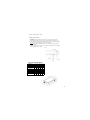
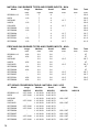
GAS HOBS
USER AND INSTALLATION
INSTRUCTIONS
Dear Customer,
Congratulations on purchasing your new product from Think Appliances.
To register your parts and labour warranty (some conditions apply please refer to your
warranty card for more details) please contact out Customer Care team on:
1800 444 357
Our Customer Care centre is there to ensure you get the most out of your appliance. For
example, should you want to learn more about recommended cooking temperatures, the
various cooking functions available, how to set and program your LED clock, and importantly
taking care of your appliance when cleaning, please call us because we are here to help you.
It is important that you read through the following use and care manual thoroughly to
familiarize yourself with the installation and operation requirements of your appliance to
ensure optimum performance.
We also carry a complete range of spare parts for all Think products. For all your spare parts
enquiries please contact our team at Pronto Parts on:
1300 306 973
Again, thank you for choosing an appliance brought to you by Think Appliances and we look
forward to being of service to you.
Kind regards
Management
Think Appliances
For future reference please record the following information which can be
found on the Rating Plate and the date of purchase which can be found in the
invoice:
Model Number
…………………….
Serial Number
…………………….
Date of Purchase
…………………….
CONTENTS
General Information
page 4
Warning and Safety Instructions
page 5
Instructions for Use
Instructions for Installation
Technical Data
pages 6–7
Pages 8–12
Pages 12–13
3
GENERAL INFORMATION
Please read this booklet thoroughly before you use this appliance. It is important that you
understand all the control functions before commencing to cook with your new appliance.
Please remember the advice and warnings shown on page 5, which is headed
‘IMPORTANT – Warning and Safety Instructions’.
This appliance is designed for domestic household use when built into a kitchen worktop.
NOTE: The housing, adjacent furniture and all materials used in the installation must be able to
withstand a minimum temperature rise of 85qC above ambient during periods of operation. This
information is for guidance only and the actual withstand temperature will depend on the
performance rating for the surface finish of the worktop.
Certain types of kitchen furniture surface finishes are particularly prone to heat damage or
discolouration at temperatures lower than the above guidelines.
Installing the appliance in contravention of the guidance given, will be at the liability of the
owner.
The use for any other purpose or in any other environment without the express agreement of the
supplier, would invalidate any warrantee or liability claim
Your new appliance is guaranteed against electrical or mechanical defects subject to certain
exclusions noted in Conditions of Guarantee.
The aforegoing does not affect your statutory rights.
In the event that you require any After Sales Service or advice, please contact the Service
Department on telephone number – 1800 444 357.
Before using this appliance ensure that any protective packaging or coatings have been removed.
To aid the protection of the environment, please sort the packing materials into different types
and dispose of them in accordance with the local waste disposal laws.
Any further information can be obtained from your local Environment Agency office.
When first used, an odour may be emitted by any residual protective finish or moisture, which
will cease after a short period of time.
This appliance has been constructed and distributed in compliance with the essential requirements
of the following EEC DIRECTIVES, EUROPEAN NORMS and AUSTRALIAN STANDARDS
and SAFETY REGULATIONS
CE Marking – 93/68 Low Voltage – 73/23 Gas Products – 90/396 / AG101
EMC – 89/336
Materials that can touch food – 89/109.
Safety Standards – EN 60 335-1, EN 60 335 – 2 – 6, EN 30-1-1, AS/NZS 3350-1, 3350-2-6.
As the supplier has a policy of continued product improvement, the right is reserved to adjust and
make any modifications deemed necessary without notification.
4
IMPORTANT NOTE – WARNING and SAFETY INSTRUCTIONS
This appliance complies with all current European safety legislation and Australian Standards,
however we do wish to emphasise that compliance does not remove the fact that surfaces will
become hot during use and retain heat after operation.
We advise that the appliance is not intended for use by young children or infirm persons without
supervision.
Young children should be supervised to ensure that they do not play with the appliance.
If it is necessary for younger family members to be in the kitchen, that they are kept under close
supervision at all times.
We also advise that great care is taken during use and cleaning operations.
Do make sure that the pan handles are always correctly positioned to avoid accidental contact.
Do not leave heated oil or fat unattended as there is a risk of fire.
Do use pans that are flat bottomed and the correct size for the heating area to be used (never
smaller).
Do not allow electrical fittings or cables to be in contact with hot areas of the appliance.
Do not use the appliance for space heating or to dry clothes.
Do not install the appliance next to curtains or soft furnishings.
Warning: in case of disassembly, maintenance and cleaning of the appliance, be careful
Please use suitable prevention and protection equipment
DO NOT SPRAY AEROSOLS IN THE VICINITY OF THIS APPLIANCE WHILE IT IS
IN OPERATION
DO NOT STORE OR USE FLAMMABLE LIQUIDS OR ITEMS IN THE VICINITY OF
THIS APPLIANCE
WHERE THIS APPLIANCE IS INSTALLED IN A MARINE CRAFT OR IN
CARAVANS, IT SHALL NOT BE USED AS A SPACE HEATER
The supplier declines any responsibility for injury or damage to persons or property as a
result of improper use or installation of this appliance.
Heat, steam and moisture will be created during use, take care to avoid injury and ensure
that the room is adequately ventilated. If prolonged use occurs, additional ventilation may
be required – please consult your Qualified Installer if you are in any doubt about the
amount required.
5
USER INSTRUCTIONS
INSTRUCTIONS FOR USE
These User Instructions should be retained for future reference and for
use by a person who is perhaps unfamiliar with the appliance.
The following models are covered by these instructions:
V4GC6
VECG6003
V3G1WC6
VECG6004
VECG6006
VECG6007
VECG7001
VECG9002
VE0260011.2
USING THE HOB
The symbols on the Control Panel fascias show which burner the Control
Knob operates.
Dependent on the model there are two methods for igniting the burners.
1. Auto Ignition
After pressing in and turning the appropriate knob anti-clockwise to the large
flame symbol,
the ignition spark will operate as long as the knob is pressed down..
When a flame has been established the knob can be released.
2. Manual Ignition
After pressing in and turning the appropriate knob anti-clockwise to the large
flame symbol,
press the ignition button located on the control panel.
The ignition spark will operate as long as the button is held down. When a
flame has been established, release the button.
To regulate the flame, continue turning anti-clockwise to the required setting
between the large and small flame symbols.
To turn the burner off, turn fully clockwise.
NOTE:
When a Thermocouple Safety Device is incorporated in the appliance, it is
necessary for the knob to be continuously held down firmly for a further period
of approximately 10 seconds after the flame has been established to enable
the thermocouple to function.
The Safety Device is designed to stop the flow of gas to the burner head in
the event of a flame out situation.
6
USER INSTRUCTIONS
HELPFUL HINTS
Abnormal Operation
Any of the following are considered to be abnormal operation and may require servicing:
Yellow tipping of the burner flame.
Sooting up of cooking utensils.
Burners not igniting properly.
Burners failing to remain alight.
Burners extinguished by cupboard doors.
Gas valves, which are difficult to turn.
In case the appliance fails to operate correctly, contact the authorised Service Department,
CUCINA Appliances on 1800 444 357
WARNING: Servicing should be carried out only by authorised personnel.
Always use the correct diameter pan, one that is the same or slightly larger than the flame ring.
The flame should never exceed the diameter of the pan.
The bottom of the pan should be flat and wherever possible, keep the lid on the pan when
cooking.
Depending on the model the following burners are provided:
Large (Rapid or Triple Crown) – for rapid cooking or boiling large quantities of liquid
Wok – for rapid cooking or boiling large quantities of liquid
Medium (Semi-rapid) – for general cooking
Small (Auxiliary)– for slow or simmer cooking
Fish Kettle – for specialised cooking
All burners are variable between full and low positions
WARNING
Do not use commercial simmering aids as these can create excessive heat, which can damage the
appliance.
CLEANING THE APPLIANCE
Always allow the appliance to cool down before cleaning to avoid a burn injury.
Do not use caustic or abrasive agents, coarse wire wool or hard tools as these can damage the
surface finishes.
Normally, wiping with a soft cloth dampened with hot detergent solution is sufficient but for
stubborn marks the following is recommended:
Vitreous Enamel parts – use only a cleaner that is recommended for this type of material.
Burner Assemblies – remove from the hob and soak for about 10 minutes in hot detergent
solution. Rinse off and dry checking that the burner holes are not clogged, then reassemble in the
correct order.
7
INSTALLATION INSTRUCTIONS
INSTRUCTIONS FOR INSTALLATION
This appliance shall be installed only by authorised personnel and in accordance with the
manufacturer's installation instructions, local gas fitting regulations, municipal building codes,
water supply regulations, electrical wiring regulations, AS 5601/AG 601 - Gas Installations and
any other statutory regulations.
Gas safety Regulations (Installation & Use)
Installation Instructions
POSITIONING THE APPLIANCE
Combustible Surfaces - Any adjoining wall surface situated within 200mm from the edge of any
hob burner must be a suitable non-combustible material for a height of 150mm for the entire
length of the hob. Any combustible construction above the hotplate must be at least 700mm
above the top surface of the bench and no construction shall be within 450mm above the top of
the burner. Allow a 10mm minimum clearance below the hotplate.
Ventilation - Ventilation must be in accordance with AS5601/AG 601 - Gas Installations. In
general, the appliance should have adequate ventilation for complete combustion of gas, proper
flueing and to maintain temperature of immediate surroundings within safe limits.
PRE-COMMISSIONING THE APPLIANCE
When unpacked, check that the following parts are included with the appliance:x Instruction and Installation Book
x Pan Supports
x Burner Assemblies
x Adhesive sealing strip and fixing clamps & screws
x ½ BSP Elbow & Seal
x LPG conversion kit comprising an LPG jet for each burner and a self-adhesive label for
amending Gas Category on the appliance Rating Label.
8
INSTALLATION INSTRUCTIONS
INSTALLATION NOTES
1. Cut the aperture to the dimensions shown below or use the template if printed on the
packaging.
2. Invert the Hob and apply the sealing agent provided to match the outer perimeter edge.
3. If the sealing agent is a strip type, the protective covering must be removed from both sides.
Do not leave a gap in the sealing agent or overlap the thickness.
NOTE: do not use any Silicone based sealant, as this can damage the worktop surface if
repairs are required.
4. Insert the appliance into the aperture and fix in position via the clamps & screws, tightening
the screws evenly (see Fig. 1 below).
Fig. 1
HOB APERTURE DIMENSIONS
VE0260011.2
595 510 560 480
33
V4GC6
595 510 560 480
33
VECG6003
595 510 560 480
33
V3G1WC6
595 510 560 480
33
VECG6004
595 510 560 480
33
VECG6006
595 510 560 480
33
VECG6007
595 510 560 480
33
VECG7001
685 510 560 480
33
VECG9002
860 510 830 480
33
9
INSTALLATION INSTRUCTIONS
VENTILATION OF ROOMS
The room in which this appliance is installed must be well ventilated by natural or mechanical
means, or a combination of both to ensure correct combustion and the removal of spent air.
The minimum quantity of air for combustion will depend on the room volume, number of
appliances and their total power rating.
The power rating of your appliance can be found by reference to the Rating Plate.
Note: The actual ventilation requirements must be determined by reference to the Statutory
Regulations in force.
GAS CONNECTION
Data Label - The Data Label is located on the underside of the appliance. A duplicate label is
supplied to adhere in an accessible area adjacent to the appliance. This appliance is suitable for
Natural Gas and Propane Gas; ensure that the available gas supply matches the Data Label.
Test Point Pressure: The appliance is factory set for Natural gas. The test point pressure should
be adjusted to 1.00kPa with the largest burner operating at maximum flame.
Natural Gas – 1.00kPa
Propane Gas – 2.75kPa
When converting from Natural Gas to Propane ensure that the NG regulator is removed and
replaced with the Test Point Assembly. A gas regulator suitable for a supply pressure of 2.75kPa
should be part of the gas tank supply. Replace the old data plate with one, which is suitable for
the type of gas for which the appliance has been regulated.
The gas supply must be connected by use of the ½ BSP Elbow, Seal and copper pipe and an
isolation tap fitted in an easily accessible position.
The appliance as supplied is for use with Natural Gas, if it is to be adapted for LPG proceed as
follows:
x Isolate the appliance from the electricity and gas supplies.
x Remove the pan supports and burner assemblies.
x Replace the injectors with the alternative type supplied.
x Use the appropriate thread sealant and check for gas soundness.
x Affix the self-adhesive label to the Rating Plate to amend the Gas Category.
Fig 2
10
Fig 3
INSTALLATION INSTRUCTIONS
GAS FLOW ADJUSTMENT
In order to adjust the minimum gas flow proceed as follows:
x Ignite the burner and turn down to the minimum setting.
x Remove the control knob from the gas tap.
x Adjust the flow either clockwise to decrease or anti-clockwise to increase the flame. Use a
screwdriver inserted down the gas tap rod or via the screw head adjacent to the rod for
models fitted with a Flame Supervision Device.
x Check that the flame is 3- 4 mm in length, bluish in colour, stable and noiseless, and does not
extinguish when changing from maximum to minimum flow.
x Replace the control knob and check that all components have been reassembled correctly.
Before Leaving - Check all connections for gas leaks with soap and water. DO NOT use a naked
flame for detecting leaks. Ignite all burners to ensure correct operation of gas valves, burners and
ignition. Turn gas taps to low flame position and observe stability of the flame. When satisfied
with the hotplate, please instruct the user on the correct method of operation. In case the
appliance fails to operate correctly after all checks have been carried out, refer to the authorised
service provider in your area.
11
INSTALLATION INSTRUCTIONS
ELECTRICAL CONNECTION
Before connecting the appliance, make sure the supply voltage marked on the rating Plate
corresponds with the mains supply voltage.
WARNING – THIS APPLIANCE MUST BE EARTHED
Ensure the appliance is plugged into a 10 amp GPO.
IMPORTANT
The wires in the main supply lead are coloured in accordance with the following code:Green and Yellow
Blue
Brown
–
–
–
Earth
Neutral
Live
The connections must be made as follows:The wire coloured Green and Yellow must be connected to the terminal marked ‘E’ or the earth
symbol (A) or coloured green and yellow.
The wire coloured Blue must be connected to the terminal marked ‘N’ or coloured blue or Black.
The wire coloured Brown must be connected to the terminal marked ‘L’ or coloured brown or
red.
NOTE: The terminals marked ‘SUPPLY’ are for the mains supply wires and the terminations
marked ‘LOAD’ are for the appliance wires.
The electrical outlet is to be positioned in an easily accessible position adjacent to the appliance.
In the event that it is necessary to replace the mains supply lead, the replacement must conform to
the specification listed in the Technical Data. Ensure that the colour code connection is correct
and that all screws are tightened correctly.
12
INSTALLATION INSTRUCTIONS
MAINTENANCE
WARNING: SERVICING SHOULD BE CARRIED OUT ONLY BY AUTHORISED
PERSONNEL
During the guarantee period, in case of need all service intervention should be referred
back to the Service Department. Please note that intervention or repair by any
unauthorised personnel will invalidate such guarantee,
Before carrying out any maintenance, disconnect the appliance from the gas and electricity
supplies.
If a gas tap becomes stiff to operate, proceed as follows:
x Remove the control knobs, pan supports, burners and hob fixing screws & clamps.
x Remove the Hob from the worktop and remove any underside protective covers.
x Disconnect the fixings holding the tap to the fascia panel, separate the assembly, then clean
the cone and seating with a cloth dampened with solvent.
x Lightly smear the cone with high temperature grease, reassemble into position and rotate a
few times. Remove the cone again and remove any excess grease making sure that the gas
ducts are not obstructed with grease.
x Carefully reassemble the components and check for gas soundness.
If it becomes necessary to replace the gas tap, proceed as follows:
x Disconnect the appliance as described above.
x Disconnect the gas pipe from the gas tap, disassemble from the gas rail by removing the
fixing screws.
x When fitting a new tap, ensure that a new gasket is used.
x Re-connect the gas tap, check for gas soundness and reassemble the hob.
TECHNICAL DATA
ELECTRICAL DETAILS
Rated Voltage
Supply Connection
Power Input
Mains supply lead
230V ac 50Hz
10 Amp GPO
0.008 to 0.02kW (depending on model)
3 x 0.75mm2 Type RR-F HAR! marked
GAS DETAILS
Connection
Type
½” BSP
Natural Gas 1.0 kPa – alternative LPG 2.75 kPa
13
NATURAL GAS BURNER TYPES AND POWER INPUTS : MJ/h
Model
VE0260011.2
VGC6
VGCWS6
V4GC6
V3G1WC6
VECG6003
VECG6006
VECG6004
VECG6007
VECG7001
VECG9002
Large
max
11.9
11.9
11.9
11.9
11.9
11.9
11.9
Medium
max
7
7
7
7
7
7
7
7
7
7
7
Small
max
4
4
4
4
4
4
4
4
4
4
4
Wok
max
12.7
12.7
12.7
12.7
12.7
12.7
Fish
max
-
Total
max
29.9
29.9
30.7
29.9
30.7
29.9
29.9
30.7
30.7
41.8
41.8
Fish
max
-
Total
max
27
27
28.7
27
28.7
27
27
28.7
28.7
39.5
39.5
PROPANE GAS BURNER TYPES AND POWER INPUTS : MJ/h
Model
VE0260011.2
VGC6
VGCWS6
V4GC6
V3G1WC6
VECG6003
VECG6006
VECG6004
VECG6007
VECG7001
VECG9002
Large
max
10.8
10.8
10.8
10.8
10.8
10.8
10.8
Medium
max
6.3
6.3
6.3
6.3
6.3
6.3
6.3
6.3
6.3
6.3
6.3
Small
max
3.6
3.6
3.6
3.6
3.6
3.6
3.6
3.6
3.6
3.6
3.6
Wok
max
12.5
12.5
12.5
12.5
12.5
12.5
JET SIZING CONVERSION TABLE: NATURAL GAS / LPG
Model
VE0260011.2
VGC6
VGCWS6
V4GC6
V3G1WC6
VECG6003
VECG6006
VECG6004
VECG6007
VECG7001
VECG9002
14
Large
NG/LPG
1.55 / 0.90
1.55 / 0.90
1.55 / 0.90
1.55 / 0.90
1.55 / 0.90
1.55 / 0.90
1.55 / 0.90
Medium
NG/LPG
1.18 / 0.69
1.18 / 0.69
1.18 / 0.69
1.18 / 0.69
1.18 / 0.69
1.18 / 0.69
1.18 / 0.69
1.18 / 0.69
1.18 / 0.69
1.18 / 0.69
1.18 / 0.69
Small
NG/LPG
0.90 / 0.53
0.90 / 0.53
0.90 / 0.53
0.90 / 0.53
0.90 / 0.53
0.90 / 0.53
0.90 / 0.53
0.90 / 0.53
0.90 / 0.53
0.90 / 0.53
0.90 / 0.53
Wok
NG/LPG
1.60 / 0.97
1.60 / 0.97
1.60 / 0.97
1.60 / 0.97
1.60 / 0.97
1.60 / 0.97
Fish
NG/LPG
-
15