1
Related Documents
Features
This installation guide is an abbreviated version of the installation procedure.
For details on the components, features, and functions of this product, refer to
the following documents on our web site, www.alliedtelesis.com:
The AT-CM70S line card is designed to support Link Test and Operations
Administration Maintenance (OAM) capability as being standardized in IEEE
802.3ah working group to support extended diagnostic services. The DIP
switches are used to set these features.
❑ AT-CV5000 Media Converter Chassis Installation Guide
PN 613-50580-00
For additional information on this line card, refer to the Converteon™ Media
Converter Line Cards Reference Guide posted on our web site,
www.alliedtelesis.com.
❑ AT-CV1200 Media Converter Chassis Installation Guide
PN 613-000331
❑ Converteon™ Media Converter Line Cards Reference Guide
PN 613-50581-00
CONVERTEON™ Family
AT-CM70S Media Converter Line Card
Installation Guide
SFP Slot, Twisted Pair Port, T1/E1 Ports, and RS-232 Serial Port
❑ AT-S70 Management Software User’s Guide
PN 613-50617-00
The AT-CM70S line card features one SFP slot, one 10/100Base-T twisted
pair port, four T1/E1 ports, and one RS-232 Serial port.
Package Contents
The SFP slot will accept one SFP transceiver that operates at a fixed
operating speed of 100 Mbps.
Make sure the following items are included in the shipping package. If any
item is missing or damaged, contact your Allied Telesis sales representative
for assistance.
❑ One AT-CM70S Line Card
Allied Telesis, Inc.
www.alliedtelesis.com
Each T1/E1 port has an RJ-48 connector.
❑ This Installation Guide and Warranty Card
The RS-232 Serial port has a mini-DIN connector.
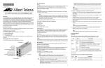
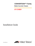
AT-CM70S Line Card Components
LEDs
The AT-CM70S line card features the following components:
Overview
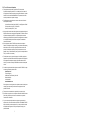
The AT-CM70S, see below, is a 10/100 Mbps Ethernet copper-to-fiber media
converter line card with Time Division Multiplexing (TDM) (T1/E1) transport, in
addition to regular Ethernet traffic along with OAM link management
capability. This line card offers support for 1.544 Mbps (T1) and 2.048 Mbps
(E1) services - with complete synchronization for toll-quality transport of
voice, video, and data. It also accommodates traditional testing equipment
currently used on SONET/SDH equipment for testing T1/E1 services.
The AT-CM70S line card can be installed in the Converteon™ Media
Converter chassis, either the AT-CV5000 or the AT-CV1200. The line card
features one small form-factor pluggable (SFP) transceiver slot, one copper
twisted pair port, four T1/E1 ports, and one console (Mini-DIN) port. The SFP
slot can accommodate one SFP transceiver that operates at a fixed operating
speed of 100 megabits per second (Mbps). The twisted pair port has an RJ-45
connector with a maximum operating distance of 100 meters (328 feet) and
operates at a speed of 10 or 100 Mbps. The line card is hot-swappable into
and out of the chassis.
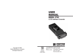
The following table lists the surface-mount diagnostic LED’s provisioned on
the Mezzanine Board and are viewable through the right side of the line card
front panel.
❑ One SFP slot (SFP transceiver sold separately)
❑ One 10/100Base-T twisted pair port with an RJ-45 connector
❑ Four T1/E1 ports with RJ-48 connectors
❑ One RS-232 Serial local console interface with 8-pin Mini-DIN connector
❑ One DIP switch
❑ LEDs
Diagnostic Mode
DIP Switch on
Base Board
SFP Expansion Slot
SFP Transceiver
LEDs
CPU RESET
Button
Console LEDs
Twisted Pair Port
LEDs
AT-C
M70
S
LK OA
M
Console Port
T1/E1
S
F
P
1
CPU RE
T1/E1 Port LEDs
Color
Description
RCL
[1 to 4]
Amber
Receive Carrier Loss occurred on the T1/E1 port.
Green
The T1/E1 port is operating normally (NML) and
has no Receive Carrier Loss.
LOTC
[1 to 4]
Amber
Loss of Transmit Clock occurred on the T1/E1 port.
Green
The T1/E1 port is operating normally (NML) and
has no Loss of Transmit Clock.
AIS
[1 to 4]
Amber
The T1/E1 has received Unframed All Ones.
OFF
The T1/E1 port is operating normally (NML) and no
AIS received.
TEST
[1 to 4]
Green
T1/E1 port is synchronized to PRBS test stream:
215-1 (E1) or QRSS (T1).
OFF
PRBS test stream not detected on the T1/E1 port.
2
T1/E1 Ports
RCL
NML
LOTC
NML
L/A
FD 100
3
4
T
X
AIS
LK OAM
LED
SET
C
O
N
S
O
L
E
RDY
AT-C
M70
S
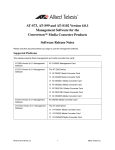
The twisted pair port has an RJ-45 connector with a maximum operating
distance of 100 meters (328 feet) and operates at a speed of 10 or 100 Mbps.
1 2
3 4
TEST
896
1 2
3 4
T1/E1
RJ-45 Port
S
F
P
1
CPU RES
ET
C
O
N
S
O
L
E
2
RCL
NML
LOT
NMLC
L/A
FD 100
3
4
T
X
RDY
AIS
1 2
3 4
TEST
1 2
3 4
*613-000333 Rev C*
613-000333 Rev C
896
1
Note
If an AT-CM70S line card is used in an AT-CV5000 chassis, it can be
managed either from its local console port or from the console port on the
AT-CV5M01 CPM module. However, if it is used in an AT-CV1200
chassis, it can only be managed from its local console port, as there is no
room for an AT-CV5M01 CPM module.
2
3
The following table lists the line card status and basic alarms LED’s
provisioned on the Base Board and are viewable through the left side of the
line card front panel.
LED
Color
Description
RDY
Green
The line card has passed diagnostics.
OFF
The line card has not passed diagnostics.
Green
The TX port has established a valid link.
Blinking
Green
The TX port has detected TX/RX activity.
Green
The TX port is operating in full-duplex mode.
OFF
The TX port is operating in half-duplex mode
(intermittently ON when there is collision).
Green
The TX port is operating at 100 Mbps speed.
OFF
The TX port is operating at 10 Mbps speed.
Green
The SFP port establishes a valid link.
OFF
The SFP port has no link.
L/A
FD
100
LK
Green
The line card is managed from its local console.
OFF
The line card is managed from the CPM
module located in the rear of the chassis.
OAM
Green
The OAM mode is enabled (visible or bypass)
and can be set by the DIP switches.
DIP Switches
The AT-CM70S line card features only the Diagnostic Mode DIP Switch,
which is located on the base board.
DIP 1
DIP 2
Link Test (non-OAM)
OFF
X
OAM Bypass
ON
OFF
OAM Visible
ON
ON
Manufacturing Default Settings
OFF
OFF
4
Caution
Before installing an AT-CM70S line card, refer to the appropriate
Converteon™ Series Chassis Installation Guide and/or the
Converteon™ Media Converter Line Cards Reference Guide the for
electrical safety and emission information.
Caution
Be sure to observe all standard electrostatic discharge (ESD)
precautions, such as wearing an antistatic wrist strap, to avoid
damaging the device. A line card can be damaged by static electricity.
1. Remove the Converteon™ line card from its shipping package and store
the package in a safe place.
3. Select two empty line card slots adjacent to each other in the AT-CV5000
chassis for the card.
4. Remove the AT-CV5PNL1 blank slot covers from the selected slots.
Keep the blank slot covers in a safe area in case you remove the line
card. The blank slot covers are used to keep dust from getting into the
chassis and maintain proper airflow, cooling, and ventilation throughout
the chassis.
6. Align the back edge of the line card with the alignment guides located
inside the slot. Avoid touching the line card components.
–- For the AT-CV5000, align with the top and bottom alignment guides.
–- For the AT-CV1200, align with the left and right alignment guides.
7. Slide the line card until the front of the card is flushed with the front of the
chassis.
The table below lists the positions of the DIP switch.
“X” means the DIP switch position could be either ON or OFF.
To install an AT-CM70S line card, perform the following procedure:
5. Locate the alignment guides in the chassis slot.
The OAM mode is disabled.
Operating Mode
Note
The Converteon™ line cards can be installed in any of the line card slots
located on the front panel of the Converteon™ chassis.
2. You must use the original package if you need to return the unit to Allied
Telesis.
CONSOLE
(applies to
AT-CV5000
chassis only)
OFF
Installing an AT-CM70S Line Card
8. Use a Phillips screwdriver to tighten the captive screws on the line card.
Note
Always tighten the captive screws to secure the line card to the chassis.
This help ensure that the connectors at the back of the line card are
securely connected to the backplane.
Caution
When used in the AT-CV1200 chassis, make sure the ground lug is
attached prior to operating the AT-CM70S line card. For grounding
instruction, refer to the AT-CV1200 Chassis Installation Guide.
5
Removing an AT-CM70S Line Card
To remove an AT-CM70S line card, refer to the Converteon™ Media
Converter Line Cards Reference Guide for instructions.
Technical Specifications
Physical, Environmental, and Electrical Rating
Dimensions (H x W x L)
1.71" x 2.89" x 5.1"
(4.4 cm x 7.3 cm x 13.0 cm)
Operating Temperature
0° C to 40° C (32° F to 104° F)
Storage Temperature
-25° C to 70° C (-13° F to 158° F)
Operating Relative Humidity
5% to 90% RH (non-condensing)
Storage Relative Humidity
5% to 95% RH (non-condensing)
Operating Altitude Range
Up to 3,048 m (10,000 ft)
MTBF (Telcordia Standards)
670,000 hrs
Power Consumption
8.5 watts
Pluggable Slot Type
SFP
Electrical Safety and Emission Statement
Standards: This product meets the following standards when installed in compliant host equipment.
U.S. Federal Communications Commission
RADIATED ENERGY
Note: This equipment has been tested and found to comply with the limits for a Class A digital device pursuant
to Part 15 of FCC Rules. These limits are designed to provide reasonable protection against harmful
interference when the equipment is operated in a commercial environment. This equipment generates, uses,
and can radiate radio frequency energy and, if not installed and used in accordance with this instruction
manual, may cause harmful interference to radio communications. Operation of this equipment in a residential
area is likely to cause harmful interference in which case the user will be required to correct the interference at
his own expense.
Note: Modifications or changes not expressly approved of by the manufacturer or the FCC, can void your right
to operate this equipment.
Industry Canada
This Class A digital apparatus meets all requirements of the Canadian Interference-Causing Equipment
Regulations.
Cet appareil numérique de la classe A respecte toutes les exigences du Règlement sur le matériel brouilleur
du Canada.
Emission
FCC Class A, EN55022 Class A, VCCI Class A, C-TICK, CE
WARNING:
In a domestic environment this product may cause radio interference in which
case the user may be required to take adequate measures.
Immunity
EN55024
Electrical Safety
UL60950-1 (cULus), EN60950-1 (TUV), CAN/CSA C22.2 No. 60950-1
Telecommunications: FCC Part 68 (TIA/EIA/IS-968); Industry Canada CS-03
ACTA Product ID – US: A5TDWNANAT-CM70S
Industry Canada Registration – IC: 3336-ATCM70S
Copyright 2006 Allied Telesis, Inc. All rights reserved.
No part of this publication may be reproduced without prior written permission from Allied Telesis Inc.
6
FCC Part 68 Customer information
a) This equipment complies with Part 68 of the FCC rules and the
requirements adopted by the ACTA. On the side plate of the chassis of
this equipment is a label that contains, among other information, a product
identifier in the format US:AAAEQ##TXXXX. If requested, this number
must be provided to the telephone company.
b) The following are required when the customer orders service from the
local telephone company:
Universal Service Order Codes ("USOC") for the Equipment: RJ48C
Facility Interface Code ("FIC"): 04DU9.1SN
Service Order Code ("SOC"): 6.0N
c) A plug and jack used to connect this equipment to the premises wiring and
telephone network must comply with the applicable FCC Part 68 rules and
requirements adopted by the ACTA. A compliant telephone cord and
modular plug is provided with this product. It is designed to be connected
to a compatible modular jack that is also compliant. See installation
instructions for details.
d) If this equipment, model AT-CM70S causes harm to the telephone
network, the telephone company will notify you in advance that temporary
discontinuance of service may be required. But if advance notice isn't
practical, the telephone company will notify the customer as soon as
possible. Also, you will be advised of your right to file a complaint with the
FCC if you believe it is necessary.
e) The telephone company may make changes in its facilities, equipment,
operations or procedures that could affect the operation of the equipment.
If this happens the telephone company will provide advance notice in
order for you to make necessary modifications to maintain uninterrupted
service.
f) If trouble is experienced with this equipment model AT-CM70S, for repair
or warranty information, please contact:
Allied Telesis Inc.
Technical Support
19800 North Creek Parkway, Suite 200
Bothell, WA 98011
1-800-428-4835
www.alliedtelesis.com
If the equipment is causing harm to the telephone network, the telephone
company may request that you disconnect the equipment until the
problem is resolved.
g) This product is not intended to be repaired by the customer (user).
h) Connection to party line service is subject to state tariffs. Contact the state
public utility commission, public service commission or corporation
commission for information.
i) If your home has specially wired alarm equipment connected to the
telephone line, ensure the installation of this US: A5TDWNANAT-CM70S
does not disable your alarm equipment. If you have question about what
will disable alarm equipment, consult your telephone company or a
qualified installer.
7