1
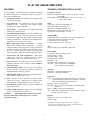
AMERITRON AL-811HD
HF POWER
LINEAR AMPLIFIER
INSTRUCTION MANUAL
The Ameritron AL-811HD is an economical 800 watt PEP output linear
amplifier that operates reliably from 160 through15 meters. The AL811HD uses four 572B tubes in a class AB2 grounded grid circuit. Heavy
duty power supply and RF components provide long service for
components. The AL-811HD/DY is shipped factory wired for 120 volt,
50/60 Hz power mains. The AL-811HDX export model is shipped factory
wired for 240 volt, 50/60 Hz power mains. The AL-811HDX/DY operates
from 160 thru 10 meters.
PLEASE READ THIS MANUAL BEFORE OPERATING THIS EQUIPMENT !
116 Willow Road
Starkville, MS 39759 USA
662-323-8211
Version 6
Printed in U.S.A.
PLEASE READ THIS MANUAL BEFORE ATTEMPTING TO OPERATE EQUIPMENT!!
UNPACKING INSTRUCTIONS
1. Carefully lift the amplifier by the bottom cabinet edge out of the shipping carton. Place the
amplifier on a firm, level surface and carefully inspect it for shipping damage. Contact the
shipper immediately if any damage exists. Save the carton and packing material for possible
shipping in the future.
2. Remove the twelve screws holding the cover on with a number 2 phillips screwdriver.
Carefully lift the cover off the amplifier. Save the screws to rescuer the cover. Note that the
AL811HD is shipped with the fuses and fuse caps inside the amplifier.
3. Locate the fuse pack with the two 12 ampere fuses and fuse caps. If additional screws are
needed, they will be in the fuse pack also. NOTE: Fuses supplied are for 120/110/100V
operation (Models AL-811HD/HDY). If you are rewiring the AL-811HD for
240/230/220V operation, you must use 8 ampere fuses. The AL-811HDX export model is
pre-wired for 240V operation and is supplied with 8 ampere fuses.
4. Remove the foam packing material (around the tubes) that secures the 572B tubes during
transit. Carefully unwrap the tubes. Do not dislodge or break the shaft that is connected to
the rear input bandswitch wafer.
5. To install the tubes in the sockets, be sure the large diameter pins line up with the two large
diameter holes in each socket. Do NOT rock or twist the tubes excessively during the
installation. If the tubes are already installed, check them for proper seating. If necessary,
press the tubes down into their sockets with gentle force. Do not rock or twist the tubes
excessively. Also, check that the anode caps are secure and that they did not come loose
during the unwrapping process.
6. The white ceramic anode connector will have to be removed from the top metal cap of each
tube if it ever becomes necessary to remove the tubes from the amplifier. This can be a
difficult procedure because the high clamping force of the internal springs in the anode
connector may hold it to the cap very tightly. The tube will break if direct upward or rocking
pressure is applied in an attempt to remove the connector. The safest way to remove the
ceramic connector is to lift the tube out of its socket. A twisting or spinning pulling motion
can then be applied while holding the ceramic connector firmly until the tube and connector
are separated. Repeat the procedure with each tube.
7. Install the cover with the vent holes to the left (near the tubes) by installing the back screws
first. Install all the screws loosely and tighten them only after all the screws are in place.
8. Install the fuses and fuse caps on the back of the unit. Read the manual to become familiar
with the operation of the amplifier.
AL-811HD LINEAR AMPLIFIER
FEATURES
TECHNICAL SPECIFICATION AL-811HD*
The AL-811HD is a grounded grid linear amplifier developed
by Ameritron using low cost 572B power triodes. It operates in
class AB2 for SSB and CW.
Frequency Coverage
Domestic model (AL-811HD): 160, 80, 40, 30, 20, 17 and 15
meter bands
Export model (AL-811HDX/HDY): 160, 80, 40, 30, 20, 17, 15,
12, and 10 meter bands.
1.
Fast Warm Up Time: The 572B tubes take approximately
10 seconds to warm-up.
2.
Long Tube Life: The 572B tubes are long life, reliable
transmitting tubes. 572B tubes offer rugged, reliable
operation even on RTTY and SSTV.
3.
Tuned Input: A Pi-Network tuned input matches the
572B tubes to 50 ohm exciters.
4.
Two Illuminated Panel Meters: The AL-811HD has two
illuminated panel meters. The Grid Current meter provides
a continuous reading of the grid current to indicate proper
loading of the amplifier. The other meter switches between
high Voltage (HV) and Plate Current (Ip).
5.
Output (7MHz)
Typical SSB PEP voice operation: over 800 watts continuous
Typical CW continuous operation: 600 watts
1/2 hour PEP two tone: 800 watts
1/2 hour continuous carrier: 600 watts
Multi-voltage Heavy Duty Transformer: A unique
"buck-boost" winding allows adjustment of primary
voltages to match a wide range of line voltages centered on
110 and 230 volts. This versatile Ameritron feature allows
the user to maintain optimum voltages on the tubes and
other components to obtain maximum performance and life.
6.
Vernier Plate and Load Adjustments: Both tuning
controls have vernier 6:1 reduction drives for smooth
tuning logging scales for accurate and rapid tune-up.
7.
Safety interlock: AC input power is removed from the
transformer when the cover is removed. Never attempt to
defeat this switch.
8.
Operate/Standby Switch: Used to remove the amplifier
from the RF line while filament and plate voltages are
maintained during "barefoot" operation.
9.
Input
Circuit type: Pi-network, slug tuned coils
Maximum VSWR at resonance: 1.3:1
Minimum 2:1 VSWR bandwidth: 15%
Maximum drive power permissible: 85 watts
Typical drive for rated output: 65 watts
ALC
Negative going, 0-12V, adjustable, phono jack
Power Supply
Circuit type: full wave bridge rectifier
No load voltage: 1700V
Full load voltage: 1500V
Full load current: 700mA
Regulation: 15%
Maximum draw at rated output: 10A (120V)
AC Input: 120V, 50/60 Hz (AL-811HD/HDY
240V, 50/60 Hz (AL-811HDX)
Metering
Multimeter: reads HV and plate current
Grid meter: reads PA grid current
XMT Indicator LED: Provides a front panel indication of
proper amplifier keying by the exciter.
Connectors
Relay: keys amplifier when grounded. Sources +12 VDC open
circuit and supplies 100mA when grounded. A built-in
pulse canceling diode protects the exciter.
RF input: SO-239, 50 ohm input.
RF output: SO-239, 50 ohms with full power, into any SWR
below 3:1.
Power: NEMA 5-15P 120V grounded style.
ALC: Phono Jack. Supplies up to 12 volts of negative voltage
for ALC control of exciters.
10. ALC: The drive level is detected to provide a control
voltage for the exciter. ALC prevents over-driving of the
linear and reduces distortion from excessive drive power.
11. Neutralization Circuit: Reduces unwanted feedback to
improve performance.
12. Grid Overload Protection: Amplifier goes into Stand-by
when too much grid current is achieved.
CAUTION:
This amplifier must be disconnected from
the power mains before removing the cover. See the
precaution on page 7.
Physical
Dimensions: 15.5" D x 13.75"W x 8.25"
Weight: 30 lbs.
*Specifications are subject to change without notice or obligation.
Exact performance measurements may vary due to the accuracy of the test
equipment and the measurement methods used.
2
GENERAL INFORMATION
The ALC circuit can be adjusted by loading the AL-811HD
slightly beyond the recommended maximum values with the
ALC line disconnected. The ALC line can then be connected
and the ALC control on the amplifier can be adjusted to a point
just before the drive begins to decrease.
SAFETY INTERLOCK
The interlock switch stays closed to allow AC line voltage to
reach the power transformer as long as the AL-811HD's top
cover is in place. When the top cover is removed, the interlock
opens and disconnects the input line voltage. This does not
discharge the bank of power supply filter capacitors. Be sure to
allow the filter capacitors to discharge before you touch
anything inside the amplifier. You can select the High Voltage
function of the Multimeter to check the high voltage potential.
WARNING: Never remove the cover of this amplifier with
the unit plugged into the power line.
NOTE: The primary use of the ALC function is the prevention
of excessive drive levels. This circuit will not prevent
small changes in output power from occurring on
different bands. Under most conditions destructive
levels of drive power are those above 100 watts. Slight
changes may occur in maximum output power on
different frequencies with the ALC connected. A
compromise in ALC adjustment may be necessary to
achieve acceptable performance on all bands.
DRIVING POWER
This amplifier is designed to operate at full ratings when it is
driven by an exciter that has approximately 70 watts of RF
output. You can use an exciter that has lower output power, but
the amplifier's output may be less. If you use an exciter that
delivers more than 70 watts, carefully adjust the driving power
to avoid "over drive" and the creation of spurious signals, which
could create needless interference to other operators. We highly
recommend that you use a monitor scope for continuous output
monitoring. The display on an oscilloscope is the best readily
available way of determining the amplitude of the voice peaks
which, if excessive, can cause "flat topping" and splatter.
PLATE SUPPLY
The power supply in this amplifier uses a combination plate,
filament and control transformer. A buck boost winding is
provided to allow the user to compensate for low, medium or
high power line voltage. This amplifier is normally supplied
wired for the highest power line voltage setting. Never change
this setting unless you are positive that performance is suffering
due to low filament and plate voltages. The life of components
will be shortened drastically if the high voltage exceeds 1800
volts at rest. The diagram on page 4 shows proper wiring for
each voltage.
IMPORTANT: Do not increase the drive power unless the
amplifier output power also increases. Grid current climbs
rapidly and the plate current meter and output power will
barely increase with excessive drive.
This condition
indicates the amplifier LOAD control needs to be advanced
to a higher number. Excessive plate current indicates the
drive power limit has been reached. Non-linear operation,
splatter, and excessive grid current will occur if the
"LOAD" setting it too low.
EXPORT MODIFICATIONS
A simple modification will allow operation on frequencies
above 15 meters. Instructions for this modification are available
by sending a written request for "Export Modification
Instructions" along with a copy of a valid amateur license.
There is no charge for this information. Export models are
shipped with this modification and have either "X" or "Y"
following the serial number. Standard frequency coverage is
indicated in the chart on page 7.
FILAMENT SUPPLY
The filament circuit of this amplifier satisfies all requirements
of the tube manufacturer related to tube performance and life.
Inrush current is controlled by the transformer's internal
resistance and impedance, filament choke resistance, and
filament wiring resistance. To insure maximum life of the tube,
never replace any circuit components or wiring with substitute
parts.
TECHNICAL ASSISTANCE
Technical assistance is available during our normal business
hours on weekdays. the following information is required to
assist you with operational problems:
•
Model and Serial Number;
•
Date of purchase and dealer;
•
An accurate description of the problem;
Meter readings at all stages of the tuning procedure are very
important along with a complete description of the other
equipment used with our product.
ALC CIRCUIT
The ALC circuit converts a portion of the RF drive voltage at
the exciter end of the tuned input circuit to a negative going
control voltage. This voltage should be used to limit the exciter
drive to safe drive levels for the AL-811HD for exciters that
develop more than 70 watts of output power.
Written assistance is also available. Due to time delays in processing
mail, please allow at least three weeks for a written reply.
AMERITRON
116 Willow Road
Starkville, MS 39759
Telephone: (662) 323-8211
Fax: (662) 323-6551
Email: [email protected]
A capacitive divider consisting of C27 and C28 is used to
reduce the RF voltage and drive a rectifier circuit consisting of
D17 and D18. The resulting voltage is filtered by C29 and R12
and is applied to the ALC potentiometer R14. R13 provides RF
and DC isolation for the ALC jack. The DC isolation prevents
loading of the exciter ALC input line by the potentiometer.
3
METERING FUNCTIONS
If the current is too low, the loading control should be turned to
a lower setting. The left meter reads PA high voltage up to
2000 volts and plate current up to 750mA. The normal readings
are 1400-1600 volts HV and 650mA of current at full rated
output with a single tone signal.
The AL-811HD has two illuminated panel meters. The right
meter reads PA grid current up to 200mA. The normal current
with a single tone (carrier) signal will be 150mA to 175mA. If
the current is too high during full power operation, the loading
control should be advanced to a higher setting.
INSTALLATION
Operation on a voltage of 240V is not required, nor will it
necessarily improve performance. The power transformer will
perform equally well with a power line frequency of 50 Hz or
60 Hz. The Transformer Connections chart at the bottom of this
page shows proper connections for various line voltages.
LOCATION
Do not operate the amplifier in excessively warm locations or
near heating vents or radiators. Be sure air can circulate freely
around and through the amplifier cabinet.
Provide an
unobstructed air inlet for the blower. Do NOT place any books,
magazines or equipment that will impede the free flow of air
near the sides of the cabinet.
WARNING: The green wire connects to the chassis of the
amplifier and it must connect to the safety
ground of the outlet.
VENTILATION
The AL-811HD ventilation system has been designed and tested
to maintain the tube temperature safely below the tube
manufacturer's rating at 500 watts output with a 100% duty
cycle. To insure proper ventilation in your installation, observe
the following:
1.
Do not block or restrict the ventilation holes in the cover.
2.
The exhaust air flow is over 20 CFM. Do not "assist" the
air flow unless the fan exceeds the AL-811HD fan CFM by
a factor of 2:1.
3.
Do not mount additional fans on the AL-811HD cabinet.
4.
The exhaust air will become warm at high power levels.
Do not place any heat sensitive objects in the exhaust air
stream.
The AL-811HDX (export model) is wired for 240V, 50/60 Hz
operation. The appropriate plug is not provided for this model.
You must wire the proper plug on the end of the power cord
supplied. Simply cut the existing plug off and wire the
appropriate plug in its place. If the line voltage in your country
is not 240V, then you must change the transformer to the
appropriate setting indicated by the chart below. Note: the AL811HD transformer allows operation on 100V line voltage in
countries such as Japan.
NEVER REWIRE THE POWER SUPPLY TO BOOST THE
HIGH VOLTAGE ABOVE 1800 VOLTS.
The wiring between the fuse box and the amplifier AC outlet
must be 14 gauge or larger in order to supply the operating
current required (10 amperes) without a significant drop in the
line voltage. The outlet should be fused for the wire gauge
GROUNDING
Connect a good earth or water pipe ground to the ground post
on the rear panel of the amplifier. Use the heaviest and shortest
connection possible.
Before you use a water pipe ground, inspect the connections
around the water meter and make sure that no plastic or rubber
hose connections are used.
These connections interrupt
electrical continuity to the water supply line. Install a jumper
around any insulating water connections you may find. Use
heavy copper wire and pipe clamps. It is best to ground all
equipment to one point at the operating position and then
ground this point as described above.
*Factory wired operation for the AL-811HD
**Factory wired operation for the AL-811HDX
used.
VOLTAGE
BUCK BOOST
PRIMARY
*120
A to 1, B TO 2
C to D, E to F
110
1 to 2, (A,B OPEN)
C to D, E to F
100
A to 2, B to 1
C to D, E to F
For 240, 230, 220 all three primary conditions apply ↓
**240
A to 1, B to 2
no connection C to D
230
1 to 2, (A,B OPEN)
D to E
220
A to 2, B to 1
no connection E to F
POWER CONNECTIONS
The AL-811HD is supplied with a NEMA 5-15P plug for 120V
operation. The power required to operate the AL-811HD/HDY
is not high enough to warrant 240V operation unless 120V is
not available. The fuses should be 12 ampere fuses for 120V
and they must be changed to 8 amperes for 240V operation.
The diagram to the right shows the proper wiring for 120V
operation.
4
INTERCONNECTIONS
1.
Connect the RF output of the transmitter or transceiver to
the RF IN connector on the rear of the AL-811HD with 50
ohm coax. Use any 50 ohm cable (RG-58 is fine) with PL259 plugs.
2.
Connect the existing station antenna system to the RF OUT
connector on the AL-811HD with any 50 ohm coaxial cable
capable of carrying 650 watts.
3.
Use shielded audio type cable with standard male phono
plugs to connect the RELAY jack on the AL-811HD to the
exciter's normally-open amplifier keying circuit. The
keying circuit in the AL-811HD has a positive 12 VDC
open circuit and it provides 100mA of current when
connected to ground. The AL-811HD has an internal backpulse canceling diode across the relay coil.
4.
Connect the shortest possible ground lead from a good
earth ground to the GND terminal. The best leads are solid
(instead of stranded or braided) copper. It is also best to
use a common ground point for all the equipment in the
station.
5.
Use a shielded audio cable with standard male phono plugs
to connect the ALC out jack on the back of the amplifier to
the negative going ALC input jack on the exciter. Do not
connect this line until you have read and understand the
function of the ALC circuit. Exciters with output powers
below 70 watts do not normally require this connection. If
this jack is connected without adjusting the ALC control,
the exciter may not develop any drive power.
TO ANTENNA
OR ANTENNA TUNER
30/20
160
80
FUSES
12A 120V
8A 240V
ALC
ADJ
ALC OUT
AUX
40
RELAY
AMERITRON
15/17
AL-811HD
RF OUT
FAN
RF IN
GND
A.C. POWER
PLUG
RF OUT
ALC
RELAY
GND
TRANSMITTER OR
TRANSCEIVER
TO EARTH
GROUND
5
TUNE-UP
MHz
1.80
1.90
3.5
3.7
4.0
7.0
7.3
CW PROCEDURE
Follow the instructions in numerical order. If the various meter
readings are different than those indicated in the instructions,
check the connections from the exciter to the amplifier and
make sure they are correct. Consult the manual for the exciter,
if necessary. Be sure the transformer is correctly wired for your
line voltage.
See the POWER CONNECTIONS
instructions on page 4 for wiring details.
Load
6 1/2
7 1/2
2
3
5 1/2
3
3 1/2
Plate
1 1/2
3
5
6
6 1/2
8
8
MHz
10.1
14.0
18.1
21.0
24.9
28.5
Load
0
3
2 1/2
4
4 1/2
5
Plate
7 1/2
9
9
9 1/2
9 1/2
9 1/2
1.
Set the AL-811HD front panel switches as follows:
POWER/OFF-ON to OFF
XMT/OPR-STBY to STBY
METER/Ip-HV to HV
NOTE: The no drive current will vary up to 25% due to
component and line voltage tolerances. During
tune up, limit Key to 7 seconds. This will keep the
tubes from overheating.
2.
Plug the line cord into a proper voltage outlet.
3.
Set the POWER switch to the ON position. The meter
lamps should light and the fan should start. Read the 2000
volt scale on the multimeter. It should indicate 1700 volts
nominally and no more than 1800 volts.
This amplifier is equipe with a electron grid overload
circuit. When peak grid current reaches 190 mA
the amplifier will go to stan-by and the red XMIT
LED will not light. Reset by toggling the Standby/ Operate Swiich
4.
With the amplifier XTM switch still on STBY, check the
VSWR of the antenna. The antenna must be 2:1 VSWR or
less to operated the amplifier. SWR above a 2:1 will have
to be tuned with a tuner between the amplifier and antenna.
( the transceiver’s internal tuner can not be used to tune the
antenna during the use of an amplifier) Turn the exciter
drive fully down after tuning.
7.
5.
Place the amplifier bandswitch on the same band as the
exciter, the PLATE control in the dial range for the
band selected, and the LOAD control as indicated:
6.
With the exciter drive still at zero, place the
METER/HV-Ip switch in the Ip position. Observe
the 750mA scale. It should read zero. Place the
XMT/STBY-OPR switch in the OPR position
8.
9.
Place the tranceiver in CW, FM or RTTY mode and
apply only enough drive to indicate a grid current of
100mA, or an Ip of no more than 450mA. Tune the
PLATE control for maximum output power. It is
normal for the plate current to dip at this point. If the
grid current goes over 200mA, reduce the drive at
once. Unkey the exciter.
Observe the output on an external RF wattmeter. Increase
the drive until 180 mA of grid current or 750 plate mA of
plate is achieved. (never to exceed 80 watts). Quickly
adjust the PLATE and LOAD controls for maximum
output power.
10. Reduce the drive until the desired output levels are
obtained.
NOTE: Rotating the LOAD control clockwise reduces grid
current for a given amount of drive. If the LOAD
control is set at too low a numerical setting, a severe
stress on tank components may occur. The PLATE
control should always be peaked for maximum grid
current or output power. Do not exceed 750mA of
plate current during tune-up.
Key the exciter (no drive). (exciter in SSB and Mic Gain
turn off) The Transmit (XMT) LED should light. Observe
the plate current on the 750mA scale. It should be 75mA.
6
OPERATION OF OTHER MODES
SSB:
Tune up the exciter and amplifier as described in TUNE UP
section and switch the exciter to SSB. Normal ranges of meter
readings on SSB are between 20 and 50 percent of the CW
carrier readings. This is due to the different peak-to-average
power ratios in the operator's speech waveform. The only true
way to measure peak output power is with a good peak reading
wattmeter or monitor scope. A whistle should produce the same
values obtained on CW. Any effort to run more than these
values will produce splatter and distortion.
NOTE: Repeated tripping of the grid overload circuit could be
due to some exciters put out short duration high
power RF pulses when first keyed. Exciter power
output peaks may reach or exceed full output level
settings even if the exciter's power control is adjusted
to deliver a fraction of full power under "keydown"
conditions.
The amplifier loading control must be set high enough
(clockwise) to prevent the grid overload from tripping and
extremely high energy levels from developing in the plate and
grid circuits of the amplifier. DO NOT "UNDERLOAD"
THE AMPLIFIER TO REDUCE POWER. Never "retune"
the amplifier to produce higher efficiency with reduced drive
except under the FM, RTTY, PACKET, and AMTOR section.
Poor linearity, splatter, or even damage to components, may
result from failure to follow instructions.
FM, RTTY, PACKET, AMTOR:
The plate current should be limited to 400mA maximum. The
grid current should be limited to 120mA and the amplifier
should be tuned for peak output power with the drive reduced to
hold the grid and plate currents below the ratings given.
QSK OPERATION
The relay in the AL-811HD takes approximately 15ms to switch
states. This precludes using the standard internal relay for QSK
CW operation. Commonly available vacuum relays are very
marginal for high speed QSK operation. At 60 WPM less than
50% of the available receive time can be used due to the slow
speed of vacuum relays.
speed switching option for operators who require high speed
switching between receive and transmit. The system switches
in one mS. Therefore, these systems are several times faster
than available vacuum tube relay systems and they allow over
90% of the available receive time to be used at 60 WPM.
The QSK-5 stand alone PIN diode switch can be used with
almost all types of amplifiers and transmitters.
No
modifications are required to the amplifier with the QSK-5.
Contact Ameritron for details on the QSK-5.
On PACKET, AMTOR and other modes delay can be added to
the transmit and receive changeover to use either vacuum or our
standard conventional relay effectively. Ameritron offers a high
The AL-811HD will operate with full output on all WARC bands except 24.5 MHz
The AL-811HDX/HDY will operate with full output on all WARC bands
STANDARD FREQUENCY COVERAGE
160 meters
80 meters
40 meters
30 meters
20 meters
17 meters
15 meters
AL-811HD
1.8 - 2.0 MHz
3.5 - 4.0 MHz
7 - 7.3 MHz
10.1 - 10.15 MHz
10.4 - 14.35 MHz
18.1 - 18.2 MHz
21.0 - 21.45 MHz
AL-811HDX/HDY
160 meters
1.8 - 2.0 MHz
80 meters
3.5 - 4.0 MHz
40 meters
7 - 7.3 MHz
30 meters
10.1 - 10.15 MHz
20 meters
14.0 - 14.35 MHz
17/15 meters
18.1 - 21.45 MHz
12/10 meters
24.9 - 29.7 MHz
WARNING!!
DO NOT ATTEMPT TO PUT THIS AMPLIFIER IN SERVICE WITH THE COVER REMOVED!
CONTACT WITH VOLTAGES INSIDE THIS AMPLIFIER CAN BE FATAL! ALWAYS DISCONNECT
THE AMPLIFIER FROM THE POWER MAINS AND WAIT FOR THE FILTER CAPACITORS TO
DISCHARGE BEFORE REMOVING THE COVER.
7
PERIODIC MAINTENANCE
The high voltage present on the plate choke and air variable
capacitors attract dust and dirt out of the air stream. It is
particularly important that the high voltage areas at the bottom
of the of the plate choke and the insulator on the air variable
capacitors be dust free. These areas should be inspected every
few months if the amplifier is operated in a dusty
environment.Unplug the line cord, and wait at least 90 seconds
until the power supply capacitors discharge.
Remove the cover and connect a jumper wire from ground to
the anode connection of the tubes.
NOTE: This is a safety wire that must be installed when
beginning service work and must be removed
when work is finished.
Use a soft bristle brush dipped in alcohol to clean previously
mentioned areas.
Amplifier Tuning Chart Log
BAND
LOAD
PLATE
160 CW
160 SSB
80 CW
75 SSB
40 CW
40 SSB
30 CW
20 CW
20 SSB
17 CW
17 SSB
15 CW
15 SSB
Fill in this chart with your actual settings and you can quickly change bands in the future.
We suggest you use a pencil as settings may change as you alter your antennas.
NOTES:
8
J4
ALC
R14
9
C44
J1
RF OUT
J2
RF IN
RELAY
J3
.
D27
C49
D26
C40
C7
C37
R13
C19
R12
C38
D18
D17
C48
R16
C43
R15
C46
C39
Q1
C45
RLY1
C4
S1A
L1
C46
RLY2
C47
Q2
D25
C3
RELAY COILS
RLY2 A
RLY1 A
C27
C28
+
L3
C1
F2
F1
BU
W
T2
C36
O
S2
GY
CN
C26
V1,2,3,4
C42
RLY1 B
C 8,9
C41
Y
INTERLOCK
L2
C35
R22
PC
R19
L4
C 10,11
C34
R21
PC
R20
PC
C12
D2
C5
C2
BK
C33
BU
PC
C32
C6
B1
AN
ON
OFF
D3
C23
D1
S1B
S3
OPR
GN
W
V
V
DL1-2
C31
C25
C13
R23
BRN
L5
W3
W2
D19-24
STBY
W4
RO
C14
L6
D4-15
L7
C18
C17
C16
C15
T1
C21-22
C20
D16
C19
R2-5
R6
BU
R9
R8
S4
R7
W1
M2
R11
R10
M1
AL-811HD SCHEMATIC
Power supply shown wired for 120V operation *
AL-811HD INPUT CHART
BAND
C3 (pF)
L1
C4 (pF)
160
80
40
100 (250-0100)
750 (250-0750)
28.75T (405-1287)
23.75T (405-1237)
13.75T (405-1137)
20/30
15/17
10/12
330 (250-0330)
120 (250-0120)
180 (250-0180)
9.75T (405-1097)
6.75T (405-1067)
4.75T (405-1047)
1300 (250-1130E)
500 (250-0500)
500 (250-0500)
120 (250-0120)
270 (250-0270)
150 (250-0150)
100 (250-0100)
PARTS LIST
Designation
Description
Ameritron Part #
B1
C1, 2, 21, 22
C3, 4
C7, 19, 37
C12
C5, 6
C8-11, 29, 30, 32 - 36
C27
C13, 31
C14
C15, 16, 17, 18
C20
C23, 25
C24
C26
C28
C38
C39 - 42 , 44 - 49
C43
D1, 2, 16, 25
D3
D4 - 15
D17, 18
D19 - 24
D26, 27
DL1, 2
J1, 2
J3, 4
L1
L2
L3
L4
L5
L6
M1
M2
Fan
0.01 uF, 250VAC/1.4KVDC Disc.
See Input Chart
0.01 uF, 50V Disc
0.01 uF, 100V Disc
2200 uF, 25V Elec.
0.01 uF, 1kV Disc
27 pF, 500V DM10
0.001 uF, 7.5kV, Disc
Air Variable
210 uF, 450V
0.1 uF,50V Disc
360 pF, 1000V DM19
500 pF, 1000V DM15
Air Variable
150 pF, 500V DM15
18pF, DM15
0.01uF, 100V Disc
100uF, 25V Elect
1N4007
MV6753 Red LED
1N5408
1N270
1N5408
1N4148
Meter Lamp
SO-239
Single Phone Jack
See Input Chart
Choke Filament
2.5mH Choke
5 1/2 inch Plate Choke
#16 Air Coil
HF Coil
Plate HV/IC Meter
Grid Current Meter
410-3583
200-2100-1B
10
200-2100
270-7220-1
200-2100-2B
250-0027
200-1100-7
282-2572-1
270-6210-7
200-3100
252-0500E
252-0360E
282-2113
250-0150
250-0018
200-2100-1
270-6100-1
300-4007
351-5002
300-5408
302-0270
300-5408
300-4148
355-0320
610-2005T
600-1003
10-15115-1
401-6250-1
10-15197
404-0811
10-13140
400-2601A
400-2600A
PARTS LIST (ctd.)
Designation
Q1
Q2
R1
R2, 3, 4, 5
R6, 7
R8
R9
R10
R11
R12
R13
R14
R15
R16
R19-22
RLY1
RLY2
S1A
S1B
S2,3, 4
S5
T1
T2
V1, 2, 3, 4
F1
F2
PC
Description
2N3904 TRANS
MJF3055 TRANS
4.7k Ohm, 1/2 Watt
50k Ohm, 7 Watt, Type 170S
1 Meg Ohm, 3 Watt
1.5 Ohm, 3Watt, Type 135
0.6 Ohm, 3 Watt, Type 135
330 Ohm, 1/4 Watt
180 Ohm, 1/4 Watt
3.3k Ohm, 1/4 Watt
10k Ohm, 1/2 Watt
100k Ohm, Potentiometer
39 Ohm, 1/4 Watt Resistor
10 Ohm, 1/4 Watt Resistor
51 Ohm, 2 Watt
DPDT Relay
SPDT Relay
Wafer Switch
Band Switch
SPST Switch
Safety Interlock Switch
Power Transformer
Neutralizing Transformer
572B Tube
12 Amp (120 Vac Operation)
8 Amp (240 Vac Operation)
Parasitic PCB
4 pc 100 Ohm, 3 Watt
8 pc 100pF DM15
4 CAP 811
Ameritron Part #
305-3904
305-3055J
101-3470
107-4500
104-6100
104-0150
104-0060
100-2330
100-2180
100-3330
101-4100
162-5100-1
100-1390
100-1100
104-1510P
408-6124
408-6114
500-4811
500-2811
507-1151
504-3247
406-1532
10-14194-H
380-0572B
755-1112-1
755-0108
50-0811-1
104-2100
250-0100
755-6811
OVERLOAD BOARD PARTS LIST
Designation
C501,3,4,5,6
C507, 08
D502
D503
IC-501
Q505
R503
R505
R506
R510
R511
RLY501
FB
Description
.01 uf 100V disc
.47 uf Tantalum
1N4007 Diode
5.6 V Zener
LM 358 dual op-amp
NPN Transistor 2N3904
10K ½ W
3.3K ¼ W
689 ¼ W
1K ¼ W
180 ½ W
DPDT 12V Relay
FB 73-801 Ferrite Bead
11
Ameritron Part #
200-2100-1
272-3470-2
300-4007
301-0752
324-0358
305-3904
101-4100
100-3330
100-2680
100-3100
101-2180
408-2135
10-15168
C507
C501
D503
+
4
R506
Fb3
FROM 12V
C503
R505
R511
C506
Ic501
+
5
+
6
7
C508
1
BLUE/WH
R503
Q505
TO CPID SENSE
W
R510
D502
C504
RLY501
C505
W
3
W
2
R/WH
TO ANT RELAY
TO STBY SW
OVERLOAD BOARD
Fb2
Fb1
DISCLAIMER
Information in this manual is designed for user purposes only and is not intended to
supersede information contained in customer regulations, technical
manuals/documents, positional handbooks, or other official publications. The copy
of this manual provided to the customer will not be updated to reflect current data.
Customers using this manual should report errors or omissions, recommendations for
improvements, or other comments to Ameritron 116 Willow Road, Starkville, MS
39759. Phone: (662) 323-8211; FAX: (662) 323-6551. Business hours: M-F 8-4:30
CST.
AMERITRON
116 Willow Road
Starkville, MS 39759 USA
662-323-8211
LIMITED WARRANTY
Ameritron warrants to the original purchaser that this product shall be free from defects in material or workmanship for
one year from the date of original purchase. During the warranty period, Ameritron (or an authorized Ameritron
service facility) will provide free of charge both parts and labor necessary to correct defects in material or
workmanship.
To obtain such warranty service, the original purchaser must:
(1)
Complete and send in the Warranty Registration Card.
(2)
Notify Ameritron or its nearest authorized service facility, as soon as possible after discovery of a possible
defect, of:
(a) the model number and serial number, if any:
(b) the identity of the seller and the approximate date ofpurchase;
(c) a detailed description of the problem, including details on the equipment.
(3)
Deliver the product to the Ameritron or the nearest authorized service facility, or ship the same in its original
container or equivalent, fully insured and with shipping charges prepaid.
Correct maintenance, repair, and use are important to obtain proper performance from this product. Therefore, carefully
read the Instruction Manual. This warranty does not apply to any defect that Ameritron determines is due to:
(1) Improper maintenance or repair, including the installation of parts or accessories that do not conform to the quality
and specifications of the original parts.
(2) Misuse, abuse, neglect or improper installation.
(3) Accidental or intentional damage.
All implied warranties, if any, terminate one (1) year from the date of the original purchase.
The foregoing constitutes Ameritron's entire obligation with respect to this product, and the original purchaser and any
user or owner shall have no remedy and no claim for incidental or consequential damages. Some states do not allow
limitations on how long an implied warranty lasts or do not allow the exclusion or limitation of incidental or
consequential damage, so the above limitation and exclusion may not apply to you.
This warranty gives specific legal rights and you may also have other rights, which vary from state to state.
42