1
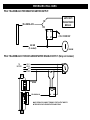
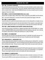
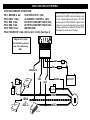
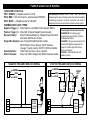
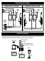
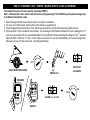
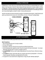
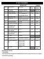
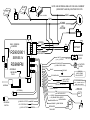
RS900/RS901 SERIES IV
RS999 FM FLASHBACK™
REMOTE ENGINE STARTING SYSTEM
INSTALLATION INSTRUCTIONS
PRE-INSTALLATION CONSIDERATIONS
To ease installation, we suggest that you READ THIS MANUAL and consider the following points before
beginning your installation:
BEFORE BEGINNING, check all vehicle manufacturer cautions and warnings regarding electrical service (AIR BAGS,
ABS BRAKES, ENGINE / BODY COMPUTER AND BATTERY).
PLAN OUT YOUR INSTALLATION and determine most suitable locations for all components to be placed. These
components include: the module itself, valet/program button, possible relays, and antenna/receiver (RS900/999FM only,
RS901 model does not include antenna or remotes.) Allow enough wire to create a service loop with strain relief, should
servicing be required. This will also allow easier access and mounting.
DAMAGE resulting from incorrect installation or failure to follow guidelines stated in this book will not be covered under
warranty and subject to repair or replacement charges.
USE A VOLT/OHM METER to test and locate all connections. Test Lights can damage a vehicle’s computer systems.
ADDITIONAL PARTS, which are not included with this unit, may be needed for your particular vehicle. . These items may
include extra relays (Part#CS-402A), General Motors Anti-Theft System Bypass modules for Vats / Passkey® / Passlock®
Systems, (Part# CS-GMATA II) or Transponder Anti-Theft Adapter modules (Part # CS-TATA).
TECHNICAL SUPPORT: (800) 998-6880
Monday - Friday 8:00am - 4:30pm Pacific Std. Time
Web Site: www.crimestopper.com
E-mail: [email protected]
CRIMESTOPPER SECURITY PRODUCTS, INC.
1770 S. TAPO STREET, SIMI VALLEY, CA. 93063
REV A - 8.2001
This device complies with FCC Rules part 15. Operation is subject to
the following two conditions: (1) This device may not cause harmful
interference, and (2) This device must accept any interference that
may be received, including interference that may cause undesired
operation. The manufacturer is not responsible for any radio or TV
interference caused by unauthorized modifications to this equipment.
Such modification could void the user’s authority to use the
equipment.
TABLE OF CONTENTS
Pre-Installation Considerations…………….………...……...………………………………………………………Front Cover
Cautions & Warnings…….………………….………..…..………………………………………………………………………2
Wiring……..……………………………………………....……………………………………………………………….…….3-5
Ignition Switch Wiring………………….…..………………………………………………………………………….………….6
Power Door Lock Wiring...……………………………………………………….………….……..…………...……..………7-8
Jumper Pin Diagram……………………….………………………………………………………………………………...……8
Improved “Smart Tachless”, Tach Reference, & Tach Finder Modes…………………………..…..……………………9-10
Transmitter / Transceiver Programming…………………………………………….…………………………...………...….11
2 Vehicle Operation.…………………………………….…………………………………..…………….………….…………12
Programming Options……...…………………………………….……………………………………….…………………12-15
Troubleshooting “Before You Call” Section……………..………………………………………….…………………...…….15
System Wiring Diagram……………………………………………………………………………………….………...………16
INSTALLATION CAUTIONS & WARNINGS
**FOR SAFETY REASONS, DO NOT INSTALL RS900/901/999FM in vehicles with MANUAL TRANSMISSIONS.** If
accidentally left in gear, a remote started vehicle could become a self-propelled threat to life and property.
DO NOT extend the RS900/901/999FM Remote start ignition harness length. Mount the module so that main harness
reaches all ignition switch wiring. Extending these wires could result in poor performance.
DO NOT route any wiring that may become entangled with brake, and gas pedals, steering column, or any other moving
parts in the vehicle.
DO NOT exceed the rated output current of any circuit on the Remote start module. Failure to observe this warning will
result in damage to the unit not covered under warranty.
DO NOT remote start the vehicle in a closed garage. Make sure that the garage door is open or there is adequate
ventilation. Failure to observe this rule could result in injury or death from poisonous Carbon Monoxide fumes.
WIRING INSTRUCTIONS
PROGRAM/OVERRIDE SWITCH: 2 PIN PLUG
This switch is used for programming features, transmitters, valet mode, and to override the optional starter disable (if
installed) in the event of a non-operating remote control.
LED: 2 PIN PLUG
The LED is used as a VALET/PROGRAMMING indicator and it will also FLASH for use as security deterrent when the
optional ANTI-GRIND/STARTER DISABLE output is programmed.
12 PIN PLUG:
PIN 1: WHITE: +12V or (-) NEGATIVE PARKING LIGHT OUTPUT:
Connect to vehicle parking light circuit at the back of light switch or if this is not possible, connect directly to one of the
parking lights at the front of the vehicle. If your vehicle has a multiplex lighting system that requires a (-) Negative parking
light output, then open the access door on the top of the module and move the jumper. SEE JUMPER PLUG DIAGRAM
PAGE 8. Some European vehicles require separate left and right circuits. Use a dual relay or diodes to isolate the output.
NOTES: (1) Default parking light output is +12 volts. (2) Use an external relay for vehicles that draw excess
current from extra running lights, light bars, or trailers. Parking light output is limited to +15/-.5 AMPS only.
PIN 2: YELLOW/WHITE: (-) HORN CHIRP/HONK OUTPUT
Connect to the Negative Horn Trigger wire usually located near the steering column. If the vehicle horn circuit requires
+12V, then a relay is required. RELAY WIRING: Connect the Yellow/White wire to terminal 85, connect relay terminals 86
and 87 to +12V constant power. Connect terminal 30 of the relay to the +12V positive Horn activation wire.
PIN 3: BLACK: MAIN SYSTEM GROUND
Connect to chassis metal of the vehicle. An existing bolt or screw may provide an adequate ground, or drill a small hole,
scrape away paint and attach using a sheet metal screw & star washer. This wire must be connected to a proper ground
or undesirable and inconsistent operation will occur. Do not use Factory ground locations.
PIN 4: YELLOW/BLACK: (-) IGNITION OUTPUT -or- ANTI-GRIND/STARTER DISABLE OUTPUT
This negative output wire is programmable and can function two different ways. It can be used as a Negative Ignition
output for GM Anti-theft and Transponder Bypass modules, or it can be programmed to function as an Anti grind/Starter
Disable output. As a Negative Ignition wire, this wire activated when the remote start button is pressed and stays on
through the duration of the remote start. As an Anti grind/Starter disable this wire activates when the Lock button on the
remote is pressed and during remote start. When using this wire for an Anti grind/Starter disable, an optional Relay is
needed to interrupt the Starter circuit. The starter disable circuit adds an anti-theft feature to this remote start system and
to prevent accidental grinding of the starter if key is turned to far after a remote start. See diagrams on NEXT PAGE.
WIRING INSTRUCTIONS
PIN 4: YELLOW/BLACK FOR NEGATIVE IGNITION OUTPUT:
ANTI-THEFT/
TRANSPONDER
MODULE
OR
YELLOW/BLACK
OR
85
86
30
87
+12V CONSTANT
3rd IGN
(If needed)
IGN SW.
PIN 4: YELLOW/BLACK: FOR ANTI-GRIND/STARTER DISABLE OUTPUT: (Relay not included)
TO
MOTOR
IGN 1
IGN 2
ACC
START
CUT
BROWN
YELLOW/BLACK
85
86
MAKE CERTAIN TO CONNECT "BROWN" START OUTPUT WIRE TO
MOTOR SIDE OF ANTI-GRIND/START DISABLE RELAY.
WIRING INSTRUCTIONS
PIN 5: TAN: (-) AUX OUTPUT (TRUNK POP)
This output will provide a ground pulse when button #3 (Trunk) on the remote transmitter is pushed to activate a factory
electric trunk release or other optional accessory. Note: this is a momentary output that will stay on as long as the remote
button is pressed and held. System will also DISARM/UNLOCK when trunk pop is activated to prevent unnecessary
triggering of Factory Alarm systems.
PIN 6: GREEN: (-) START ACTIVATION TRIGGER (RS901 Add-on model)
This wire allows a host alarm Auxiliary Channel Output or Factory Keyless Entry System (RS901) to activate a Remote
Start. A one second Ground pulse or 3 successive short pulses (when programmed) will trigger a remote start.
PIN 7: GRAY: (-) HOOD PIN SWITCH
Connect the Gray wire to a switch that is at ground when the hood is open. If an existing switch is not available, then one
must be installed. When this wire is grounded, the remote start is inhibited. If hood is opened on a remote started engine,
the unit will immediately shut the motor off. If hood is open before a remote start unit will not attempt to start engine.
PIN 8: PINK: (-) NEGATIVE DIESEL GLOW PLUG INPUT (DIESEL VEHICLES ONLY)
Connect Pink wire to indicator circuit that shows a (-) Negative signal while the “WAIT TO START LAMP” is on. On diesel
vehicles, the RS900/901/999FM systems will wait until light turns off before attempting a remote start. Note: A relay may
be required for vehicles that have a Positive wait to start lamp circuit. (Relay not included)
PIN 9: PURPLE: (+12V) BRAKE RESET
Connect the Purple wire to the side of brake pedal switch that shows +12 volts ONLY when pedal is depressed. This
is the wire that turns off the remote start once the driver’s key is in the Ignition and turned to the ON position.
PIN 10: ORANGE/BLACK: (-) OEM DISARM OUTPUT
This wire provides a Ground pulse to disarm the vehicles' Factory anti-theft system prior to a Remote Start. Connect this
wire to the vehicles' anti-theft disarm wire. This wire is sometimes found coming off the Driver's door key switch or at the
Factory Anti-theft control module. This wire may not be needed if Factory Security only requires a door unlock pulse.
PIN 11: ORANGE: (-) OEM REARM OUTPUT
This wire provides a ground pulse to rearm the vehicles' FACTORY anti-theft system after a timed-out or aborted remote
start. Connect this wire to the vehicles' anti-theft rearm wire or to the door pin circuit depending on your requirements.
This wire may be needed to pulse the door pin circuit on vehicles with retained accessory power.
PIN 12: RED/WHITE: TACHOMETER INPUT
When installing the RS900/901/999FM in Tach Ref. mode, this wire must be connected to a valid source of AC voltage.
This wire allows the RS900 to sense the engine and control the starter motor. See TACH REFERENCE MODE for more.
IGNITION SWITCH WIRING
6 PIN HIGH-CURRENT CONNECTOR:
NOTE: Heavy duty/High Current Ignition circuits
greater than 30 AMPS. Industrial vehicles, dual
AC, etc. require high-current relays. DO NOT
use the outputs of the RS900 for High-Current
systems or you will risk damaging the unit and
creating a hazardous condition! Use Part #CS403 relays for circuits up to 70 amps.
PIN 1: BROWN 14 GA.:
STARTER OUTPUT (30A)
PIN 2: GRAY 14 GA.:
ACCESSORY / IGNITION 2 (30A)
PIN 3: RED 12 GA.:
BATTERY CONSTANT FUSED (30A)
PIN 4: RED 12 GA.:
BATTERY CONSTANT FUSED (30A)
PIN 5: PINK 14 GA.:
IGNITION (30A)
PIN 6: PINK/WHITE 14 GA.: IGN 2 or ACC 2 (30A) (See Page 8)
Diagram not to scale,
for illustration purposes
only. Your vehicle may
differ.
RED
FUSE
30A
RED
FUSE
30A
PINK/WHITE
+
FUEL
PUMP
+
ENGINE
ECU
PINK
BROWN
GRAY
STARTER
-
COIL
IGN
IGN 2
OR
TRANSMISSION
ECU
ACC
ACC 2
H/V/AC
BATTERY
-
POWER DOOR LOCK WIRING
3 PIN DOOR LOCK PLUG:
PIN 1: GREEN: (-) Negative pulse for LOCK
PIN 2: RED: +12V Coil Power for external relays TERM 86.
PIN 3: BLUE: (-) Negative pulse for UNLOCK
DETERMINING DOOR LOCK TYPE: We recommend
determining the type of locking system the vehicle has before
connecting any wires. Incorrect connection will result in
damage to the remote start and/or vehicle locking system.
COMMON DOOR LOCK TYPES:
Negative Trigger (-): Many Imports, Late Model Ford & General Motors
Positive Trigger (+): Many GM, Chrysler/Dodge/Plymouth models:
Reverse Polarity:
Many Ford/Lincoln/Mercury, Dodge/Chrysler/Plymouth,
and some GM Full-size Trucks
Single Wire Systems: Late /Chrysler/Dodge/Plymouth models:
95-UP Stratus, Cirrus, Breeze, 96-UP Caravan
Voyager, Town & Country; 90-97 Ford Probe; Mazda
Semi Automatic:
Older Saab and Volvo, Isuzu, Hyundai
Electric Vacuum:
Many mid 1980’s through mid 1990’s European makes
NEGATIVE TRIGGER DOORLOCK WIRING
Crimestopper Doorlock Accessories:
CS-6600DLM: Dual-relay plug-in
module for Reverse Polarity, Positive,
or Aftermarket Motors.
CS-6500DLI: Plug-in pulse inverter that
converts the Negative outputs of the
system to Positive type for Positive
Door Lock systems.
CS-610S1: Aftermarket door lock
actuator (motor).
POSITIVE TRIGGER DOORLOCK WIRING
GREEN
GREEN
RED
RED
BLUE
BLUE
FUSED
+12V
+
85
86
87
87A 30
L
UL
FACTORY
POWER
LOCKING
RELAYS
L
UL
85
86
87
87A 30
FACTORY
POWER
LOCKING
RELAYS
POWER DOOR LOCK WIRING
AFTERMARKET MOTOR/DOOR LOCK WIRING
REVERSE POLARITY DOOR LOCK WIRING
GREEN
GREEN
FUSED
+12V
+
RED
BLUE
85
86
87
87A 30
85
FUSED
+12V
+
RED
BLUE
85
86
86
87
87A 30
87
87A 30
85
86
87
87A 30
MASTER
SWITCH
+
L
UL
CUT
CUT
JUMPER PIN DIAGRAM
Jumper pins are used to change/configure the settings of the on board IGN2/ACC2 (PINK/WHITE) and the Parking Light (WHITE)
output relays. Snap open the door on the top of the control module to access these jumper pins.
CONTROL MODULE
IGN 2 OUTPUT (DEFAULT)
ACC 2 OUTPUT
(-) NEGATIVE PARKING LIGHT (500 mA)
+12V (10A) PARKING LIGHT (DEFAULT)
SIDE VIEW
JUMPER
PLUG
JP1 JUMPERS:
ON BOARD IGN2/
ACC2 RELAY
JP2 JUMPERS:
PARKING LIGHT
OUTPUT
JUMPER
PINS
IMPROVED “SMART TACHLESS” MODE
This RS900/901/999FM systems includes a unique voltage monitor system called “Smart Tachless” mode. This mode
allows this unit to efficiently start an engine without the use of a tach signal wire. These modules actively monitor the
voltage reference on the vehicle every time remote start is requested.
IMPORTANT NOTES: (1) NO SETUP is required for the RS900/901/999FM improved “Smart Tachless” Mode (PLUG
and PLAY). (2) On the rare occasion that “Smart Tachless” mode does not operate satisfactorily, change the voltage
reference level as described below, or use a verified tach source with the red/white tach wire.
REDUCING “SMART TACHLESS” CRANKING TIME:
In the event “Smart Tachless” mode slightly over-cranks the starter motor, the settings can be changed. The purpose of
adjusting the “Smart Tachless” Mode, is to lower the voltage reference threshold [required by the unit] which reduces the
cranking time. There are two settings available: #10 (Lower) and #9 (Lowest). To set the voltage reference level ONE
step lower, follow these steps:
1.
2.
3.
4.
5.
Open hood (or ground Gray wire if no hood pin is installed)
Turn the key to the ON position
Press program button 5 times, after a few seconds the unit will flash the lights 5 times.
Carefully press the program button 10 times (you must get a light flash after each press.)
Press the Lock Button on the remote. Lights will flash once. (For RS901 Models with no remote transmitters, tap
the brake once in place of pressing the lock button on the remote)
6. Turn Ignition OFF, Close hood (or un-ground the Gray wire) and check to see if cranking time is reduced.
TO LOWER THE UNIT TO THE LOWEST REFERENCE LEVEL: Repeat steps above, however press the program
button 9 TIMES in STEP #4.
TACH (RPM) REFERENCE MODE
Tach Reference Mode provides reliable remote starting performance though engine speed sensing. When using Tach
Reference Mode, the Red/White wire is used for Tach signal [Engine RPM] input. Most modern engines include various
points where the Engine Speed [Tach] or A/C signal may be obtained. Tach Signal examples: Negative (-) side of ignition
coil, at the Distributor or Ignition Control Module, Coil Pack, Engine Computer, or Crankshaft Sensor. Sometimes Fuel
injection solenoids, and Alternator stator pins can be used. These Tach Signal locations mentioned are provided as a
guide, your vehicle may differ. Some locations will NOT be a good location for Tach source due to RF noise or Computer
Data. TACH FINDER mode will assist you in locating a valid tach source. (See Next Page.)
TACH FINDER & TACH PROGRAMMING
TACH FINDER MODE:
This system now includes a Tach Finder mode to assist in locating a valid or viable tach source for your installation.
Follow the Tach Finder steps to locate and /or verify a tach signal. When following the steps, the unit will begin to flash
the parking lights if you have the Red/White wire connected to a valid tach source. If lights do not flash, then try another
wire until you locate a tach signal that will cause the Parking lights to flash. NOTE: On some vehicles equipped with
daytime running lights, it may be difficult to see any flashing parking lights. In this case your only notification will be the
slight “ticking” sound coming out of the module from the on-board flashing light relay.
TACH FINDER:
1.
2.
3.
4.
Open hood (or ground Gray hood pin wire if no hood pin is installed)
Start Engine with the key.
Press the Program button for 2 seconds
Lights will begin flashing if the Red/White wire is connected to a valid tach source. If not try a different wire until one is
located.
5. Once Tach is located then turn off engine and close hood to abort (un-ground Gray wire).
6. See Tach Reference programming.
TACH PROGRAMMING:
1.
2.
3.
4.
5.
Open hood (or ground Gray hood pin wire if no hood pin is installed.)
Red/White wire should be connected to a valid Tach source.
Start engine with key.
Press program button 5 times, then wait for 5 light flashes.
Push program button again once. (You must get one light flash after button is pressed.) This unit is now at option
#1-Tach Learning.
6. Press the #2 Unlock Button on remote transmitter. The unit will read the Tach source and flash the lights twice for
program confirmation. (On RS901 IV models without remote transmitters, press the brake pedal in this step.)
7. If lights do not flash twice for confirmation, then try another tach source or try the tach finder.
NOTE (1): The Tach Signal locations on page 9 are provided as a guide, your vehicle may differ. Some locations
will NOT be a good location for Tach source due to RF noise or Computer Data. The RS-900 may not detect a
clean signal. Of you are unable to locate a Tach Source, call Crimestopper for Tech Support: (800) 998-6880.
NOTE (2) The RS900 will operate in “Smart Tachless” Mode [by default] unless a Tach Reference has been
programmed. This unit automatically switch out of “Smart Tachless” Mode when Tach is programmed.
900 IV TRANSMITTER / 999FM TRANSCEIVER CODE LEARNING
Transmitter/Transceiver Code Learning: (Excludes RS901)
Note: All transmitter codes must be learned at time of programming!! The RS900 IV system allows storage of up
to 4 different transmitter codes.
1.
2.
3.
4.
Open hood (ground the Gray hood pin wire if no hood pin is installed.)
Turn key to the ON position. (Doors will lock if Autolock is programmed)
Press Programming button 4 times, then after a few seconds the unit will flash the parking lights 4 times.
Press button #1 of the transmitter to be learned. You should get 2 light flashes indication the unit is waiting for a 2nd
code, then press button #1 of a second transmitter, the unit will flash 3 times indicating its waiting for the 3rd code and
lights will flash 4 times for 4th code. If all 4 codes are learned, the unit will automatically exit code learning mode,
otherwise turn key off and close hood. (See Diagram Below)
IGN
OFF
WAIT FOR
4 FLASHES
(GRAY WIRE GROUNDED)
PRESS 4X's
RS999FM
IGN
OFF
START
C RIMESTOPPER
RS900 IV
FLASH 2, 3, or 4 X's
2-VEHICLE OPERATION
An RS900 Series IV remote control can be used to Remote Start a second vehicle with an identical RS900 Series IV system
installed. Follow these steps on Vehicle #2: 1) Open hood (ground the Gray hood pin wire if no hood pin is installed.) 2) Turn Key
to the ON position. 3) Press the program button 4 times, then the unit will flash the parking lights 4 times. 4) Press Lock Button on
each of Vehicle 2 remotes (they must be relearned), lights will flash after each remote learned. Then immediately press buttons 3
and 4 (Trunk and Start) together on Vehicle #1’s remote. 5) Turn key off and close hood.
Vehicle #1 remote will now remote start Vehicle #2 by pressing the Trunk AND Start buttons together. Vehicle #1 Remote cannot
perform any functions other than remote start on Vehicle #2 (No Lock, Unlock, or Trunk pop). See Diagram Below.
2 VEHICLE OPERATION
START
+
UNLOCK
LOCK
START
TRUNK POP
VEHICLE
1
VEHICLE
2
VEHICLE 1
REMOTE
START (ONLY)
OPTION PROGRAMMING
This system has several installer programmable features as listed in the chart on next page.
Option Programming:
1. Open hood (ground the Gray wire if no hood pin is installed)
2. Turn Key to the ON position
3. Press program / valet button 5 times, after a few seconds the unit will flash the lights 5 times.
4. Push the valet/program button [again] the number of times that corresponds to the option number desired. You must get a
light flash after each button press. See chart on next page for option list.
5. A) For RS900/999FM: When you reach the desired programming level, Press button #1(Lock) or #2 (Unlock) to change
the option.
5. B) For RS901 (No remotes) Tap the brake pedal once to change the option (Same as pressing Button 1 on the remote)
or tap the brake pedal 2 times (Same as pressing Button #2 on the remote)
6. Turn Ignition OFF, Close hood and check for changed features. Change each option individually repeating #1-5.
OPTION PROGRAMMING
Option # Option Description
1.
2.
3.
4.
5.
6.
7.
8.
OPTIONS CHART
Option Values
Tach Learning
Autolock with Ignition
Door Lock Pulse Time
Tach Reference (Page 10)
ON or OFF.
0.75 Sec. (Standard) OR
3.0 Sec. (European Vacuum)
Double Unlock Pulse
ON or OFF
OEM Interface
Remote Start w/Single Pulse or
3 Pulses on Green input wire
Passive Starter Disable
ON or OFF
Horn Chirps on remote start ON or OFF
Button #1
LOCK
ON
3 Sec.
* = DEFAULT
Button #2
UNLOCK
Learn Tach
OFF*
0.75 Sec.*
ON
3 pulse
OFF*
1 Pulse*
ON
ON
OFF*
OFF*
ON or OFF
OFF
ON*
ON or OFF
OFF
ON*
ON or OFF
OFF
ON*
11.
Lock During and After
Remote Start Abort
Smart Tachless Reference
Voltage Setting #9
Smart Tachless Reference
Voltage Setting #10
NOT USED
12.
Yellow/Black Wire (-)
(-) IGN output or (-) Anti-Grind
Anti-Grind
IGN output*
13.
Remote Start Engine Run
Time
12 Min.
24 Min.*
14.
Option reset
Button #1 = 12 Min.
Button #2 = 24 Min.
Button #3 = 36 Min.
Button #4 = 48 Min.
Button #2
9.
10.
NOT USED
Reset ALL to
Default
PROGRAMMABLE OPTIONS:
1. Tach Learning:
The unit will program the Tach signal from the Red/White wire when button 2 is pressed at this option level. See pages 910 Tach Ref/Tach programming.
PROGRAMMABLE OPTIONS
2. Auto Lock/Unlock with Ignition:
Controls whether the doors will automatically lock when the ignition is turned on and will unlock when turned off.
3. Door Lock Pulse Time:
Controls the amount of time (0.75 sec. or 3 sec.) for the lock/unlock pulse. The standard setting is .75 which covers for most
vehicles. The 3 sec. setting may be required for 1980’s/90’s European Vehicles that require a 3 second long pulse to operate
Vacuum or Pneumatic door lock systems.
4.Double Unlock Pulse:
The unit will send 2 unlock pulses when the #2 Unlock button is pressed. This feature may be required for interfacing this alarm
with an existing Factory Keyless Entry or Alarm system in a vehicle. These systems are found on some Nissan, VW, Toyota, and
Lexus vehicles.
5. OEM Interface (RS901 Add-on Model):
This option controls this input selection for the Green Negative Start Trigger Wire. When using an Aftermarket Host Alarm or
Keyless Entry System: Leave the setting as “1 pulse” and connect the Green wire to the (-) Auxiliary output wire of the Alarm or
Keyless Entry System. For Factory Keyless entry systems (without a <-> negative auxiliary output), change the option to “3 Pulse”
and tap the green wire into a Negative signal wire on the vehicle such as a Negative door lock wire. Pressing the Factory remote
lock button 3 times will produce 3 short negative signals to trigger a remote start.
6. Passive Starter Disable:
Note: Yellow/Black Negative Output must be programmed as an “Anti-Grind” for this feature. See option 12.
This option controls the unit’s Negative Anti-Grind output allowing it to come on automatically 1 min after the ignition has been
turned off. Note if you set this system up for a Passive Starter Disable/Anti-Grind, you must use the remote control UNLOCK
button when returning to the vehicle to deactivate it over vehicle will not start with key. This option allows the unit to act as a
passive immobilizer.
7. Horn Chirps on Remote Start:
This option adds usability to the unit’s Negative horn honk/chirp output allowing for an additional 3 short chirps when requesting a
remote start via the remote.
8. Lock During/After Remote Start:
This option controls whether the unit will automatically lock during and after a remote Start abort or time-out.
9. & 10. Smart Tachless References:
These options change the Voltage reference when using “Smart Tachless” mode to reduce crank time. See “Smart Tachless”
mode section on Page 9.
11. No Option, Not used
PROGRAMMABLE OPTIONS
12. Yellow/Black (-) Negative IGN or ANTI-GRIND Output:
This option controls the units Negative multi-function output. Default: It is a Negative IGN output that turns ON and stays on for the
duration of the remote start. Use this wire to turn on Anti-theft bypass adapters for GM or Transponder systems. When changed to
an Anti-Grind, this output activates and deactivates with Lock/Unlock buttons on the remote. Anti-Grind is designed for use with an
optional Starter kill relay (Not included).
13. Run Time: This option controls the engine run time for remote start. Choices are 12, 24, 36, or 48 minutes.
14. Option reset: Provides a “reset” to restore all options to the default position as seen in the chart on Page 13.
TROUBLESHOOTING: “BEFORE YOU CALL” SECTION
UNIT FLASHES LIGHTS ONCE AND WILL NOT ATTEMPT A START:
The unit is in Valet mode. Turn IGN ON, press and hold valet/programming button for about 5 seconds then turn key off. Unit is
now out of valet mode and should perform a remote start. If optional LED is installed, then it will be on solid when in Valet.
UNIT FLASHES LIGHTS TWICE AND WILL NOT ATTEMPT A START:
The unit senses a fault at the Brake (Purple wire is active) or the Hood is OPEN (Gray wire grounded). This is a safety feature of
the unit. Check installation for faults and make sure hood is closed and latched and brake wire is not active.
UNIT CRANKS VEHICLE BUT ENGINE NEVER STARTS: (2 parts)
1. In some vehicles, there may be a Factory anti-theft system that will not allow the engine to run without the key in the ignition.
These systems may include Factory Security Modules, GM Passkey®/Passlock®, and RF Transponder systems (Ford
P.A.T.S.®). Many late 1990’s and later vehicles include some type of Anti-Theft system which may require a bypass module.
2. The vehicle may have more than one Ignition/or Accessory circuit that requires power for the vehicle to start. This is common
on some GM/Toyota vehicles.
VEHICLE STARTS BUT CHECK ENGINE LIGHT COMES ON OR ENGINE RUNS BADLY: (2 parts)
1. Many 1990-UP General Motors cars/trucks require a secondary ignition circuit for the Transmission computer and other on
board systems. If the vehicle is started without this wire energized, there may be a “Check Engine” or “Service Engine” light on
the dash. This may cause damage if the vehicle is driven in this condition. Be sure to check for and additional WHITE (or
sometimes GREEN) Ignition wire on GM cars and trucks. Connect the Pink/White IGN#2 wire to this circuit in the vehicle.
2. Some Vehicles (Commonly Nissan) require 2 Start (Cranking) circuits for the vehicle to run properly. If this is the case, then an
additional relay must be installed (triggered off of the BROWN start output wire). Connected to the Extra start relay output to
the extra start wire in the vehicle. Secondary starter wire may be a smaller wire than the primary starter wire.
NO RESPONSE FROM EITHER TRANSMITTER: (2 Parts)
1. Check for proper power/ground wiring connections at module.
2. Check Antenna Module connection. The antenna module included with this system must be plugged in.
ENGINE
ECU
TRANSMISSION
ECU
+
NOTE: USE EXTERNAL RELAYS FOR HIGH-CURRENT
(GREATER THAN 30A) IGNITION CIRCUITS.
FUEL
PUMP
-
ACC
H/V/AC CONTROL
COIL
IGN
IGN#2
OR
ACC#2
STARTER
BROWN
GRAY
RED
RED
PINK
PINK/WHITE
IGN2 / PARKING
JUMPERS
RS900/901
+
30A
FUSE
BATTERY
FUSE
30A
SERIES IV
WHITE
(+) or (-) OUTPUT
RS999FM
PARKING
LIGHTS
+15A or -.5A
YELLOW/WHITE
(-) HORN CHIRP / HONK
ANTENNA/
RECEIVER
PLUG
BLACK
FACTORY
HORN
GROUND
(-) IGNITION
or ANTI-GRIND
RELAY OUTPUT
YELLOW/BLACK
(-) AUX. OUTPUT
(TRUNK POP)
TAN
TO HOST ALARM or KEYLESS
AUX. CHANNEL OUTPUT
WIRE (RS901 MODEL)
GREEN
(-) START ACTIVATION
ANTENNA
GRAY
(-)HOOD SWITCH
(OPTIONAL)
DIESEL WAIT
TO START LAMP
PINK
(-) GLOW PLUG INPUT
LED
WAIT
PURPLE
(+12V) BRAKE PEDAL RESET
PROGRAM
SWITCH
(-) UNLOCK OUTPUT
+12 V FOR RELAYS
(-) LOCK OUTPUT
BLUE
RED
GREEN
-
ORANGE/BLACK: (-)OEM DISARM
ORANGE: (-)OEM REARM
3
6
2
7
1
8
RED/WHITE
TACH INPUT
4 5
0
TACH