1
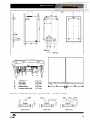
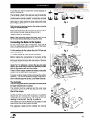
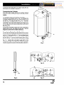
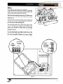
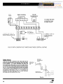
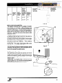
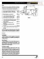
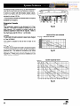
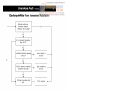
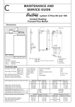
cCJ
System Plus
Duo 55
Installation and Operating
Instruction Manual
Including
User Instructions
Chaffoteaux et Maury Ltd., as a leading manufacturer of
domestic and commercial water heating appliances, as
well as domestic unvented direct and indirect storage
cylinders, is committed to providing high quality products
and a first class after sales service. If it is necessary to
contact an engineer, then telephone your local
Chaffoteaux Service Centre.
Advice on installation or servicing can also be obtained
by contacting the Chaffoteaux Customer Services
Department.
CUSTOMER SERVICES DEPARTMENT
Tel: 01952 222288 / Fax: 01952 224028
LOCAL CHAFFOTEAUX SERVICE CENTRE
Tel: 0807 2430224
The manufacturer’s
guarantee against faulty
manufacture or materials for the cylinder is 5 years and
for the electrical components, thermal controls and safety
valves is for 12 months, from the date of purchase.
The guarantee will be invalidated if the factory fitted
temperature and pressure relief valve is tampered with
or removed. The Manufacturer or Distributors cannot
be held responsible for any damage howsoever caused
and which is a consequence of the removal or tampering.
The guarantee may also be invalidated if the appliance
is not installed by a competent person in accordance
with the recommendations made herein, current
standards, regulations or in a manner not approved by
the manufacturer, modified in any way, subjected to frost,
misuse or neglect, and that factory fitted parts have had
unauthorised repairs or replacements carried out.
Evidence of purchase and the date of supply must be
made available at the time of any claim.
To assist us in providing you with an efficient after
sales service,
please
return
the guarantee
registration card enclosed with the cylinderwithout
delay.
The installation of this appliance must be carried out by
a licenced installer and who is a CORGI Registered
person or other competent person and in accordance
with the requirements of the Gas Safety (Installation and
Use) Regulations and the Building Regulation Approved
Document G3.
In addition, the installation must also comply with the
current byelaws of Local Water Undertakings, Building
Regulations, IEE Wiring Regulations, Local Authority
Building Standards (Scotland) Regulations and the Safety
Document 635 The Electricity at work Regulation.
part 1, BS 7593, BS 6789, BS 5546, BS 4814, BS 7074
parts 1 and 2, BS 7671 and BG DM2.
Precautions: During servicing, keep the dust generation
to a minimum and avoid inhaling any dust and contact
with the skin and eyes. Normal handling and use will
not present any discomfort, although some people with
a history of skin complaints may be susceptible to
irritation. When disposing of the lining, ensure that it is
securely wrapped and wash hands after contact.
It should also be carried out in accordance with the
current editions of the following British Standards Codes
of practice: BS 6981, BS 5440 parts 1 and 2, BS 5449
Installation must be carried out by a suitably qualified
installer and in accordance with current regulations
and codes of practice.
l
No valve should be fitted between the expansion relief
valve and the storage cylinder.
Only the safety valves supplied with the DUO 55
cylinder should be used.
The discharge pipe must be terminated where it is
visible and will not cause danger to people in the
vicinity of the discharge.
The DUO 55 cylinder must not be used without the
safety valves and expansion vessel.
Note: The discharge could consist of scalding water and
steam.
l
The boiler, cylinder and ancillary controls must be
adequately maintained.
The installation must have a sufficient and constant
supply of mains fed cold water.
l
Only Chaffoteaux approved replacement parts should
be used.
Customer Care ...............................................
.I
Guarantee ......................................................
.I
Commissioning ........................................
16-l 7
DHW .................................................................. 16
Central Heating .................................................. 16
Lighting the Boiler.. ............................................. 17
Statutory Requirements .................................. .2
Post Commissioning ....................................
Safety Notice ..................................................
.2
Contents .........................................................
.3
Specifications .................................................
.4
Britony System Plus 60 ....................................... .4
DUO 55 Cylinder ................................................. .4
Weights ............................................................... .4
Minimum Clearances ........................................... 4
Outer Case Dimensions for Cylinder & Boiler ..... .4
Dimensions ....................................................
.5
Location of Components .............................
6-7
System Guidance ....................................
18-20
Flue ....................................................................
Ventilation ...........................................................
Gas Supply.. .......................................................
Electrical Supply .................................................
System Pressure ................................................
Flushing & Water Treatment ..............................
System Controls .................................................
Bypass & Pump.. ................................................
Expansion Vessel ...............................................
Filling Point.. .......................................................
Maintenance.. ...............................................
The Cylinder.. ....................................................... 6
Location of Components ...................................... 6
The Safety Controls Pack.. ................................... 7
Introduction ....................................................
.8
Operation ....................................................
8-9
Installing the Boiler .......................................
.I0
Planning .............................................................
Location .............................................................
Safety Notice ......................................................
Installation ...............................................
e
18
18
18
18
19
19
19
19
20
20
.21
Routine Maintenance ......................................... 21
User’s Instructions.. .................................
21-22
Switching On ......................................................
Heating ...............................................................
Hot Water.. .........................................................
To Turn Boiler Off Completely ............................
Operational Faults ...................................
22
22
22
22
23-24
10
10
10
1O-14
Positioning the Boiler & Cylinder on the Wall.. ....
The Boiler.. .........................................................
The Cylinder ........................................................
Making the Electrical Connections .....................
Safety Valves .....................................................
Fitting the Horizontal Flue.. .................................
Refitting the Outer Cases ...................................
C&M
-.-
.I7
10
10
11
13
14
15
15
3
BRITONY SYSTEM PLUS 60
Appliance category .................................... Cat II 2H3+
Heat input C/H & DHW
Maximum in kW.. ................................ 20.22
Maximum in Btu/h ............................... 69005
Heat output C/H & DHW
Maximum in kW.. ................................
Maximum in Btu/h ...............................
C/H circuit pressures
Min operating in bar
in ib/in*
Max operating in bar
in ib/in2
Safety discharge
in bar.. .................................................
in ib/in3 ................................................
Expansion vessel
Pre-charge pressure in bar.. ...............
Pre-charge pressure in lb/in2 ..............
Net capacity at 3 bar in litre ................
18
61428
0.7
:p5
36.6
3
43.5
0.7
9.4
5.44
NATURAL GAS G20
Gas rate
Maximum in m3/h ................................ 2.14
Maximum in ff/h ................................. 76
Inlet pressure
Nominal in mbar ................................. 20
Nominal in in wg ................................. 8
Adjustable by-pass
Minimum flow rate in I/h ......................
Minimum flow rate in gal/min ..............
Maximum flow rate in I/h .....................
Maximum flow rate in gal/min .............
100
0.36
700
2.56
Electrical characteristics
Supply.. ............................................. 230V - 50Hz
Consumption .............................................
Protection ...........................................
Fuse no 1 ............................................
Fuse no2 ............................................
External controls .................................
150W
IP 44
2A
1.25A
24V
DUO 55 CYLINDER
Storage capacity in litre ............................. 55
Max water supply pressure to
pressure reducing valve ............................ 12 bar
Operating pressure ................................... 3 bar
Expansion vessel charge pressure ........... 3 bar
Expansion valve setting.. ........................... 6 bar
Maximum primary working pressure ......... 3.5 bar
Set opening pressure of combined
temperature and pressure relief valve.. ..... 90°C
....... 7 bar
Heating capacity of the primary heat
exchanger ................................................. 23 kW
Heating duration
(primarytemperature90°C flow @
Im3/hr DHW temperature @ 15°C
raised to 65°C in mins) .............................17 min
Burner pressure
Nominal in mbar ................................. 6.7
Nominal in in wg ................................. 2.7
Consumption per day to maintain
the temperature @ 65°C in kWhr/24hr ...... 0.04
70% reheat time ........................................ 13 min
Burner injector diameter
Natural gas G20 in mm.. ..................... 1.23
WEIGHTS
Britony System
PROPANE L.P.G. G31
Gas rate
Maximum in kg/h ................................ 1.55
Maximum in fRh ................................. 3.42
Inlet pressure
Nominal in mbar ................................. 37
Nominal in in wg ................................. 14.8
Burner pressure
Nominal in mbar ................................. 21 .O
Nominal in in wg ................................. 8.4
BUTANE L.P.G. G30
Gas rate
Maximum in kg/h ................................
Maximum in Lbs/h ..............................
Inlet pressure
Nominal mbar .....................................
Nominal in in wg .................................
1.58
3.48
28
11.2
Burner pressure
Nominal in mbar .................................
Nominal in in wg .................................
Burner injector diameter
LPG G30 and G31 in mm ................... 0.70
4
Plus 60
With packaging.. ........................................ 43.2 kg
Without packaging.. ................................... 41.2 kg
Lift weight .................................................. 35.2 kg
Cylinder
Weight when empty.. ................................. 33 kg
Weight when full ........................................ 90 kg
MINIMUM CLEARANCES
Both sides .................................................
Above casing .............................................
Below casing .............................................
Front (for servicing) ...................................
Front (in operation) ....................................
OUTER CASE DIMENSIONS
BOILER
5 mm
170 mm
200 mm
500 mm
5 mm
FOR CYLINDER
Width .........................................................
(minimum space required 450)
Height.. ......................................................
Depth.. .......................................................
Minimum space required when cylinder
and boiler fitted side by side ......................
440
850
380
895
&
,
,
,
,
,
,
,
,
,
,
,
,
,
,
,
,
,
,
,
,
,
,
,
,
,
,
,
,
,
,
,
,
,
,
,
,
,
,
J
K
L
N
0
3
:
i
Ir
67
j
I
-
I
I
I I I
I
I
I
I I
I
I
I
I
-+--I
I
-8
+380+
Heating flow
H.W. flow
Gas supply
Heating return
Pressure relief outlet
TypeClZorC42
e
b
~~+~
022mm
022mm
022mm
022mm
I
I
015mm
The boiler is suitable for the 4 flue types: *type Cl2 or C42
C&M
-.-
445
Type C 32 xx
l
type C32 xx or C32 xy
Type C 32 xy
5
The Cylinder
The Chaffoteaux et Maury BRITONY DUO 55 is designed
for use as an unvented storage cylinder heated indirectly
by a BRITONY SYSTEM PLUS 60 boiler. The cylinder
is supplied with a safety controls pack and expansion
vessel to allow it to be connected to the main cold water
supply. The cylinder is stainless steel with a high power
coil. It is contained within a white case insulated with a
preformed polystyrene jacket.
Location
of components
1.
2.
3.
4.
5.
Air pressure switch
Steel chassis complete with expansion vessel
Main heat exchanger
Combustion chamber
Multi-gas burner assembly comprising ignition
and ionisation electrodes
6. Automatic air separator and automatic vent
7. Heating circuit flow switch
8. Pump
9. Electrical box
11. Overheat thermostat
12. Gas valve assembly
13. Sealed chamber
14. Flue hood with fan
16. Primary circuit control thermistor
17. Three way valve
18. CH Flow isolating valve
19. Two position selector switch
20. User’s instruction panel
21. Heating flow temperature adjustment
22. Green indicator - Power ON
23. Orange indicator - Burner ON
24. Red indicator - Lock out / flame failure
25. Reset button
26. Pressure gauge
27. Gas service tap
28. Hot water flow isolating valve
29. CH Return isolating valve
30. Pressure relief valve (boiler)
32. By pass
33. By pass adjustment screw
34. Location of central heating filter
35. Expansion relief valve also used for draining
cylinder
36. Pressure reducing valve
37. Discharge pipe to tundish
38. Cold water inlet
39. Return to boiler
40. Hot water outlet
41. Cylinder thermostat phial position
42. Flow to coil
.6
,7
8
27
6
29
30
m
--
44. Temperature selector
Flow and Return flexible pipes (not visible)
45. Temperature and pressure relief valve
46. Chassis
47. DHW expansion vessel
48. Cylinder
49. Pressure test point
The Safety Controls
19
21
20
22
26
Pack
To enable the cylinder to comply with the current
regulations it is supplied with a safety controls pack.
This comprises:
Pressure regulator with integral strainer to ensure a
constant pressure to the hot water system
44
(non return valve) to prevent the back
feeding of hot water to the cold main.
Check valve
vessel to take up the expansion of the water
Expansion
when it is heated.
Expansion relief valve to prevent over expansion of
the water in the system (also used as drain-off for
cylinder).
Pressure
relief valve to prevent over pressurisation of
the system.
relief valve to provide a safety outlet in
Temperature
the event of overheating.
Cylinder thermostat
18
28
27 33
29
to control the temperature of water
in the cylinder.
to collect and provide an air break for the
discharge pipes from the temperature and pressure relief
valves. The discharge must be terminated in a safe
and visible location.
Tundish
42
48 -
40
39
38
37
C
36
View from underneath cylinder
e
C&M
-.-
7
The Chaffoteaux et Maury BRITONY DUO 55 is a
combination of an unvented stainless steel storage
cylinder heated indirectly by a fanned flued sealed
system boiler within matching outer cases. It benefits
from the high efficiency provided by the modern low
water content BRITONY System Plus 60 boiler and a
high power coil within the cylinder. A combination
providing very fast reheating of the hot water.
For greater flexibility of installation, the cylinder could
be fitted below, on the right or the left of the boiler or
separately from the boiler. Supplied directly from the
main water supply the cylinder does not need a separate
feed cistern or vent pipe in the loft space.
The BRITONY DUO 55 provides central heating as well
as hot water. The boiler is designed for sealed systems
only and a circulating pump, diverter valve, expansion
vessel, a pressure gauge and safety valve are included
within the boiler.
with an expansion vessel, pressure reducer, strainer,
check valve, temperature and pressure relief valve,
expansion relief valve. The cylinder has been tested
and approved by the WRc as meeting with the
requirements of EN 60335 2.21 and EN 60529. The
boiler has been tested and approved to carry the CE
mark.
The BRITONY DUO 55 can be installed with the
standard horizontal flue, raised horizontal, concentric
vertical, twin pipe or SE duct flue arrangements.
Adapters, bends and other accessories are available
on request.
The
1.
2.
3.
4.
The cylinder has a capacity of 55 litres and provides the
advantages of mains pressure and greater volumes of
hot water to taps and showers. It is supplied complete
Domestic
Hot Water Mode
To be able to supply hot water, the selector switch
(19 Fig. 1) must be in either in*
or ‘1111
2
position.
This will confirmed by the green Indicator light 0 (22
Fig. 1).
DUO 55 is packed in four cartons:
The boiler
The flue assembly and fixing kit
The cylinder with the safety controls pack, fitting
template and instructions manual
Connections and plinth to close couple the boiler
and cylinder.
The boiler will now stay in the hot water mode for three
minutes (this can be set to 30 seconds if required. See
Commissioning section).
Priority will be given to a demand for reheating the
cylinder.
The hot water temperature in the cylinder can be
adjusted between 50°C and 70°C using the control knob
on the control panel of the cylinder (44 Fig. 2).
When the cylinder thermostat is calling for heat, it
switches the 3-way valve (17 Fig. 3) to the hot water
position. The hot water from the primary circuit is then
diverted through the cylinder coil to heat DHW.
25
The first stage solenoid (12a Fig. 3) and safety solenoid
(12~ Fig. 3) open together to allow gas to the burner.
The ignition sequence begins and a continuous high
speed spark ignites the gas. As soon as a flame is
detected the orange indicator bulb& (23 Fig. 1) will light
and the second stage solenoid (12b Fig. 3) opens to
allow the full gas rate.
19
21
22
Fig. 1
If a flame is not detected, after eight seconds, the
security solenoid closes and shuts off the gas.
The red lockout indicator bulbjft (24 Fig. 1) will light.
Press the RESET button to attempt to relight.
The hot water flow temperature is controlled by the
primary circuit control thermistor (16 Fig. 3).
When the cylinder thermostat is satisfied, the burner is
extinguished and the pump stops.
44
Fig. 2
26
Central
Heating Mode
To be able to supply central heating, the selector switch
(19 Fig. 1) must be in ‘~~~~
3
position. This will be
confirmed by the green indicator light 0 (22 Fig. 1).
When there is a demand for heating (either from the
room thermostat or the external programmer) and the
boiler temperature control is calling for heat.
The pump starts and at a flow rate of 4ltr/min the central
heating flow switch operates allowing the ignition
sequence to begin.
The first stage solenoid (12a Fig. 3) and safety solenoid
(12~ Fig. 3) open together to allow gas to the burner.
The ignition sequence begins and a continuous high
speed spark ignites the gas. As soon as a flame is
detected the orange indicator bulb 0 (23 Fig. 1) will
light. After 45 seconds the second stage solenoid (12b
Fig. 3) opens to allow the full gas rate.
If a flame is not detected, after eight seconds, the
security solenoid closes and shuts off the gas. The red
lockout indicator bulb f (24 Fig. 1) will light. Press the
RESET button to attempt to relight.
I&
11
-------4
17
The central heating flow temperature is controlled by
the central heating control thermistor (16 Fig. 3).
The boiler has been designed to minimise cycling and
will not attempt to relight for at least 3 minutes after the
boiler thermostat has been satisfied (this can be set to
30 seconds if required, see maintenance and service
guide).
When the room thermostat is satisfied the burner will
switch off and the pump will remain running for a further
3 minutes.
27
Fig. 3
Note: It is possible to override the 3 minute delay by
pressing the RESET button (25 Fig. 1).
e
C&M
-.-
9
Planning
Safety Notice
Installation must be carried out by a suitably qualified
installer and in accordance with current regulations
and codes of practice.
Please ensure that you are familiar with the installation
requirements as well as the relevant British Standards
and Statutory Regulations (see page 2) before
commencing work.
Only the safety valves supplied with the cylinder
should be used.
Location
The DUO 55 can be installed on any suitable internal
wall. Provision must be made to allow the correct routing
of the flue and siting of the terminal to allow the safe
and efficient removal of the flue products. The appliance
may be installed in any room, although reference must
be made to the IEE regulations if it contains a bath or
shower. A compartment or cupboard may be used
provided that it has been purpose-built or modified for
the purpose. It is not necessary to provided permanent
Detailed
ventilation
for cooling purposes.
recommendations are given in BS 5440 pt. 2. If it is
proposed that it is installed in a timber framed building
then reference must be made to British Gas Document
DM2, or advice sought from CORGI.
The cylinder must not be used without the safety
valves and expansion vessel.
The boiler, cylinder and ancillary controls must be
adequately maintained.
The installation must have a sufficient and constant
supply of mains fed cold water.
No valve should be fitted between the expansion relief
valve and the storage cylinder.
The discharge pipe must be terminated where it is
visible and will not cause danger to people in the
vicinity of the discharge.
Note: The discharge could consist of scalding water and
steam.
l
The installation kit comprises four cartons:
1. The Boiler
Installation and Maintenance Instructions (for
the boiler only)
Accessory bag 1
t Safety valve discharge elbow
t Silicone tube
t Washers for connecting tails:
(2 x 22mm, 2 x 15mm, 1 x gas washer)
Accessory bag 2
+ Flue gasket and 4 x securing bolts
l
Only Chaffoteaux approved replacement parts should
be used.
l
l
l
l
Water filter and washers:
(4 x 22mm, 1 x gas washer)
Paper template for the boiler only (showing the
dimensions of the boiler and the required 5mm
clearance on either side)
4. The Cylinder Installation Pack
Paper template showing the fixing positions for
the boiler and cylinder
Flexible connecting pipes
Tundish
Thermostat clip and ‘0’ ring
Tee
l
l
l
l
l
2. The Cylinder
Installation and Maintenance Instructions (cylinder
and boiler)
l
3. The Horizontal Flue Starter Pack
Pre-piping fixing jig
Hanging bracket
Connecting tails for the boiler
Flue turret
600mm flue pipe including terminal
Inner flue
Rubber seal
Fixing screws and wallplugs
Flue restrictor ring
l
l
l
l
l
Positioning
Wall
the Boiler and Cylinder
on the
Before commencing installation, decide if the cylinder
is to be fitted to the right or left of the boiler. If it is to be
fitted beneath the boiler an additional pipe kit will be
required, OR the connections to the boiler can be made
in copper pipe by using the pre-piping kit supplied with
the flue starterpack.
l
l
l
l
The Boiler
The template provides the fixing positions of the boiler
and the cylinder when fitted to the right of the boiler or to
the left of the boiler.
It can also be used to ensure the correct spacing of
kitchen cabinets etc.
The template is fixed to the wall and used to locate the
fixing holes for the boiler hanging bracket, the pre-piping
bracket and the cylinder chassis. It should also be used
to locate the centre of the flue hole. There is space to
allow pipes to pass behind the boiler without the need
for an additional spacer.
Fig. 4
Drill and plug the wall and secure the hanging bracket
using the screws provided.
Remove the boiler from its packaging as shown in Fig.4
and remove the outer case as shown in Fig. 5.
Hang the boiler on the bracket.
Note: If the pre-piping bracket has been used, it must
be removed before attempting to hang the boiler.
Connecting
the Boiler to the System
To gain access to the valve connections, press tab (P
Fig. 6) to release the catch on either side of the boiler
and pivot the electrical box forward.
3 x fibre washers for the cylinder flow, the C/H flow and
return connections.
Fig. 5
1 x rubber washer ‘R’ is for the gas connection.
Before making the connections to the boiler all the
system valves should be opened and the pipework
thoroughly flushed through with cold water to remove
any loose debris.
Using Fig 7 for reference, connect the gas and water
pipes to the valves using the tails and gaskets provided
with the flue starter pack and the cylinder.
ij”
There is 190mm space, between the valves on the boiler
and the wall, to make these connections.
Provision must be made to fill and recharge the system
pressure. This can be achieved using a filling loop or
other methods approved by the Local Water Authority.
Fig. 6
The Cylinder
The four fixing holes should have been pre-drilled while
the paper template was in position.
The cylinder must be unpacked and the outer case
removed as shown in Fig. 5. The cylinder can now be
lifted off the chassis.
To gain access to the fixing holes on the chassis,
disconnect and remove the expansion vessel by
releasing and removing both the locking nut and
retaining nut at the inlet. See Fig. 8, position A.
The chassis can now be offered up to its position on the
wall and secured by the screws provided.
The expansion vessel and the cylinder can now be
remounted.
Fig. 7
e
C&M
-.-
11
Locate the thermostat phial in its sleeve using the clip
and rubber plug supplied. See Fig. 8.
Connecting
the Cylinder
The main water supply should be carefully flushed
through, to clear any debris, before connecting to the
cylinder.
For cylinders fitted to the right of the boiler
Connect the long flexible tube (A Fig. 10) between the
hot water isolating valve (32 Fig. 10) and the inlet of the
coil (42 Fig. 10) using the tail (D Fig. 10). The short
flexible pipe (B) is connected between the outlet of the
coil (39 Fig. 10) and the central heating return pipe using
the tee supplied which must be soldered on to the return
tail (C Fig. 10).
Connect the cold water supply (EF) to the combination
safety valve (G Fig. 10) using the short tail. Use the
long tail to connect the hot water outlet (EC).
For cylinders fitted to the left of the boiler
Connect the short flexible pipe (B) between the hot water
flow isolating valve (32 Fig. 11) and the inlet of the coil
(42 Fig. 11) using tail (D Fig. 11). The long flexible pipe
(A Fig. 11) should be connected between the outlet of
the coil (39 Fig. 11) and the central heating return using
the tee, which must be soldered onto the return tail (35
Fig. 11). Connect the cold water supply (EF) to the
combination safety valve (G Fig. 11) using the short tail.
Use the long tail to connect to the hot water outlet (EC).
Fig. 9
Fig. 10
Fig. 8
d
Fig. 11
Wiring
Making the electrical
connections
To gain access to the electrical connections, press tabs
(P Fig 12) to release the catches on either side of the
boiler and pivot the electrical box forward.
Remove the two retaining screws (Afig 12), lift the cover
and turn over to reveal an interface PCB and connecting
block (Fig 13).
Connect the live and neutral wires to the connector (D
Fig 13) on the interface PCB leaving sufficient earth wire
to connect to the main earthing point.
The connecting cable for the cylinder thermostat is coiled
behind the temperature adjuster on the cylinder. This
cable is led through the cable clamp on the boiler
electrical box and is connected to connecting block (D)
as shown in Fig 13.
Fig. 12
If a room thermostat is to be fitted, the link wire on the
main connector plug (C Fig 13) must be removed and
the room thermostat connected in its place. These
connections
are for use with voltage free switching.
/Connections
Ra
Fig. 13
e
C&M
-.-
13
Discharge pipe
from temperature and
pressure relief valve
to tundish
Safety Valves
The DUO 55 has a pressure relief valve fitted to the
boiler and a temperature and pressure relief valve fitted
to the cylinder. It is most important that they are
terminated below the boiler and over the tundish which
in turn should terminate safely outside the premises (see
Fig. 14). It is recommended that the tundish is installed
directly below the discharge pipe from the temperature
and pressure relief valve (37 Fig. 15). If necessary, the
pressure relief discharge pipe from the boiler may also
terminate over this tundish (Fig. 14a).
Safety device e.g.
;- Fixed grating
Discharge pipe from
tundish with continuous fall
Fig. 14
3
Valve outlet
size
Gll2
Minimum
size of
discharge
pipe
15mm
Minimum
size of
discharge
pipe from
tundish
Maximum
resistance
allowed,
expressed
as a length
of straight
pipe (i.e. no
elbows or
bends)
Resistance
created by
each elbow
or bend
22mm
Up to 9m
0.8m
28mm
Up to 18m
l.Om
35mm
Up to 27m
1.4m
From boiler
pressure dzLP--:
relief valve
and pressure
relief valve
;
:
:’
‘:
~
iL =:
Fig. 14a
Fitting the Horizontal
Flue
The standard horizontal flue kit is suitable for lengths
from 300mm up to 610mm. With extensions, the
maximum length is 3m. For rear flueing, the standard
pack will accommodate a maximum wall thickness of
490mm and for side flueing a maximum wall thickness
of 477mm. This takes into account the minimum side
clearance of 5mm.
The paper template will provide the position for the centre
for drilling the flue hole with a core drill. If the flue is a
side exit installation, calculate the position of the hole
by drawing a line from the centre position on the template
to the corner of the wall (sloping downwards away from
the boiler at 5mm per IOOOmm). Then measure
horizontally 212mm. This will be the centre position of
the flue hole. For greater detail please refer to the
instructions enclosed with the flue kit.
The instructions for fitting the raised horizontal, vertical
concentric, twin pipe and SE duct flue options can be
found in the relevant flue starter packs.
Refitting
Fig. 15
37
the Outer Cases
The outer cases of the boiler and cylinder can now be
refitted. Before fully tightening the retaining screws, the
plinths can be placed in position using the keyhole slots
and then the screws tightened to hold the case and the
plinths in place.
Please Note: The cutaway sides of the plinth are to be
placed together (Fig. 16) so that the connecting pipework
and wiring may be hidden behind the plinth.
Fig. 16
e
C&M
-.-
15
DHW
Filling the Cylinder
Ensure that all fittings and valves are correctly
installed and are water tight
Flush all debris from the supply pipes before
connecting to the cylinder
Open the furthest hot water tap from the DUO 55
cylinder
Open the mains water inlet valve and allow the
cylinder to fill. Allow water to flow from the tap for a
few minutes to ensure any installation debris is
flushed through the system
Open all other taps in turn to purge any remaining
air from the system
Check all connections for leaks
l
l
l
l
l
l
Fig. 17
Check the operation of the safety valves
Manually open the temperature and pressure relief
valve (39 Fig. 17) for a few seconds.
Check that the water flows away through the tundish
and discharge pipework and does not overflow.
Ensure that the flow of water has stopped and that
the valve has reseated itself.
Repeat the above check for the expansion relief
valve.
l
l
l
l
Central
l
l
l
l
l
l
l
l
l
l
l
l
Heating
Open flow and return valves on the boiler (28 & 29
Fig. 18)
Open the automatic air vent (20 Fig. 19)
Fill system and vent radiators
Set system pressure and remove filling loop
Check for leaks
Manually check pump is free to turn
Switch on electrical supply
Turn selector switch (19 Fig. 20) to heating and hot
water position
Allow pump to run for several minutes.
Isolate electrical supply.
Drain boiler and check water filter (34 Fig. 19) for
installation debris.
Replace filter and recharge system.
1%
28
27
29
Fig. 18
Indirect Heating
Ensure that the cylinder heating coils are filled and
purged of air.
l
Fig. 19
16
m
--
Lighting
.
.
.
.
.
.
.
.
.
.
.
.
.
the Boiler
Connect gas pressure gauge to set test point (43
Fig. 19).
Turn on the gas supply and boiler gas tap (27 Fig.
18).
Check all boiler connections for gas soundness.
Ensure electrical supply is on.
Ensure all external controls are calling for heat.
Turn selector switch (19 Fig. 20) to heating and hot
water position
Turn the boiler thermostat to maximum (21 Fig.20).
The boiler will light.
Allow the boiler to heat system.
Check that the inlet gas pressure (working pressure)
while the boiler is operating. (Refer to technical data).
Check the operation of the boiler controls and safety
devices. (See separate servicing leaflet for details).
Re-flush the system to remove any dissolved oils
and fluxes.
Recharge system pressure and introduce any water
treatment as required.
49
\
Fig. 20
Handing
l
l
l
l
l
l
l
Explain to the customer:
1. the operation of the appliance and
safety controls
2. things to look out for such as continual leak
of water noticed at the tundish
3. Explain the necessity of annual maintenance
by a competent person
4. what to do in an emergency
Leave users instructions, installation manual and all
other documentation with the householder.
Fill out and register the guarantee card and send it
back to Chaffoteaux et Maury
e
C&M
-.-
Over to the Householder
Ensure system pressure has been set correctly.
Set the boiler and cylinder thermostat and controls.
Demonstrate the lighting and operation of the boiler.
Demonstrate how to maintain the system pressure.
17
Flue
The boiler must be installed so that the flue terminal is
exposed to the free passage of external air at all times.
It must not be allowed to discharge into another room
or space such as an outhouse or closed lean-to.
The minimum acceptable clearances are shown below:
A Directly below an opening, window etc.
300 mm
75 mm
B Below gutters soils pipes or drain pipes
C Below eaves
200 mm
D Below balconies or car port roof
200 mm
E From a vertical drain pipe or soil pipe
75 mm
F From an internal or external corner
150 mm
G Above ground roof or balcony level
300 mm
H From a surface facing the terminal
600 mm
I From another terminal facing the terminal 600 mm
J From an opening into the dwelling when
1200 mm
under a car port
K Vertically from a terminal on the
same wall
1500 mm
L Horizontally from a terminal on the
same wall
300 mm
M Fixed by the flat roof ubbink rolux 4GM flue terminal
N Fixed by a pithed roof ubbink rolux 4GM flue
terminal
It may be necessary to protect the terminal with a guard
if it is accessible and could be damaged. Reference
should be made to the Building Regulations for guidance.
Suitable guards may be obtained from your local
merchant.
Ventilation
The room in which the boiler is installed does not require
specific ventilation. If it is installed in a cupboard or
compartment permanent ventilation is not required for
cooling purposes.
Gas Supply
The gas installation and soundness testing must be in
accordance with the requirements of BS 6891. The
boiler requires a 22mm supply. Ensure that the pipe
size is adequate for the demand including other gas
appliances on the same supply.
Electrical
Supply
The appliance requires an earthed 230V - 50Hz supply
and must be in accordance with current I.E.E. It must
also be possible to be able to completely isolate the
appliance electrically. Connection should be via a 3 amp
fused double pole isolating switch with contact
separation of at least 3mm on both poles. Alternatively,
a fused 3 amp / 3 pin plug and unswitched socket may
be used, provided it is not used in a room containing a
bath or shower. It should only supply the appliance.
18
T
M
I
Fig. 21
System Pressure
The boiler is suitable for sealed systems only. The
maximum working pressure for the appliance is 3 bar.
All fittings and pipework connected to the appliance
should be of the same standard.
Flushing
and Water Treatment
The performance of the appliance could be impaired by
system debris or the effects of corrosion.
The system must be flushed thoroughly to remove metal
filings, solder, machining oils and other fluxes and
greases before connecting the boiler.
An appropriate flushing and descaling agent should be
used, particularly if it is an existing system.
Refer to BS 7593 (1992) for guidance).
For more information on the use of corrosion inhibitors,
flushing and descaling agents, advice can be sought
from the manufacturers of water treatment products
such as:
Betz Dearbon Ltd
Foundry Lane
Widnes
Cheshire
WA8 8UD
Tel: 0151 424 5351
Fernox-Fry Technology UK
Tandem House
Marlowe Way
Beddington Farm Lane
Croydon,
Surrey CR0 4XS
Tel: 01799 550811
System Controls
The boiler is electronically controlled and is suitable for
most modern electronic time and temperature controls.
The addition of such external controls can be beneficial
to the efficient operation of the system. The boiler
connections for external controls are 24V and so only
controls of 24Vor that have voltage free contacts should
be used.
They must not be connected
to a 23OV supply.
By pass and Pump
The boiler is fitted with a pre-adjusted by pass. Although
adjustment is not normally necessary, the by pass can
e
C&M
-.-
19
be reset by turning a screw (D Fig. 22) anti-clockwise to
open the by-pass using the chart below for guidance.
If used on a system with thermostatic radiator valves,
the flow rate with thermostatic valves closed should be
adjusted to at least 100 Vhr.
The chart below indicates the residual head of the pump
available for the system.
Expansion
Vessels
Boiler
The expansion vessel is pre-charged to 0.7 bar
(lOlb/it-?). The vessel is suitable for systems up to 145
litres capacity. For systems of greater capacity an
additional expansion vessel will be required. Refer to
the chart below and BS 7074 pt. 1 or BS 5449.
Cylinder
The domestic hot water expansion vessel is pre-charged
to 3 bar (45.51b/in2).
Fig. 22
Head and flow rate available
m H,O I <- Minimum flow rate
The vessel is suitable for the 55 litre of water in the
cylinder.
Filling Point
Provision must be made to be able to charge the system
on commissioning and to make up any subsequent
pressure loss. The method of connection must utilise
approved equipment and must comply with the water
regulations. A filling loop can be so installed as to be
hidden beneath the boiler.
0
100
200
300
400
500
600
700
800
l/h
90010001100
Fig. 23
System
Capacity
Chart
Pressure
zo
199
13
I,7
1,6
13
1,4
1,3
12
l,l
1s
‘J,Q
03
0,7
20
40
60
80
100
120
140
160
180
200
220
240
260
Litres
Fig. 24
In order to ensure that the BRITONY DUO 55 continues
to operate efficiently and safely, it is essential that the
boiler and the cylinder are maintained annually.
Servicing and repairs should only be carried out by a
competent engineer
Any part replaced should be genuine Chaffoteaux et
Maury spare parts
l
l
Routine
l
Maintenance
7. Strainer
While the cylinder is partially drained the strainer can
be removed and cleaned
Refill and repressurise the system as set out in the
commissioning instructions.
3.
Safety Valves
Manually operate the temperature, pressure and
expansion relief valves. Check that water runs freely
through the tundish and that the discharge point
without overflowing.
. Check that the flow of water stops and that the valves
reseat satisfactorily.
.
For details on boiler maintenance,
refer to the
separate Britony System Plus Maintenance
and
Servicing Instructions.
2. Expansion Vessel
While there is no pressure in the system the pressure
in the expansion vessel can be checked against the
pressure on the data badge.
l
Except for the temperature adjuster (44 Fig. 26), there
are no user adjustable controls on the DUO. Any
adjustments or maintenance must be carried out by a
suitably qualified engineer, installer or electrician.
If water is seen discharging from the DUO safety valves,
turn off the boiler.
Do not turn off the water supply. Contact the installer or
other suitably qualified engineer.
Ensure that the appliance is serviced and inspected at
least annually.
19.
Two position Selector switch
0
= Switched OFF
Fig. 25
‘1111= Central heating
20.
User’s instruction panel.
21.
‘1111 Heating flow temperature adjustment
22.
0
Green indicator - Power ON
23.
0
Orange indicator - Burner ON
24.
liil
Red indicator - Lock out/flame failure
25.
‘RESET’
Reset button
26.
0
Pressure gauge
Isolating
18.
27.
29.
21
22
Taps
CH Flow isolating valve
Gas service tap
CH Return isolating valve
Cylinder
44.
19
Control
Panel
Temperature control
26
I
I’
I
44
Fig. 26
e
-.-
C&M
21
Switching
On
1. Check that the gas service tap is opened at the
gasmeter and main power is on.
2. Check that pressure in central heating system is
above 0.7 bar and below 2.5 bar with the pressure
gauge @ (26).
3. Open the gas tap (27) by turning from right to left.&
4. The boiler is now ready to use.
Heating
1. Turn selector switch (19) fully clockwise to position
‘1111
The green ‘power on’ indicator (‘J will light.
2. If the room thermostat (if fitted), the boiler
temperature control ‘~~~~and the clock (if fitted) are
all calling for heat, the orange ‘burner on’ indicator
@ will light and the heating will be on.
Note: If the boiler has been turned off for some time the
first attempt to light it may result in a lockout j& . If this
happens press the reset button (25) and the boiler will
light.
Hot Water
Turn selector switch (19) clockwise from the ‘off position
to the first setting (hot water only) 2
or the second
setting (heating and hot water) ‘1111
/x\c . The green
indicator 8 will light.
Turn the temperature selector on the cylinder fascia
panel (44) to the desired position.
If the cylinder thermostat is calling for heat, the orange
‘burner on’ indicator 0 will light and the water in the
cylinder will begin to heat up.
To Turn Boiler Off Completely
1. Turn the selector switch (19) to the off position l
2. Turn the gas tap (27) from left to right STOP’.
I
Deterioration flow or
pressure at hot tap
I
1
I
Cold water from hot taps
I
I
1
Remove and clean
c
Check operation of Boiler
3 port valve
1
I
+
Boiler not operating
4
Reset and check operation
of cylinder thermostat
L
I
I””
Ei8
I
Discharge of Water from the Expansion Relief Valve
Chaffoteaux et Maury are contunuously improving their products and therefore reserve the right to change specifications without
prior notice and accepts no liability for any errors or omission in the information contained in this document.
0 Chaffoteaux & Maury Limited 1999
Chaffoteaux & Maury Limited, Trench Lock, Trench, Telford, Shropshire TFI 4SZ.
Telephone: 01952 222727 / Facsimile: 01952 243493
Technical Helpline: 01952 222288 /Technical Fax: 01952 224028 I In Warranty Service: 0807 2430224


![Maximum Model service Manual.ppt [호환 모드]](http://vs1.manualzilla.com/store/data/006002079_1-f9e925e4876feffe85b493d91263fd66-150x150.png)