1
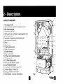
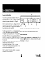
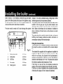
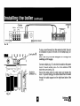
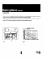
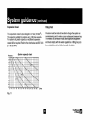
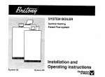
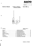
SYSTEM PLUS BOILER
Heating boiler compatible
with indirect cylinder
Faned Flue system
Installation and
Operating instructions
System
plus 40
System
plus 60
=~e~~~
v
u
These instructions are suitable for the following boilers :
BRITONY System plus 40
BRITONY System plus 60
CUSTOMER CARE
Chaffoteaux et Maury Ltd , as a leading manufacturer of domestic and commerctal water heating appliances, is committed to providing high quality products and a
high qualrty after sales service If it is necessary to contact an engineer, then telephone your local Chaffoteaux Service Centre The number can be obtained from
the leaflet enclosed in the customer care pack with your boiler or by telephoning the Chaffoteaux Customer Services Department at Telford.
Advrce on installatron or servicing can also be obtained by contacting the Chaffoteaux Customer Services Department at Telford
CUSTOMER SERVICES DEPARTMENT
Tel 01952 222288
Fax 01952260915
GUARANTEE
The manuiacturer’s guarantee IS for 12 months from the date of purchase. The guarantee is voidable if the appliance is not installed in accordance with the
recommendations made herem or in a manner not approved by the manufacturer To assist us in providing you with an efficient after sales service, please return the
guarantee regtstratron card enclosed with the boiler without delay
STATUTORY REQUIREMENTS
The installation of this appltance must be carried out by a
Safety (Installatton and Use) Regulations
Registered
or other competent person and in accordance
requirements of the Gas
In addition, the installation must also comply with the current byelaws of Local Water Undertakings, Building Regulations, IEE Wiring Regulations, Local Authority
Building Standards (Scotland) Regulations and the Safety Document 635 The Electricity at work Regulation.
It should also be carried out in accordance with current editions of the following British Standards Codes of practice: BS 6891, BS 5440 parts 1 and 2, BS 5449 part
1. BS 7593, BS 6798, BS 5546, BS 4814, BS 7074 part 1 and 2, BS 7671 and BG DM2
If there IS a possibility of the incommg mains water pressure exceedtng IO bar then a suitable pressure limiting valve must be fitted
Precauttons. During servicing, keep the dust generation to a minimum and avoid inhaling any dust and contact with the skin and eyes. Normal handling and use will
not present any dtscomfort, although some people with a history of skin complatnts may be susceptible to irritation. When disposing of the lining, ensure that it is
securely wrapped and wash hands after contact
Page
Page
CUSTOMER CARE ...............................................
Guarantee.. ............................................................
Statutory Requirements.. ......................................
Contents ................................................................
INTRODUCTION ...................................................
DESCRIPTION ......................................................
Location of components.. .......................................
TECHNICAL DATA.. ..............................................
DIMENSIONS.. ......................................................
OPERATION.. ........................................................
Domestic Hot Water Mode.. ...................................
Central Heating Mode.. ..........................................
INSTALLATION REQUIREMENTS.. .....................
Location .................................................................
Flue.. ......................................................................
Ventilation ..............................................................
Gas Supply ............................................................
Electrical Supply ....................................................
INSTALLING THE BOILER ...................................
Installation.. ............................................................
Fitting the horizontal flue.. ......................................
Making the electrical connections.. ........................
COMMISSIONING AND TESTING ........................
Pre-commissioning ................................................
Domestic Hot Water.. .............................................
Central Heating.. ....................................................
Lighting the boiler ..................................................
Post Commissioning.. ............................................
Handing over to the Householder.. ........................
SYSTEM GUIDANCE.. ..........................................
Showers .................................................................
Flushing and Water Treatment ..............................
System Controls ....................................................
Bypass and pump.. ................................................
Expansion Vessel ..................................................
Filling Point ............................................................
USER’S INSTRUCTIONS.. ....................................
Control panel .........................................................
Isolating taps.. ........................................................
Switching on ..........................................................
Hot water ...............................................................
Heating and hot water.. ..........................................
Turn off the boiler.. .................................................
3
3
3
4
5
6
6
8
10
12
12
12
14
14
14
15
15
15
16
16
17
19
q.
21
24
21
21
21
22
22
23
23
23
23
24
25
25
26
26
26
27
27
27
27
chaffot-v
M-u
The BRITONY SYSTEM PLUS is a fully automatic, wall mounted, low water content boiler. It is a room sealed, fan
assisted, balanced flued appliance . The appliance includes a diverter valve and so can provide central heating
and hot water flow for an indirect cylinder.
It has electronic ignition and is suitable for use with all modern electrical control systems. The boiler is designed for
sealed systems only and a circulating pump, expansion vessel together with a pressure gauge and safety valve
are included within the boiler.
The standard horizontal flue kit is suitable for lengths 300 mm minimum to 680 mm maximum and includes an
elbow adapter that can be rotated through 360”. The horizontal flue can be extended (refer to Flue Installation
Instructions), 45” and 90” flue bends are also available as accessories.
The BRITONY SYSTEM PLUS is also suitable for concentric vertical and twin pipe flueing. Adapters and
accessories are available.
The boiler is packed in three cartons:
1. the boiler,
2. the flue assembly and the pre installation kit,
3. additional accessories kit.
Location
of components
1. Air pressure switch
2. Steel chassis complete with expansion vessel
3. Main heat exchanger
4. Combustion chamber
5. Multi- gas burner assembly comprising ignition and
ionisation electrodes
6. Automatic air separator and automatic vent
7. Heating circuit flow switch
8. Pump
9. Electrical box
11. Overheat thermostat
12. Gas valve assembly
13. Sealed chamber
14. Flue hood with fan
16. Primary circuit control thermistor
17. Three way valve
18. CH Flow isolating valve
19. Three position Selector switch
20. User’s instruction panel.
21. Heating flow temperature adjustment
22. Green indicator - Power ON
23. Orange indicator - Burner ON
24. Red indicator - Lock out /flame failure
1
-
4
- 5
11
9-
Fig.
-8
33
25 Reset button
26. Pressure gauge
27. Gas service tap
28. Hot water flow isolating valve
29. CH Return isolating valve
30.
32.
33.
34.
Pressure relief valve
By pass
By pass adjustment screw
Location of central heating filter
BRITONY SYSTEM PLUS type
Appliance
category . .. ... .. . .. . . .. .. . .. .
40
Cat II 2H 3+ Cat II 2H 3,
Heat input C/H & DHW
Maximum in kW .~....~.-........
Maximum in Btulh . ..._............
13.41
45764
Heat output C/H & DHW
Maximum in kW . . .. . . .. . . . . .. . .. . . .
Maximum in Btu/h .. . .. . . .. . . . .. . . .
12
40952
C/H circuit pressures
Min operating in bar
in lb/in*
Max operating in bar
in lb/in’
60
0.7
10
2.5
36.3
BRITONY SYSTEM PLUS type
40
60
Natural gas G20
20.22
69005
Gas rate
Maximum in ma/h ...................
Maximum in ftVh ....................
1.42
50
2.14
76
18
61428
inlet pressure
Nominal in mbar....................
Nominal in in wg.. ..................
20
8
20
8
0.7
IO
2.5
36.3
Burner pressure
Nominal in mbar....................
Nominal in in wg ....................
Burner injector diameter
Natural gas G20 in mm ........
2.9
1.2
1.18
6.7
2.7
1.23
PROPANE L.P.G. G31
Compartment
ventilation
is not required
Gas rate
Maximum in kg/h ...................
Maximum in ftVh.. ..................
1.03
2.27
1.55
3.42
Inlet pressure
Nominal in mbar ....................
Nominal in in wg.. ..................
37
14.8
37
14.8
Burner pressure
Nominal in mbar....................
Nominal in in wg.. ..................
9.2
3.7
21.0
8.4
BRITONY SYSTEM PLUS type
40
60
BUTANE L.P.G. G30
Gas rate
Maximum in kg/h.. .................
Maximum in Lb&h.. ...............
1.05
2.32
1.58
3.48
Inlet pressure
Nominal in mbar . . .. .. . . .. . .. .. . .. . .
Nominal in in wg . . . . .. . . .. . .. .. . . .. .
28
11.2
28
11.2
Burner pressure
Nominal in mbar . . . . . .. . .. . .. . .. . .. .
Nominal in in wg . . . . . .. . .. . . . . .. . .. .
Burner injector diameter
LPG G30 and G31 in mm
Compartment ventilation
..
0.70
not
BRITONY SYSTEM PLUS type
40
60
Safety discharge
inbar..
.................
in lb/in* ..................
3
43.5
3
43.5
Expansion vessel
Pre-charge pressure in bar .
Pre-charge pressure in IbAn*
Net capacity at 3 bar in liter
0.7
9.4
5.44
0.7
9.4
5.44
Adjustable by-pass
Minimum flow rate
Minimum flow rate
Maximum flow rate
Maximum flow rate
100
0.36
700
2.56
100
0.36
700
2.56
230 v
150 w
IP 44
2A
1.25 A
24 v
50Hz
15ow
IP 44
2A
1.25A
24v
in I/h . . .
in gal/min
in I/h . . .
in gal/min
0.70
required
Electrical characteristics
Supply . . . . . . . . . . .
Consumption
,,,..
Protection . . . . . . . .
Fuse no1 . . . . . . . . .
Fuse no2 . . . . . . . . .
External controls . .
.......
... ....
.......
.......
.......
.......
Weights
With packaging :
- BRITONY SYSTEM PLUS 40 :
- BRITONY SYSTEM PLUS 60 :
43.2 kg
43.2 kg
Outer case dimensions :
-Width
440 (minimum space required 450)
- Height
850
- Depth
380
6
Without packaging :
- BRITONY SYSTEM PLUS 40 :
- BRITONY SYSTEM PLUS 60 :
41.2 kg
41.2 kg
Lift weight :
- BRITONY SYSTEM PLUS 40 :
- BRITONY SYSTEM PLUS 60 :
35.2 kg
35.2 kg
Tails diameter
I
Safety valve outlet
015mm
J
Heating flow
022mm
K
H.W. flow
022mm
L
Gas supply
022mm
N
Heating return
022mm
:
cent& line
All dimensions in mm
Fig. 4
Minimum clearances
:
- Both sides
5mm
- Above casing
170 mm
- Below casing
200 mm
- Front ( for servicing)
500 mm
- Front (in operation)
5 mm
TYPE Cl2 or C42
Fig. 5
Dimensions in mm
The boiler is suitable for the 3 flue types :
l typeC 12orC42
l type C 22
l tvoeC32xxorC32xv
TYPE C32 xx
TYPE C32 xy
Domestic
25
Hot Water Mode
To be able to supply hot water, the selector switch (19 fig.
6) must be in either in ,C or ‘1111
,i position. This will be
confirmed by the green indicator light 0 (22 fig. 6).
When the cylinder thermostat is calling for heat, it
switches the 3 way valve (17 fig. 7) to hot water position.
Then the hot water from the primary circuit is diverted
through the cylinder coil to heat DHW.
The first stage solenoid (12a fig. 7) and safety solenoid
(12~ fig. 7) open together to allow gas to the burner.
The ignition sequence begins and a continuous high
speed spark ignites the gas. As soon as a flame is
detected the orange indicator bulb (4 (23 fig. 6) will light
and the second stage solenoid (12b fig. 7) opens to allow
the full gas rate.
If a flame is not detected, after 8 seconds, the security
solenoid closes and shuts off the gas.
The red lockout indicator bulb & (24 fig. 6) will light.
The hot water flow temperature is controlled by the
primary circuit control thermistor (16 fig. 7).
When the cylinder thermostat is satisfied, the burner is
extinguished and the pump stops.
Fig. 6
‘20
The boiler will now stay in the hot water mode for three minutes.
Priority will be given to a demand for reheating the cylinder.
Central Heating Mode
To be able to supply central heating, the selector switch (19 fig. 6)
must be in ‘1111,i position. This will be confirmed by the green
indicator light 0 (22 fig. 6)
When there is a demand for heating (either from the room
thermostat
or the external programmer)
and the boiler
temperature control is calling for heat. The pump starts and at a
flow rate of 4 Itrlmin the central heating flow switch operates
allowing the ignition sequence to begin. The first stage solenoid
(12a fig. 7) and safety solenoid (12~ fig. 7) open together to
allow gas to the burner. The ignition sequence begins and a
continuous high speed spark ignites the gas. As soon as a
flame is detected the orange indicator bulb 4 (23 fig. 6) will
light. After 45 seconds the second stage solenoid (12b fig. 7)
opens to allow the full gas rate. If a flame is not detected, after 8
seconds, the security solenoid closes and shuts off the gas. The
red lockout indicator bulb 0 (24 fig. 6) will light.
The central heating flow temperature is controlled by the central
heating control thermistor (16 fig. 7). The boiler has been
designed to minimise cycling and will not attempt to relight for at
least 3 minutes after the boiler thermostat has been satisfied
(this MTAC delay), can be set to 30 seconds if required, see
maintenance and service guide). When the room thermostat is
satisfied the burner will switch off and the pump will remain
running for a further 3 minutes.
NB
It is possible to override the TAC delay by pressing the RESET
button (25 fig. 6).
I
Location
The boiler can be installed on any suitable internal wall.
Provision must be made to allow the correct routing of the
flue and siting of the terminal to allow the safe and efficient
removal of the flue products. The appliance may be
installed in any room, although reference must be made to
the IEE regulations if it contains a bath or shower. A
compa~ment or cupboard may be used provided that it has
been purpose-built or modified for the purpose. It is not
necessary to provide permanent ventilation for cooling
purposes. Detailed recommendations are given in BS 5440
pt 2. If it is proposed that it is installed in a timber framed
building then reference must be made to British Gas
Document DM2, or advice sought from CORGI.
Flue
The boiler must be installed so that the flue terminal is
exposed to the free passage of external air at all times. It
must not be allowed to discharge into another room or
space such as an outhouse or closed lean-to. The
minimum acceptable clearances are shown below:
- A Directly below an opening, window, etc
- B Below gutters soils pipes or drain pipes
- C Below eaves
- D Below balconies or car port roof
- E From a vertical drain pipe or soil pipe
300 mm
75 mm
200mm
200 mm
75 mm
300 mm
F From an internal or external corner
300 mm
G Above ground roof or balcony level
600 mm
H From a surface facing the terminal
600 mm
I From another terminal facing the terminal
J From an opening into the dwelling when
1200 mm
under a car port
1500 mm
- K Vertically from a terminal on the same wall
- L Horizontally from a terminal on the same wall 300 mm
- M fixed by the flat roof ubbink rolux 4GM flue terminal
- N fixed by a pithed roof ubbink rolux 4GM flue terminal
-
--
-
It may be necessary to protect the terminal with a guard if it is
accessible and could be damaged. Reference should be made to
the Building Regulations for guidance. Suitable guards may be
obtained from the following maufacturer:
Quinnel Barret & Quinnel Wireworks
Old Kent Road
London SE15 1NL
Tel: 0171 639 1357
Ventilation
The room in which the boiler is installed does not require specific
ventilation. IF IT IS INSTALLED IN A CUPBOARD OR
COMPARTMENT
PERMANENT VENTILATION
IS NOT
REQUIRED FOR COOLING PURPOSES. If vents are installed,
they must communicate with the same room or be on the same
wall to outside air.
Gas Supply
The gas installation and soundness testing must be in
accordance with the requirements of BS 6891.The boiler
requires a 22 mm supply. Ensure that the pipe size is
adequate for the demand including other gas appliances on
the same supply.
Electrical
Supply
The appliance requires an earthed 230V - 50 Hz supply and
must be in accordance with current I.E.E. It must also be
possible to be able to completely isolate the appliance
electrically. Connection should be via a 3 amp fused doublepole isolating switch with contact separation of at least 3 mm
on both poles. Alternatively, a fused 3 Amp. 3 pin plug and
unswitched socket may be used, provided it is not used in a
room containing a bath or shower. It should only supply the
appliance.
Please check that you are familiar with the installation
requirements before commencing work.(section 6)
Installation
The installation
kit included with the flue components
comprise following items :
- Hanging bracket
- A paper template (showing the dimensions of the boiler with
5 mm side clearances,
fitting
instructions
and
commissioning instructions)
- Connection tails
- Screws and wall plugs
- Connection washers
- Pre-piping jig
- Installation manual
Also required is the additional accessories kit r-r” 1014574
contain 15 to 22 mm bush and tail.
Drill and plug the wall and secure the hanging bracket using
the screws provided (refer to the paper template drawings).
Remove the boiler from its packaging as shown in fig. 13 and
remove the outer case as shown in fig.14. Place the boiler on
the wall on the hanging bracket after removing the preinstallation jig.
If required, there is space for all piping to pass behind the
Fig. 13
Method of positionning the boiler on the wall.
The paper template can be used to ensure the correct
positioning
of kitchen cabinets etc. It also details the
commissioning instructions.
The paper template has to be fixed to the wall and used to fix
the position of the hanging bracket, the centre for the flue hole
and, if required, the fixings for the pre-piping jig.
Fig. 14
boiler. Using fig. 15 for reference, connect the gas and water
pipes to the valves located at the base of the appliance using
the tails provided. There is a 190 mm space between the
valves and the wall to make these connections.
Provision
must be made to fill and recharge
the system
Fitting the Horizontal Flue
The instructions for the elevated horizontal, vertical and biflux
(twin pipe) flue options are included with the relevant adapter
kits,
The standard flue supplied with the appliance is suitable for
lengths from 300 mm minimum to 610 mm maximum. This
means for rear flueing, the standard kit will accommodate a
maximum wall thickness of 490 mm, and for side flueing a
maximum wail thickness of 477 mm. This takes into account
the minimum appliance side clearances of 5 mm.
If the fixing is a rear exit flue, the template provides the
position of the centre for drilling the flue hole with a core drill.
If the flue is a side exit installation then calculate the position
of the hole with a slope of 5 mm / metre to the terminal.
Fig. 15
I
Safety valve outlet
015mm
J
Heating flow
022mm
K
H.W. flow
022mm
L
Gas supply
022mm
N
Heating return
022mm
pressure. This can be achieved using a filling loop or other
methods approved by the local water authority.
The pressure relief should terminate below the boiler over a
tundish or 22 mm pipe (see I fig 15) which should in turn
discharge safely outside the premises. Care should be taken
that it does not terminate over an entrance or window or
where a discharge of heated water could endanger occupants
or passers by.
The system should be carefully checked for leaks, as frequent
refilling could cause premature
system corrosion
or
unnecessary scaling of the heat exchanger.
q
”
chaffoteaux~
e-U
Connecting
the boiler to the system
- Hinge down the electrical box to gain access to the valves
connections. Push in the tabs (P Fig 19) on either side of the
boiler and pivot the box forward.
- Remove the yellow caps from connecting pipes and connect
the boiler to the taps using gaskets provided in the plastic
bag.
Rubber washer “R” for gas connection.
Provision must be maid to reduce as much as possible the
distance A from the cylinder coil return to the boiler and B
should be greater than 200 mm to avoid gravity effects.
Fig 16
I return
mini
heating return
Fig 17
q:
cygggv
U
Making the Electrical
Connections
Hinge down the electrical box to gain access to the
electrical connections. Push in the tabs (P fig 19) on
either side of the boiler and pivot the box forward.
Undo the two retaining screws (A fig 19), lift the cover
and turn over, and remove cable clamp (see fig. 19a).
Connect the live and neutral wires to the multipin plug
<CDS>
(fig 20) of the PCB -Ea, leaving sufficient earth wire
to connect to the earthing point. (B fig 21)
Note: The connections should be made so that should
the lead be pulled from its anchorage, the current
carrying wires become taut before the earth wire.
Fig. 19
Fig. 19a
-
Earth pillar
Socket for
connector
ALL
Fig. 21
B
C
--
If using a room thermostat or other external control, they can
be connected in place of the link on the multipin plug -Ct>
(fig 20)
Note: Use only controls
designed
for voltage free
switching or 24V supply.
Connect multipin plug c<Cbb
onto into the socket on the power
board. Connect m&ipin plug <CDS)to the interface PCB
inside the cover (see fig. 20).
Secure the cables using the cable clamp and replace the
cover. To prevent damage, the cables should then be routed
through the cable support on the right hand side of the
chassis.
Pre-commissioning
e
Ensure that the system has been adequately flushed.
Purge gas supply of air and test for soundness.
Carry out final electrical tests to ensure the correct polarity
and earthing continuity.
:.:-*.
DHW
Open the hot flow tap (28 fig. 22).
Check for water soundness.
Central Heating
Open flow and return valves on the boiler.(l8 and 29 fig. 22)
Open the automatic air vent (6 fig. 23)
Fill system and vent radiators.
Set system pressure and remove filling loop.
Check for leaks.
Manually check pump is free to turn.
Switch on electrical supply.
Turn selector switch (19 fig. 23) to heating and hot water
position ‘1111
Z .
Allow pump to run for several minutes.
Isolate electrical supply.
Drain boiler and check water filter (34 fig. 2) for installation
debris.
Replace filter and recharge system.
Fig. 22
Lighting the Boiler
Connect gas pressure gauge to test point ( 43 fig. 23).
Turn on the gas supply and boiler gas tap ( 27 fig. 22).
Ensure electrical supply is on.
Ensure all external controls are calling for heat.
Check the operation of the boiler controls and safety devices
(see separate servicing leaflet for details).
Re-flush the system to remove any dissolved oils and fluxes.
Recharge system pressure and introduce any water treatment
as required.
Post Commissioning
,6
43
Ensure system pressure has been set correctly.
Set the by pass.
Set boiler thermostat and controls.
Set programmer to householder’s requirements.
Set external controls.
Handing Over to the Householder
19
21
Fig. 23
Turn selector switch ( 19 fig. 23) to heating and hot water
position ‘1111
,$
Turn the boiler thermostat to maximum (21 fig. 23).
The boiler will light.
Allow the boiler to heat system.
Check that the inlet gas pressure (working pressure) while the
boiler is operating. (refer to technical data).
Demonstrate
Demonstrate
Explain the
person.
Explain how
the lighting and operation of the boiler.
how to maintain the system pressure.
benefits of annual maintenance by a competent
to register guarantee.
Leave users instructions, installation
documentation with the householder.
manual and all other
System Controls
The boiler is suitable for sealed systems only. The maximum
working pressure for the appliance is 3 bar.
All fittings and pipework connected to the appliance should
be of the same standard.
The boiler is electrically controlled and is suitable for most
modern electronic time and temperature
controls. The
addition of such external controls can be beneficial to the
efficient operation of the system. The boiler connections for
external controls are 230V and so only controls of 230V or
that have voltage free contacts should be used.
Flushing and Water Treatment
Betz Dearborn Ltd
Foundry Lane
Widnes
Cheshire
WA8 8UD
Tel: 0151 424 5351
Fernox Manufacturing
Britannica Works
Clavering
Essex
CBll 4QZ
Tel: 01799 550811
la
chaffotealx~
-4LA
By pass and Pump
The boiler is fitted with a pre-adjusted by pass. Although adjustment is not normally necessary, the by pass can be reset by
turning screw ( D fig. 9 ) anticlockwise to open the by-pass using the chart below for guidance.
If used on a system with thermostatic radiator valves, the flow rate with the thermostatic valves closed should be adjusted to
at least 100 Mhr.The chart below indicates the residual head of the pump available for the system.
Head and flow rate available
m H20 I<- Minimum flow rate
\\v vfy
\p \ \
\
I I’
II
II-II
5
4
3
2
1
0
0
1002003004005006007008009001wo1100
D
Fig. 9
Fig. 10
I/h
Expansion
Vessel
Filling Point
The expansion vessel is pre-charged to 0.7 bar (10 Ib/in2).
The vessel is suitable for systems up to 145 litres capacity.
For systems of greater capacity an additional expansion
vessel will be required. Refer to the chart below and BS 7074
pt 1 or BS 5449.
Pressure ’
System capacity
chart
Litres
Fig. 11
Provision must be made to be able to charge the system on
commissioning and to make up any subsequent pressure loss.
The method of connection must utilise approved equipment
and must comply with the water regulations. A filling loop can
be so installed as to be hidden beneath the boiler.
25
Control panel
19. Three position Selector switch
l = Switched OFF
z = Hot water only
c1
* ‘1111
= Hot water + Central heating
20. User’s instruction panel.
21. ‘III1 Heating flow temperature adjustment
22. 0 Green indicator - Power ON
23. @Orange indicator - Burner ON
24. 0 Red indicator - Lock out /flame failure
25 “RESET” Reset button
26. 0
Pressure gauge
Isolating Taps
18.
27.
28.
29.
CH Flow isolating valve
Gas service tap
Hot water flow isolating valve
CH Return isolating valve
Fig. 25
I
Switching
on
1) Check that the gas service tap is opened at the
gasmeter and main power is on.
2) Check that pressure in central heating system is
above 0.7 bar and below 2.5 bar with the pressure
gauge 0 (26).
3) Open the gas tap (27) by turning from right to left. 0
4) The boiler is now ready to use.
Hot Water
1) Turn selector switch (19) to position * . The green
“power on” indicator 0 will light.
2) The orange “burner on” indicator P will light and the
cylinderwill be heated.
Heating and Hot Water
1) Turn selector switch (19) to position ,C ‘1111.
The
green “power on” indicator 0 will light.
2) If the room thermostat
(if fitted), the boiler
temperature control ‘1111and the clock (if fitted) are all
calling for heat, the orange “burner on” indicator pI will
light and the heating will be on.
When the heating is on, it will be interrupted while the
cylinder is reheated. The boiler will switch back
automatically to heating when the cylinder is hot. This is
normal.
Note: If the boiler has been turned off for some time the
first attempt to light it may result in a lockout 0 . If this
happens press the reset button (25) and the boiler will
light.
To Turn Boiler Off Completely
1) Turn the selector switch (19) to the off positionl
2) Turn the gas tap (27) from left to right “STOP”.
.
Chaffoteaux et Maury are continuously improving their products and therefore reserve the right to change specifications without
prior notice and accepts no liability for any errors or omission in the information contained in this document.
o Chaffoteaux et Maury 1998
Chaffoteaux et Maury Ltd
Trench Lock
Trench
Telford
Shropshire
TFl 4SZ
Tel: 01952 222727
Fax: 01952 243493
ESP 039
January 1999
chaffoteaux~
-4.A