1
GIC
Timers
Time Switches
Counters
Logic Controllers
Supply
Monitoring
Devices
PID Controllers
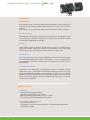
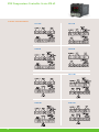
General Industrial Controls Private Limited (GIC), is offering services as a well established
manufacturer and exporter of Process Control and Automation products with unparalleled
sophistication and expertise. We are an ISO 9001:2008, TS 16949 certified company with
International approvals like cULUS. Our products are Eco-friendly, RoHS compliant and CE
certified. Brand "GIC" has been built on this strong foundation over the past three decades
signifying reliability, quality and value for money.
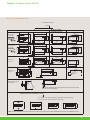
Our product categories include 1) Lighting Automation: Time Switches and Lighting Management
Console 2) Process Control: Mini PLCs, Timers, PID Temperature Controllers 3) Low Voltage
Protection and Switchgear: Voltage Protection, Frequency, Thermistor & Earth Leakage Relays 4)
Instrumentation: Hour Meters, Impulse Counters and 5) Injection Moulded Plastic Components for
various applications.
RoHS Compliant
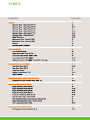
INDEX
CONTENTS
PAGE NOS.
®
TM
2
GIC
www.gicindia.com
TIMERS
Electronic Timer - Series Micon™ 175
Electronic Timer - Series Micon™ 225
Electronic Timer - Series Micon™ 350
Electronic Timer - Series Micon™ 480
Electronic Timer - Series Micon™ 780
Electronic Timer - Series Staircase™
Digital Timer
®
Synchronous Timer - Series EM 1000
Synchronous Timer - Series EM 2000
Glossary
Operating Modes / Functions
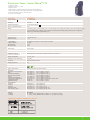
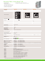
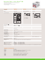
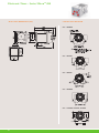
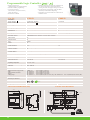
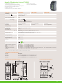
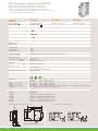
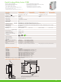
Electronic Timer - Series MiconTM 175
• Compact 17.5mm
• Time range: 0.3s - 30h
• Highly accurate
• Functions: On Delay, One Shot
• Integrated dual voltage selection
• Separate indications for power and relay status
• Low power consumption
Cat. No.
11ODT4
11BDT4
Parameters
Mode
ON Delay
One Shot
Functional Diagram
= Supply
R = Relay
R
R
T
Supply Voltage (
110 VAC / 24 VAC/DC
(Selectable)
- 20% to +10% (of )
50/60 Hz
0.3s to 30h
100 ms (Max.)
)
Supply Variation
Frequency
Timing Ranges
Reset Time
Accuracy:
Setting Accuracy
Repeat Accuracy
Relay Output
Contact Rating
Contact Material
Electrical Life
Switching Frequency
@ rated max load
Utilization Category
T
1 Sec.
110 VAC / 24 VAC/DC
(Selectable)
± 5% of Full scale
± 1%
1 C/O (SPDT)
5A (resistive) @ 240 VAC / 28 VDC
Ag Alloy
1X10⁵
AC - 15
DC - 13
Operating Temperature
Storage Temperature
LED Indication
Enclosure
Dimension (W x H x D) (in mm)
Weight (unpacked)
Mounting
1000 operations/h (Max.)
Rated Voltage (Ue): 120/240 V, Rated Current (Ie): 3.0/1.5 A
Rated Voltage (Ue): 24/125/250 V, Rated Current (Ie): 2.0/0.22/0.1 A
-10°C to +55°C
-20°C to +70°C
Green LED
Power ON, Red LED
Relay ON
Flame Retardant UL94V0
18 X 65 X 90
75 g
Base / DIN rail
Certification
RoHS Compliant
Degree of Protection
EMI/ EMC
Radio Interference Suppression
ESD
Electrical Fast Transients
Surges
Voltage Dips & Interruptions
Environmental
Cold Heat
Dry Heat
Vibration
Repetitive Shock
Non-repetitive shock
IP 20 for Terminals, IP 30 for Enclosure
CISPR 14-1
IEC 61000-4-2
IEC 61000-4-4
IEC 61000-4-5
IEC 61000-4-11
Ed. 5.0 (2005-11) Class A
Ed. 1.2 (2001-04) Level II
Ed. 2.0 (2004-07) Level IV
Ed. 2.0 (2005-11) Level IV
Ed. 2.0 (2004-03) All 7 Levels (AC), IEC 61000-4-29
IEC 60068-2-1
IEC 60068-2-2
IEC 60068-2-6
IEC 60068-2-27
IEC 60068-2-27
Ed. 6.0 (2007-03)
Ed. 5.0 (2007-07)
Ed. 7.0 (2007-12) 5g
Ed. 4.0 (2008-02) 40g, 6ms
Ed. 4.0 (2008-02) 30g, 15ms
Ed. 1.0 (2000-08) All 5 Levels (DC)
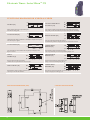
ORDERING INFORMATION
Cat. No.
11ODT4
12ODT4
15ODT4
11ODT8
12ODT8
Description
110 VAC, 24 VAC/DC, On Delay
240 VAC, 24 VAC/DC, On Delay
12 VDC, On Delay
110 VAC, 24 VAC/DC, On Delay Retentive
240 VAC, 24 VAC/DC, On Delay Retentive
11BDT4
12BDT4
15BDT4
110 VAC, 24 VAC/DC, One Shot
240 VAC, 24 VAC/DC, One Shot
12 VDC, One Shot
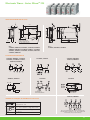
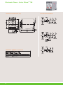
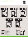
MOUNTING DIMENSION (mm)
CONNECTION DIAGRAM
17.5 (+0.5, -0.0)
A = 58.5 (Without Dust Cover)
A
B
B = 65 (With Dust Cover)
*Note: For terminal torque & terminal capacity please refer page no. 16
4
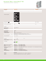
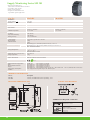
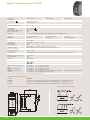
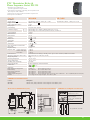
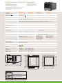
Electronic Timer - Series MiconTM 175
• Compact 17.5mm
• Wide time range: 0.1s - 100h
• Highly accurate
• Multi-function: 10 different functions (Signal & Non Signal based)
• Multi-voltage: Single model suitable for both AC and DC applications
• Separate indications for power and relay status
• Low power consumption
Cat. No.
Supply Voltage (
1CMDT0
)
12 - 240 VAC/DC
Supply Variation
Frequency
- 15% to +10% (of
50/60 Hz
)
Signal Supply Range
As per Supply Voltage (
Power Consumption (Max.)
Modes
2 VA
)
1. On Delay [tn], 2. Cyclic ON/OFF [cnf], 3. Cyclic OFF/ON [cfn], 4. Signal OFF Delay [sf], 5. Signal OFF/ON [sfn],
6. Accumulative Delay on Signal [san], 7. Impulse ON/OFF [inf], 8. Leading Edge Impulse [iL], 9. Trailing Edge
Impulse [it], 10. Leading Edge Bi-stable [sbi]
Timing Ranges
0.1s to 100h
Accuracy:
Setting Accuracy
Repeat Accuracy
Relay Output
Contact Rating
Contact Material
Electrical Life
Mechanical Life
± 5% of Full scale
± 1%
1 C/O (SPDT)
8A (resistive) @ 240 VAC / 5A (resistive) @ 24 VDC
Ag Alloy
1X10⁵
1X10⁷
LED Indication
Green LED
Power ON, Yellow LED
100 ms (Max.)
Initiate Time
Relay ON
100 ms (Max.)
Reset Time
Operating Temperature
Storage Temperature
Rated Voltage (Ue): 120/240 V, Rated Current (Ie): 3.0/1.5 A
Rated Voltage (Ue): 24/125/250 V, Rated Current (Ie): 2.0/0.22/0.1 A
-15°C to +60°C
-20°C to +80°C
Humidity (Non Condensing)
95% (Rh)
Enclosure
Dimension (W x H x D) (in mm)
Weight (unpacked)
Mounting
Flame Retardant UL94-V0
18 X 60 X 85
70 g
Base / DIN rail
Utilization Category
AC - 15
DC - 13
Certification
Degree of Protection
EMI/ EMC
Harmonic Current Emissions
ESD
Radiated Susceptibility
Electrical Fast Transients
Surges
Conducted Susceptibility
Voltage Dips & Interruptions
Conducted Emission
Radiated Emission
Environmental
Cold Heat
Dry Heat
Vibration
Repetitive Shock
Non-repetitive shock
RoHS Compliant
IP 20 for Terminals, IP 40 for Enclosure
IEC 61000-3-2
IEC 61000-4-2
IEC 61000-4-3
IEC 61000-4-4
IEC 61000-4-5
IEC 61000-4-6
IEC 61000-4-11
CISPR 14-1
CISPR 14-1
Ed. 3.0 (2005-11) Class A
Ed. 1.2 (2001-04) Level II
Ed. 3.0 (2006-02) Level IV
Ed. 2.0 (2004-07) Level IV
Ed. 2.0 (2005-11) Level III
Ed. 2,2 (2006-05) Level III
Ed. 2.0 (2004-03) Performance Criteria B/A
Ed. 5.0 (2005-11) Class A
Ed. 5.0 (2005-11) Class A
IEC 60068-2-1
IEC 60068-2-2
IEC 60068-2-6
IEC 60068-2-27
IEC 60068-2-27
Ed. 6.0 (2007-03)
Ed. 5.0 (2007-07)
Ed. 7.0 (2007-12) 5g
Ed. 4.0 (2008-02) 40g, 6ms
Ed. 4.0 (2008-02) 30g, 15ms
ORDERING INFORMATION
Cat. No.
1CMDT0
1CMDTB
Description
12 - 240 V AC/DC, Multifunction (10 Modes), 1 C/O, Dark Grey Casing
12 - 240 V AC/DC, Multifunction (10 Modes), 1 C/O, Light Grey Casing
TERMINAL TORQUE & TERMINAL CAPACITY
5
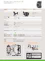
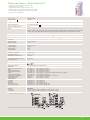
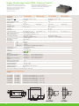
Electronic Timer - Series MiconTM 175
FUNCTIONAL DIAGRAMS FOR 1CMDT0 & 1CMDTB
U
U
ACCUMULATIVE DELAY
ON SIGNAL [san]
ON DELAY [tn]
R
T
R
T
U
TON
IMPULSE ON/OFF [inf]
R
TOFF
TOFF
This function is quite similar to the function ‘1’ but initially the relay(R) is ON for period
T-ON after the power is applied.
LEADING EDGE
IMPULSE2 [il]
TOFF
TON
T
B1
TON
T-ON and T-OFF can be same or different. The relay(R) keeps on changing its status
till power is removed.
R
U
TRAILING EDGE
IMPULSE1 [it]
B1
R
T
LEADING EDGE
BISTABLE [sbi]
B1
When switch B1 is closed or opened for preset time ,T, the
relay changes its state after time duration T.
MOUNTING DIMENSION (mm)
T
When B1 is opened, R energizes and de-energizes when
timing is over. If B1 is closed during timing R resets.
U
T
B1
R
T
R energizes when switch B1 is closed. Timing
commences after S is opened and then the relay de-energizes.
R
T
When switch B1 is closed, and remains closed output
relay energizes until timing is over. If B1 is opened during timing, R resets.
U
6
T
T
T
R energizes for the timing period when B1 is opened or
closed. When timing commences, changing state of B1 does not affect R but resets timer.
U
TOFF
R
SIGNAL OFF/ON [sfn]
B1
R
U
SIGNAL
OFF DELAY [sf]
T
U
TON
CYCLIC OFF/ON [cfn]
t1
t2
T+t1+t2
Time commences as supply is present and switch B1 is open. Closing switch B1 pauses
timing. Timing resumes when switch B1 is opened again. R energizes at the end of timing.
Timing commences when supply is present.R energizes
at the end of the timing period.
CYCLIC ON/OFF [cnf]
B1
U
B1
R
Relay energizes when B1 is closed. Further every time B1 is closed,
R keeps on changing its status till supply is on
CONNECTION DIAGRAM
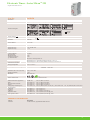
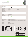
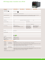
Electronic Timer - Series MiconTM 225
• LED indications for runtime and relay status
• Excellent Noise Immunity to the latest IEC standards
• World-Class design
• Compact 22.5mm
• Single and Multi-function
(Non-Signal and Signal based) timers
• Multi-voltage: Single model suitable
for both AC and DC applications
• Flush knobs for better security
Cat. No.
2A5DT5
Parameters
Mode
Multi-function Multi range
A.
ON
DELAY
2AJDT0
2ASDT0
Asymmetrical ON-OFF / OFF-ON
Star-Delta
25-28
15-18
Ts
25-28 Ts
B.
INTERVAL 15-18
Ts = Set Time
Functional Diagram
Supply Voltage ( )
Supply Variation
Frequency
Power Consumption (Max.)
Timing Ranges
Pause Time (P)
Reset Time
Accuracy
Setting Accuracy
Repeat Accuracy
Relay Output
Contact Rating
Contact Material
Electrical Life
Mechanical Life
Switching Frequency
@ rated max load
Utilization Category
Ts
A
C.
CYCLIC
ON/OFF
25-28
15-18
D.
CYCLIC
OFF/ON
25-28
15-18 Ts
Ts
25-28
15-18
1s
E.
ONE
SHOT
Ts
Off
On
B
On Off
Operating Temperature
Storage Temperature
Humidity (Non Condensing)
LED Indication
Enclosure
Dimension (W x H x D) (in mm)
Weight (unpacked)
Mounting
P
Ts = T x t
P = Pause Time
T2 x t2 = OFF Time
Ts
Ts
25-28
T1 x t1 = ON Time
Ts = T x t
24 - 240 VAC/DC
- 20% to +10% (of
50/60 Hz
4 VA
0.1s to 10h
N. A.
Max. 200 ms
)
7 VA
0.3s to 120s
60ms, 90ms, 120ms, 150ms
± 5% of Full scale
+ 1%
2 C/O (DPDT)
1 C/O (SPDT)
5A @ 240 VAC / 28 VDC (Resistive)
Ag Alloy
1x1057
1x10
AC - 15
DC - 13
15-18
15-18
Electrical : 1800 Operations / h
Rated Voltage (Ue): 120/240 V, Rated Current (Ie): 3.0/1.5 A
Rated Voltage (Ue): 24/125/250 V, Rated Current (Ie): 2.0/0.22/0.1 A
-15°C to +60°C
-20°C to +80°C
95% (Rh)
Green LED
Power ON, Red LED
Relay ON
Flame Retardant UL94-V0
22.5 X 75 X 100.5
130 g
Base / DIN rail
Star - 1 'NO', Delta - 1 'NO'
Red 1-
ON, Red 2-
ON
Certification
RoHS Compliant
Degree of Protection
EMI/ EMC
Radio Interference Suppression
ESD
Electrical Fast Transients
Surges
Voltage Dips & Interruptions
Environmental
Cold Heat
Dry Heat
Vibration
Repetitive Shock
Non-repetitive shock
IP 20 for Terminals, IP 40 for Enclosure
CISPR 14-1
IEC 61000-4-2
IEC 61000-4-4
IEC 61000-4-5
IEC 61000-4-11
Ed. 5.0 (2005-11) Class A
Ed. 1.2 (2001-04) Level II
Ed. 2.0 (2004-07) Level IV
Ed. 2.0 (2005-11) Level IV
Ed. 2.0 (2004-03) All 7 Levels (AC), IEC 61000-4-29
IEC 60068-2-1
IEC 60068-2-2
IEC 60068-2-6
IEC 60068-2-27
IEC 60068-2-27
Ed. 6.0 (2007-03)
Ed. 5.0 (2007-07)
Ed. 7.0 (2007-12) 5g
Ed. 4.0 (2008-02) 40g, 6ms
Ed. 4.0 (2008-02) 30g, 15ms
Ed. 1.0 (2000-08) All 5 Levels (DC)
ORDERING INFORMATION
Cat. No.
2A5DT5
2B5DT5
273DT5
2AODT5
29ODT5
Description
24-240 VAC/DC, Multi-function, 2 C/O
240-415 VAC, Multi-function, 2 C/O
240 VAC, Multi-function (On Delay, Interval, Cyclic), 2 C/O
24-240 VAC/DC, On Delay, 2 C/O
9-32 VDC, On Delay, 2 C/O
2ASDT0*
2ASDT1
2BSDT0*
2BSDT1
24-240 VAC/DC, Star-Delta, 1 NO (Star) + 1 NO (Delta)
24-240 VAC/DC, Star-Delta, 1 NO (Star) + 1 NO (Delta)
240-415 VAC, Star-Delta, 1 NO (Star) + 1 NO (Delta)
240-415 VAC, Star-Delta, 1 NO (Star) + 1 NO (Delta)
2AJDT0*
2AJDT1
2AADT5
25ADT5
24-240 VAC/DC, Asymmetric ON/OFF, OFF/ON, 1 C/O
24-240 VAC/DC, Asymmetric ON/OFF, OFF/ON, 1 C/O
24-240 VAC/DC, Asymmetric ON/OFF, 2 C/O
12 VDC, Asymmetric ON/OFF, 2 C/O
*Note: Product with test voltage between input and output at 1.5 kV
7
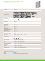
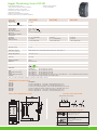
Electronic Timer - Series MiconTM 225
• Multi-function Timer with 1 Instant + 1 Delayed contact
Cat. No.
2A6DT6
Parameters
Mode
ON Delay, Interval, Cyclic ON/OFF, Cyclic OFF/ON, One Shot, ON Delay with 1 Instant + 1 Delayed Contact
A.
ON
DELAY
2B6DT6
25-28
15-18
Ts
25-28 Ts
B.
INTERVAL 15-18
Functional Diagram
Ts
C.
CYCLIC
ON/OFF
25-28
15-18
D.
CYCLIC
OFF/ON
25-28
15-18 Ts
Ts
25-28
15-18
1s
E.
ONE
SHOT
F.
ON DELAY 25-28
(1 INSTANT
+
15-18
1 DELAY)
Ts
Ts
Ts
Ts = T x t
Supply Voltage ( )
Supply Variation
Frequency
Power Consumption (Max.)
Timing Ranges
Reset Time
Accuracy
Setting Accuracy
Repeat Accuracy
24 - 240 VAC/DC
- 20% to +10% (of
50/60 Hz
4 VA
0.1s to 10h
Max. 200 ms
240 - 415 VAC
)
7 VA
Relay Output
± 5% of Full scale
+ 1%
2 Delayed C/O (for 1st 5 modes), 1 Instant + 1 Delayed (for 6th mode)
Contact Rating
Contact Material
Electrical Life
Mechanical Life
Switching Frequency
@ rated max load
5A @ 240 VAC / 28 VDC (Resistive)
Ag Alloy
1x10 5
1x10 7
Electrical : 1800 Operations / h
Operating Temperature
Storage Temperature
Rated Voltage (Ue): 120/240 V, Rated Current (Ie): 3.0/1.5 A
Rated Voltage (Ue): 24/125/250 V, Rated Current (Ie): 2.0/0.22/0.1 A
-15° C to +60° C
-20° C to +80° C
Humidity (Non Condensing)
95% (Rh)
LED Indication
Enclosure
Dimension (W x H x D) (in mm)
Weight (unpacked)
Mounting
Green LED
Power ON
Flame Retardant UL94-V0
22.5 X 75 X 100.5
130 g
Base / DIN rail
Utilization Category
AC - 15
DC - 13
Red LED
Relay ON
Certification
RoHS Compliant
Degree of Protection
EMI/ EMC
Radio Interference Suppression
ESD
Electrical Fast Transients
Surges
Voltage Dips & Interruptions
Environmental
Cold Heat
Dry Heat
Vibration
Repetitive Shock
Non-repetitive shock
IP 20 for Terminals, IP 40 for Enclosure
CISPR 14-1
IEC 61000-4-2
IEC 61000-4-4
IEC 61000-4-5
IEC 61000-4-11
Ed. 5.0 (2005-11) Class A
Ed. 1.2 (2001-04) Level II
Ed. 2.0 (2004-07) Level IV
Ed. 2.0 (2005-11) Level IV
Ed. 2.0 (2004-03) All 7 Levels (AC), IEC 61000-4-29
IEC 60068-2-1
IEC 60068-2-2
IEC 60068-2-6
IEC 60068-2-27
IEC 60068-2-27
Ed. 6.0 (2007-03)
Ed. 5.0 (2007-07)
Ed. 7.0 (2007-12) Level 5g
Ed. 4.0 (2008-02) Level 40g, 6ms
Ed. 4.0 (2008-02) Level 30g, 15ms
ORDERING INFORMATION
Cat. No.
2A6DT6
2B6DT6
8
Description
24-240 VAC/DC, Multi-function, 2 C/O or 1 Instant + 1 Delayed C/O
240-415 VAC, Multi-function, 2 C/O or 1 Instant + 1 Delayed C/O
Ed. 1.0 (2000-08) All 5 Levels (DC)
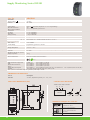
Electronic Timer - Series MiconTM 225
• Signal based Multi-function
Cat. No.
2ANDT0
Parameters
Mode
Signal ON Delay, Accumulative ON Delay, Signal OFF Delay, Signal OFF/ON Delay, Leading Edge Impulse 1, ON Delay, Interval
Functional Diagram
= Supply
S = Signal
Supply Voltage ( )
Supply Variation
Frequency
Power Consumption (Max.)
Timing Ranges
Reset Time
Accuracy
Setting Accuracy
Repeat Accuracy
24 - 240 VAC/DC
- 20% to +10% (of
50/60 Hz
4 VA
0.1s to 10h
Max. 200 ms
)
Relay Output
± 5% of Full scale
+ 1%
1 C/O (SPDT)
Contact Rating
Contact Material
Electrical Life
Mechanical Life
Switching Frequency
@ rated max load
5A @ 240 VAC / 28 VDC (Resistive)
Ag Alloy
1x10 5
1x10 7
Electrical : 1800 Operations / h
AC - 15
DC - 13
Operating Temperature
Storage Temperature
Rated Voltage (Ue): 120/240 V, Rated Current (Ie): 3.0/1.5 A
Rated Voltage (Ue): 24/125/250 V, Rated Current (Ie): 2.0/0.22/0.1 A
-15° C to +60° C
-20° C to +80° C
Humidity (Non Condensing)
95% (Rh)
LED Indication
Enclosure
Dimension (W x H x D) (in mm)
Weight (unpacked)
Mounting
Green LED
Power ON
Flame Retardant UL94-V0
22.5 X 75 X 100.5
130 g
Base / DIN rail
Utilization Category
Red LED
Relay ON
Certification
RoHS Compliant
Degree of Protection
EMI/ EMC
Radio Interference Suppression
ESD
Electrical Fast Transients
Surges
Voltage Dips & Interruptions
Environmental
Cold Heat
Dry Heat
Vibration
Repetitive Shock
Non-repetitive shock
IP 20 for Terminals, IP 40 for Enclosure
CISPR 14-1
IEC 61000-4-2
IEC 61000-4-4
IEC 61000-4-5
IEC 61000-4-11
Ed. 5.0 (2005-11) Class A
Ed. 1.2 (2001-04) Level II
Ed. 2.0 (2004-07) Level IV
Ed. 2.0 (2005-11) Level IV
Ed. 2.0 (2004-03) All 7 Levels (AC), IEC 61000-4-29
IEC 60068-2-1
IEC 60068-2-2
IEC 60068-2-6
IEC 60068-2-27
IEC 60068-2-27
Ed. 6.0 (2007-03)
Ed. 5.0 (2007-07)
Ed. 7.0 (2007-12) Level 5g
Ed. 4.0 (2008-02) Level 40g, 6ms
Ed. 4.0 (2008-02) Level 30g, 15ms
Ed. 1.0 (2000-08) All 5 Levels (DC)
ORDERING INFORMATION
Cat. No.
2ANDT0
Description
24-240 VAC/DC, Signal Based Multi-function
9
Electronic Timer - Series MiconTM 225
• Signal based Multi-function with Solid State Output.
Cat. No.
20NDTT
Parameters
Mode
Signal ON Delay, Accumulative ON Delay, Signal OFF Delay, Signal OFF/ON Delay, Leading Edge Impulse 1, ON Delay, Interval
Functional Diagram
= Supply
S = Signal
Supply Voltage ( )
Supply Variation
Frequency
Power Consumption (Max.)
Timing Ranges
Reset Time
Accuracy
Setting Accuracy
Repeat Accuracy
110 - 240 VAC
- 20% to +10% (of
50/60 Hz
3 VA
0.06s to 10h
Max. 100 ms
)
± 5% of Full scale
+ 1%
Solid State Output:
Type
Form
Rated Current
Max. Admissible Current
Leakage Current
Voltage Breaking Capacity
Max. Voltage Drop at Terminals
Minimum Load Current
Electrical Life
Optical Isolation
SPST
1A (AC)
20 A (10ms)
<5 mA
110 - 240 VAC
<= 8 V
20 mA
1 x 10⁶
Operating Temperature
Storage Temperature
-15° C to +60° C
-20° C to +80° C
Humidity (Non Condensing)
95% (Rh)
LED Indication
Enclosure
Dimension (W x H x D) (in mm)
Weight (unpacked)
Mounting
Green LED
Power ON
Flame Retardant UL94-V0
22.5 X 75 X 100.5
107 g
Base / DIN rail
Red LED
Output ON
Certification
RoHS Compliant
Degree of Protection
IP 20 for Terminals, IP 40 for Enclosure
EMI/ EMC
Radio Interference Suppression
ESD
Electrical Fast Transients
Surges
Voltage Dips & Interruptions
CISPR 14-1
IEC 61000-4-2
IEC 61000-4-4
IEC 61000-4-5
IEC 61000-4-11
Ed. 5.0 (2005-11) Class A
Ed. 1.2 (2001-04) Level II
Ed. 2.0 (2004-07) Level IV
Ed. 2.0 (2005-11) Level IV
Ed. 2.0 (2004-03) All 7 Levels (AC), IEC 61000-4-29
Environmental
Cold Heat
Dry Heat
Vibration
Repetitive Shock
Non-repetitive shock
IEC 60068-2-1
IEC 60068-2-2
IEC 60068-2-6
IEC 60068-2-27
IEC 60068-2-27
Ed. 6.0 (2007-03)
Ed. 5.0 (2007-07)
Ed. 7.0 (2007-12) Level 5g
Ed. 4.0 (2008-02) Level 40g, 6ms
Ed. 4.0 (2008-02) Level 30g, 15ms
ORDERING INFORMATION
Cat. No.
20NDTT
20JDTT
10
Description
110-240 VAC, Solid State Signal Based Multi-function
110-240 VAC, Solid State Asymmetrical ON-OFF / OFF-ON
Ed. 1.0 (2000-08) All 5 Levels (DC)
Electronic Timer - Series MiconTM 225
• True OFF delay (Power OFF Delay) upto 600 seconds with 2 C/O.
Cat. No.
23GDT0
Parameters
Mode
True OFF delay (Power OFF delay)
Functional Diagram
Relay
T
T = Set Time
Supply Voltage (
24 - 240 VAC/DC
)
Supply Variation
Power Consumption (Max.)
Frequency
Energizing Time
Timing Range
Accuracy
Setting Accuracy
Repeat Accuracy
Relay Output
Contact Rating
Contact Material
Electrical Life
Mechanical Life
Switching Frequency
@ rated max load
Utilization Category
AC - 15
DC - 13
Operating Temperature
Storage Temperature
-10 to +20% (of
2.5 VA
)
50-60 Hz
1s minimum
0.6s to 600s
± 5% of Full scale
+ 1%
2 C/O (DPDT)
5A @ 240 VAC / 28 VDC (Resistive)
Ag Alloy
1x10 5
1x10 7
Electrical : 1800 Operations / h
Rated Voltage (Ue): 120/240 V, Rated Current (Ie): 3.0/1.5 A
Rated Voltage (Ue): 24/125/250 V, Rated Current (Ie): 2.0/0.22/0.1 A
-15° C to +60° C
-20° C to +70° C
Humidity (Non Condensing)
95% (Rh)
LED Indication
Enclosure
Dimension (W x H x D) (in mm)
Weight (unpacked)
Mounting
Green LED
Power ON
Flame Retardant UL94-V0
22.5 X 75 X 100.5
130 g
Base / DIN rail
Certification
RoHS Compliant
Degree of Protection
IP 20 for Terminals, IP 40 for Enclosure
EMI/ EMC
Radio Interference Suppression
ESD
Electrical Fast Transients
Surges
Voltage Dips & Interruptions
CISPR 14-1
IEC 61000-4-2
IEC 61000-4-4
IEC 61000-4-5
IEC 61000-4-11
Ed. 5.0 (2005-11) Class A
Ed. 1.2 (2001-04) Level II
Ed. 2.0 (2004-07) Level IV
Ed. 2.0 (2005-11) Level IV
Ed. 2.0 (2004-03) All 7 Levels (AC), IEC 61000-4-29
Environmental
Cold Heat
Dry Heat
Vibration
Repetitive Shock
Non-repetitive shock
IEC 60068-2-1
IEC 60068-2-2
IEC 60068-2-6
IEC 60068-2-27
IEC 60068-2-27
Ed. 6.0 (2007-03)
Ed. 5.0 (2007-07)
Ed. 7.0 (2007-12) Level 5g
Ed. 4.0 (2008-02) Level 40g, 6ms
Ed. 4.0 (2008-02) Level 30g, 15ms
Ed. 1.0 (2000-08) All 5 Levels (DC)
ORDERING INFORMATION
Cat. No.
23GDT0
Description
24-240 VAC/DC, True-off Delay (Power Off Delay)
11
Electronic Timer - Series MiconTM 225
• Single phase motor restart control timer with memory time,
under voltage trip and ON delay
Cat. No.
22LDT0
Parameters
Mode
Motor Restart
t > Tm
Functional Diagram
t < = Tm
A1 - A2
STOP
START
Td
15-18
t = Power Fail Time
Supply Voltage ( )
Supply Variation
Frequency
Power Consumption (Max.)
240 VAC
- 20% to +10% (of
50/60 Hz
4 VA
Timing Ranges
Memory Time (Tm): 0.2 to 6s, Delay Time (Td): 0.2 to 60s
Trip Volt: 176 VAC, +/- 6VAC, Hysterisis: 10 VAC max.
Reset Time
Accuracy
Setting Accuracy
Repeat Accuracy
Max. 200 ms
± 5% of Full scale
+ 1%
1 C/O (SPDT)
5A @ 240 VAC / 28 VD C (Resistive)
Ag Alloy
1x10 5
1x10 7
Electrical : 1800 Operations / h
Relay Output
Contact Rating
Contact Material
Electrical Life
Mechanical Life
Switching Frequency
@ rated max load
Utilization Category
)
AC - 15
DC - 13
Operating Temperature
Storage Temperature
Humidity (Non Condensing)
LED Indication
Enclosure
Dimension (W x H x D) (in mm)
Weight (unpacked)
Mounting
Rated Voltage (Ue): 120/240 V, Rated Current (Ie): 3.0/1.5 A
Rated Voltage (Ue): 24/125/250 V, Rated Current (Ie): 2.0/0.22/0.1 A
-15° C to +60° C
-20° C to +80° C
95% (Rh)
Green LED
Power On, Red LED
Relay On
Flame Retardant UL94-V0
22.5 X 75 X 100.5
130 g
Base / DIN rail
Certification
RoHS Compliant
Degree of Protection
IP 20 for Terminals, IP 40 for Enclosure
EMI/ EMC
Radio Interference Suppression
ESD
Electrical Fast Transients
Surges
Voltage Dips & Interruptions
CISPR 14-1
IEC 61000-4-2
IEC 61000-4-4
IEC 61000-4-5
IEC 61000-4-11
Ed. 5.0 (2005-11) Class A
Ed. 1.2 (2001-04) Level II
Ed. 2.0 (2004-07) Level IV
Ed. 2.0 (2005-11) Level IV
Ed. 2.0 (2004-03) All 7 Levels (AC), IEC 61000-4-29
Environmental
Cold Heat
Dry Heat
Vibration
Repetitive Shock
Non-repetitive shock
IEC 60068-2-1
IEC 60068-2-2
IEC 60068-2-6
IEC 60068-2-27
IEC 60068-2-27
Ed. 6.0 (2007-03)
Ed. 5.0 (2007-07)
Ed. 7.0 (2007-12) Level 5g
Ed. 4.0 (2008-02) Level 40g, 6ms
Ed. 4.0 (2008-02) Level 30g, 15ms
ORDERING INFORMATION
Cat. No.
22LDT0
12
Description
240 VAC, Motor Restart Control
Ed. 1.0 (2000-08) All 5 Levels (DC)
Electronic Timer - Series MiconTM 225
MOUNTING DIMENSION (mm)
4.3
100.5
22.5
12.5
35.0
57.0
62.5
75.0
81.0
INSERT SCREW DRIVER
TO RELEASE DIN RAIL CLIP
DIN - RAIL (35mm symmetrical)
For 2A5DT5, 2B5DT5, 2AODT5, 2ASDT0, 2ASDT1,
2BSDT0, 2BSDT1, 2AJDT0, 2AJDT1, 2AADT5,
20JDTT, 20NDTT, 2ANDT0, 23GDT0, 22LDT0
2A6DT6, 2B6DT6
For 273DT5, 29ODT5, 25ADT5
CONNECTION DIAGRAM
2A5DT5, 2B5DT5, 2AADT5,
23GDT0, 2AODT5, 273DT5,
29ODT5, 25ADT5
2AJDT0, 2AJDT1
20JDTT, 20NDTT
2ANDT0
2ASDT0, 2BSDT0,
2ASDT1, 2BSDT1
22LDT0
L
A1 A2
Y1
V
V
B2 Y2
B1
LOAD
S
N
For ON Delay &
Interval Mode Selection
2A6DT6, 2B6DT6
TERMINAL TORQUE & TERMINAL CAPACITY
Ø 3.5
4.0mm
Torque 0.6 N.m (6 Lb. in)
Terminal Screw - M3
1 x 1 - 4 mm2 Solid Wire / Single Wire Ferrule
2 x 0.5 - 2.5 mm2 insulated twin type Ferrule
AWG
1 x 16 to 12
[for 1st 5 modes both the contacts are delayed &
for 6th mode 1st contact (15, 16, 18) is delayed &
2nd contact (25, 26, 28) is Instant]
13
Electronic Timer - Series MiconTM 350
• Selectable ON delay/Retentive ON delay
• Inbuilt instant contact with 2C/O
37EDT7
33EDT7
Cat. No.
36EDT7
Parameters
Mode
ON Delay/Retentive ON Delay (Selectable)
T = Set Time
T = t1 + t2 + t3
tp1, tp2 = Power down
region
Functional Diagram
R
R
t1
T
Supply Voltage ( )
Supply Variation
Frequency
Timing Ranges
Reset Time
Accuracy
Setting Accuracy
Repeat Accuracy
24 VAC/DC
- 20% to +10% (of
t3
tp2
240 VAC
110 VAC
)
50/60 Hz
0.3s to 30h
100 ms (Max.)
± 5% of Full scale
± 1%
1 Instant C/O + 2 Delayed C/O
5A (resistive) @ 240 VAC / 28 VDC
AgCdO
1x10⁵
Relay Output
Contact Rating
Contact Material
Electrical Life
Switching Frequency
@ rated max load
1000 operations/h (Max.)
Operating Temperature
Storage Temperature
-10° C to +55° C
-20° C to +70° C
LED Indication
Green LED
Enclosure
Dimension (W x H x D) (in mm)
Weight (unpacked)
Mounting
Flame Retardant UL94V0
36 X 90 X 67
135 g
Base / DIN rail
Certification
EMI/ EMC
Radio Interference Suppression
ESD
Electrical Fast Transients
Surges
Voltage Dips & Interruptions
t2
tp1
= Supply
R = Relay
Power ON, Red LED
Relay ON
RoHS
RoHS Compliant
CISPR 14-1
IEC 61000-4-2
IEC 61000-4-4
IEC 61000-4-5
IEC 61000-4-11
Ed. 5.0 (2005-11) Class A
Ed. 1.2 (2001-04) Level II
Ed. 2.0 (2004-07) Level IV
Ed. 2.0 (2005-11) Level IV
Ed. 2.0 (2004-03) All 7 Levels (AC), IEC 61000-4-29
Ed. 1.0 (2000-08) All 5 Levels (DC)
ORDERING INFORMATION
Cat. No.
36EDT7
33EDT7
37EDT7
Description
24V AC/DC, ON Delay/Retentive ON Delay
110V AC, ON Delay/Retentive ON Delay
240V AC, ON Delay/Retentive ON Delay
MOUNTING DIMENSION (mm)
CONNECTION DIAGRAM
INSTANT
TERMINAL TORQUE & CAPACITY
Torque 0.54 N.m (5 Lb. in)
3.5 mm
AWG
14
Terminal Screw - M 2.5
1 x 0.2 - 3.3 mm2 Solid Wire /
single wire ferrule
2 x 0.2 - 1 mm2 Insulated with
twin ferrule
1 x 24 to 12
Electronic Timer - Series MiconTM 480
• Multi-function, Asymmetrical ON/OFF, and Star-Delta timers
• Wide operating voltage range
• Front access for frequent change of parameters
• Universal mounting
Cat. No.
40MFS0
40AFS0
40SFS0
Multi-function
Asymmetrical ON/OFF
Star-Delta
Parameters
Mode
Functional Diagram
MODE
FUNCTION
Relay
T-Set Time
ON DELAY
(R1, R2)
TON TOFF
R
T T = Set Time
Relay
T
INTERVAL
Tp
TON = ON Time
TOFF = OFF Time
R
T
CYCLIC
Tp = Pause Time
R
T T
CONTROL SIGNAL
SIGNAL
OFF DELAY
Supply Voltage (
)
Supply Variation
Frequency
Timing Ranges
Pause Time
Reset Time
Accuracy
Setting Accuracy
Repeat Accuracy
Relay Output
Contact Rating
Contact Material
Electrical Life
Switching Frequency
@ rated max load
R
24 - 240 VAC/DC
110/240 VAC
- 20% to + 10% ( of
50/60 Hz
0.1s to 10h
)
0.1s to 10h (ON & OFF Both)
N. A.
100 ms (max.)
± 5% of Full scale
± 1%
2 C/O
5A (resistive) @ 240 VAC / 28 VDC
AgCdO / AgSnO2
1x10⁵
Star - 1 'NO', Delta - 1 'NO'
1000 operations/h (Max.)
Operating Temperature
Storage Temperature
-10° C to +55° C
-20° C to +70° C
LED Indication
Enclosure
Dimension (W x H x D) (in mm)
Weight (unpacked)
Mounting
Certification
Green LED Power ON, Red LED Relay ON
Flame Retardant UL94V0
48 X 48 X 95
114 g
EMI/ EMC
Radio Interference Suppression
ESD
Electrical Fast Transients
Surges
Voltage Dips & Interruptions
0.3s to 120s
60ms, 90ms, 120ms, 150ms
Red 1
ON, Red 2
ON
Base / DIN Rail, Flush with 11 or 8 pin Universal or Solderable socket
CISPR 14-1
IEC 61000-4-2
IEC 61000-4-4
IEC 61000-4-5
IEC 61000-4-11
Ed. 5.0 (2005-11) Class A
Ed. 1.2 (2001-04) Level II
Ed. 2.0 (2004-07) Level IV
Ed. 2.0 (2005-11) Level IV
Ed. 2.0 (2004-03) All 7 Levels (AC), IEC 61000-4-29
Ed. 1.0 (2000-08) All 5 Levels (DC)
ORDERING INFORMATION
Cat. No.
40MFS0
40MFE0
Description
24-240 VAC/DC, Multi-function with Signal Off Delay, 2 C/O, 11 Pin
24-240 VAC/DC, Multi-function, 2 C/O, 8 Pin
40AFS0
24-240 VAC/DC, Asymmetrical ON/OFF, 2 C/O, 11 Pin
40SFS0
24-240 VAC, Star-Delta, 1 NO (Star) + 1 NO (Delta), 11 Pin
46OFE8
43OFE8
47OFE8
24 VAC/DC, On Delay, 1 instant + 1 delayed C/O, 8 Pin
110 VAC, On Delay, 1 instant + 1 delayed C/O, 8 Pin
240 VAC, On Delay, 1 instant + 1 delayed C/O, 8 Pin
15
Electronic Timer - Series MiconTM 480
MOUNTING DIMENSION (mm)
CONNECTION DIAGRAM
For : 40MFS0
For : 40AFS0
For : 40SFS0
For : 40MFE0
For : 47OFE8, 43OFE8, 46OFE8
INST
16
DLYD
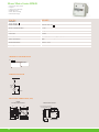
Electronic Timer - Series MiconTM 780
• Selectable Dual-voltage: 110/240V AC,240/415V AC and 24V AC/DC
• Multi-function, Asymmetrical ON/OFF, and Star-Delta timers
• Selectable Contacts: One instant and One / Two delayed
• Large knobs for ease of setting
Cat. No.
70MDT0
70ADT0
70SDT0
Multi-function
Asymmetrical ON/OFF
Star- Delta
Parameters
Mode
Functional Diagram
15-18
Ts
INSTANT RLY
TON TOFF
25-28
P
RELAY R2 (INSTANT)
TON = ON Time
TOFF = OFF Time
Supply Voltage ( )
Supply Variation
Frequency
110 VAC / 240 VAC
- 20% to +10% (of )
50/60 Hz
Timing Ranges
0.1s to 10h
N.A.
100 ms (max.)
Pause Time
Reset Time
Accuracy
Setting Accuracy
Repeat Accuracy
0.1s to 10h (ON & OFF Both)
Ts = Set Time
P = Pause Time
0.3s to 120s
60ms, 90ms, 120ms, 150ms
± 5% of Full scale
± 1%
Relay Output
1 Instant + 1 Delayed or 2 Delayed C/O (Selectable)
Contact Rating
Contact Material
Electrical Life
Switching Frequency
@ rated max load
Operating Temperature
Storage Temperature
For-110/240 V AC Model - 10A (resistive) @ 240 VAC & For-240/415 V AC Model - 5A (resistive) @ 415 VAC
AgSnO
1x10⁵
1000 operations/h (Max.)
LED Indication
Enclosure
Dimension (W x H x D) (in mm)
Weight (unpacked)
Mounting
Green LED
Power ON, Red LED
Flame Retardant UL94V0
55 X 78 X 104
210 g
Star - 1 'NO', Delta - 1 'NO'
-10° C to +55° C
-20° C to +70° C
Relay ON
Red 1-
ON, Red 2-
ON
Base / DIN Rail
Certification
EMI/ EMC
Radio Interference Suppression
ESD
Electrical Fast Transients
Surges
Voltage Dips & Interruptions
CISPR 14-1
IEC 61000-4-2
IEC 61000-4-4
IEC 61000-4-5
IEC 61000-4-11
Ed. 5.0 (2005-11) Class A
Ed. 1.2 (2001-04) Level II
Ed. 2.0 (2004-07) Level IV
Ed. 2.0 (2005-11) Level IV
Ed. 2.0 (2004-03) All 7 Levels (AC), IEC 61000-4-29
Ed. 1.0 (2000-08) All 5 Levels (DC)
ORDERING INFORMATION
Description
Cat. No.
70MDT0
74MDT0
76MDT0
110/240 VAC, Multi-function
240/415 VAC, Multi-function
24 VAC/DC, Multi-function
70ADT0
74ADT0
76ADT0
110/240 VAC, Asymmetrical ON/OFF
240/415 VAC, Asymmetrical ON/OFF
24 VAC/DC, Asymmetrical ON/OFF
70SDT0
74SDT0
110/240 VAC, Star-Delta
240/415 VAC, Star-Delta
17
Electronic Timer - Series MiconTM 780
MOUNTING DIMENSION (mm)
CONNECTION DIAGRAM
INSTANT
INSTANT
,
(70SDT0)
TERMINAL TORQUE & CAPACITY
STAR
(74SDT0)
18
DELTA
Electronic Timer - Series StaircaseTM
• Compact 17.5mm wide with 10 operating modes
• Time Range: 0.5min - 20min
• Long Run mode with time range from 0.5h - 20h
• Functions with pre-warning & maintenance mode available
• Switch indications (glow-lamps / pilot lamps) upto 50 mA
• 3 wire & 4 wire configurations
Cat. No.
27B1C3B1
Supply Voltage ( )
Supply Variation
Frequency
Signal Supply Range
230 VAC
- 25% to +15% (of )
50/60 Hz
As per Supply Voltage (
Power Consumption (Max.)
Modes
3 VA
Timing Ranges
)
1. Staircase Relay, 2. Staircase Relay with Pre-Warning, 3. Staircase Relay with Cut-Off, 4. Staircase Relay with CutOff & Pre-Warning, 5. Timing Step with Release Delay & Cut-Off, 6.Timing Step with Release Delay, Cut-Off & PreWarning, 7. Long Run, 8. Long Run with Pre-Warning, 9. Step Relay, 10. Permanent ON, 11. Maintenance Mode
0.5m, 2m, 4m, 6m, 9m, 15m, 20m (The unit will change from minutes to hours for ‘Long Run’ modes )
=5s (For modes 7, 8, 11)
=5 s), the timer will enter ‘Maintenance mode’
Signal Sensing Time
40 ms < Ts < 5 s (For modes 1, 2, 3, 4, 5, 6, 9) & Ts
Maintenance Mode
Accuracy:
Setting Accuracy
Repeat Accuracy
If the Relay is ‘OFF’ and the signal is present for 5 sec or more (Ts
Relay Output
Contact Rating
Contact Material
Electrical Life
Mechanical Life
LED Indication
Operating Temperature
Storage Temperature
Humidity (Non Condensing)
1 NO (Pole is internally short with ‘Live’)
16A @ 230 VAC
AgSnO
1X10⁵
1X10⁷
Green LED
Power ON, Yellow LED
Relay ON
-10°C to +60°C
-20°C to +70°C
95% (Rh)
Enclosure
Dimension (W x H x D) (in mm)
Weight (unpacked)
Flame Retardant UL94-V0
18 X 60 X 85
70 g
Mounting
Base / DIN rail
Certification
Degree of Protection
EMI/ EMC
Harmonic Current Emissions
ESD
Radiated Susceptibility
Electrical Fast Transients
Surges
Conducted Susceptibility
Voltage Dips & Interruptions
Conducted Emission
Radiated Emission
Environmental
Cold Heat
Dry Heat
Vibration
Repetitive Shock
Non-repetitive shock
± 5% of Marking
± 1%
RoHS Compliant
IEC 60669-2-3
IP 20 for Terminals, IP 40 for Enclosure
IEC 61000-3-2
IEC 61000-4-2
IEC 61000-4-3
IEC 61000-4-4
IEC 61000-4-5
IEC 61000-4-6
IEC 61000-4-11
CISPR 14-1
CISPR 14-1
Ed. 3.0 (2005-11) Class A
Ed. 1.2 (2001-04) Level II
Ed. 3.0 (2006-02) Level IV
Ed. 2.0 (2004-07) Level IV
Ed. 2.0 (2005-11) Level III (On Supply) & Level II (On Signal)
Ed. 2,2 (2006-05) Level III
Ed. 2.0 (2004-03) Performance Criteria B/A
Ed. 5.0 (2005-11) Class A
Ed. 5.0 (2005-11) Class A
IEC 60068-2-1
IEC 60068-2-2
IEC 60068-2-6
IEC 60068-2-27
IEC 60068-2-27
Ed. 6.0 (2007-03)
Ed. 5.0 (2007-07)
Ed. 7.0 (2007-12) 5g
Ed. 4.0 (2008-02) 40g, 6ms
Ed. 4.0 (2008-02) 30g, 15ms
ORDERING INFORMATION
Cat. No.
27B1C3B1
27C1C3B1
Description
230 VAC, Staircase Timer (10 Modes), 1 NO, Light Grey Casing
230 VAC, Staircase Timer (10 Modes), 1 NO, Dark Grey Casing
CONNECTION DIAGRAM
For Mounting Dimensions, Terminal Torque & Terminal Capacity refer page no. 5 & 6
19
Electronic Timer - Series StaircaseTM
FUNCTIONAL DIAGRAMS FOR 27B1C3B1 & 27C1C3B1
1. STAIRCASE RELAY
2. STAIRCASE RELAY WITH PRE-WARNING
<5s
<5s
<5s
T
<5s
<5s
<5s
T
T
10
<5s
10
10
10
T
T
T
On initial signal, the output closes & timing starts for the preset duration. Subsequent signals
during the run time will extend the time duration by the full preset value
3. STAIRCASE RELAY WITH CUT-OFF
<5s
<5s
T
<2s
4. STAIRCASE RELAY WITH CUT-OFF & PRE-WARNING
<2s
<5s
=
<5s
<5s
=
2s
<5s
<2s
2s
T
T
10 10
10
10
10
10
T
T
T
T
T
T
On initial signal, the output closes & timing starts for the preset duration. Subsequent signals
during the run time will extend the time duration by the full preset value. If a signal of
duration more than 2 seconds is applied, the output contacts open instantly.
6. TIMING STEP WITH RELEASE DELAY & CUT-OFF &
PRE-WARNING
5. TIMING STEP WITH RELEASE DELAY & CUT-OFF
<5s <2s
<5s
T
<2s
<5s
T
=
<5s
<5s
<2s
=
2s
<5s
2s
T
T
10 10
10 10
T
T
10 10
On initial signal, the output closes & timing starts for the preset duration. During run time, if a
signal of duration less than 2 seconds is applied, it is ignored. If the duration is more than 2
seconds, the output contacts open instantly
7. LONG RUN
8. LONG RUN WITH PRE-WARNING
=
=
<5s
5s
=
5s
=
5s
=
5s
=
5s
<5s
5s
T
T
10 10
10 10
T
T
On initial signal, the output closes & timing starts for the preset duration. On completion of
the time duration the output contacts open. Any signal during the run time is ignored.
9. STEP RELAY
<5s
<5s
<5s
<5s
After every signal, the output changes state, alternately switching from open to closed &
vice versa.
11. MAINTENANCE MODE
If the relay is OFF and a signal of duration more than 5 seconds is applied, the maintenance
mode is activated. In this mode the output contacts close for a duration of 60 minutes after
which it opens. During this period if a signal of duration more than 5 seconds is applied, the
maintenance mode is interrupted and the output contacts open. The mode can be activated
from any one of the modes (Mode 1, 2, 3, 4, 5, 6, 9) provided that the output contacts are
open.
10. PERMANENT ON
In this mode the output contacts are permanently closed until the mode is changed and the
device is reset.
=
5s
=
5s
=
5s
With Warning:
10
Without Warning:
10
10
1 hr
< 1 hr
1 hr
< 1 hr
10
Pre-Warning:
On completion of the set time duration the output blinks once & again blinks twice after a delay of 10 seconds and the contacts open after a further delay of 10 seconds.
20
Digital Timer
®
• Compact 17.5 mm
• Multi-voltage, Multi-function(8 or 17)
• 3 digit LCD for Preset time and Run time
• Option to select Up/Down counting
• Tamper proof with key lock function
• All settings accomplished with only two keys
• Up to 999 Hours
Cat. No.
V0DDTS1, V0DDTS
V0DDTD1, V0DDTD
Parameters
Supply Voltage ( )
Supply Variation
Frequency
Power Consumption (Max.)
Timing Ranges
Repeat Accuracy
Relay Output
24 - 240 VAC/DC
-15% to +10% (of )
50 / 60 Hz, + / - 2 Hz
10 VA
0.1s to 999h
+/- 0.5% of selected range
1 C/O (SPDT)
2 NO (DPST)
Contact Rating
Contact Material
Electrical Life
Mechanical Life
Switching Frequency
@ rated max load
Utilization Category
8A (resistive) @ 240 VAC / 24 VDC
AgSnO2
1x10 5
2x10 7
1800 Operations / h
AC - 15
DC - 13
Operating Temperature
Storage Temperature
LED Indication
Enclosure
Dimension (W x H x D) (in mm)
Weight (unpacked)
Mounting
Rated Voltage (Ue): 125/240 V, Rated Current (Ie): 3/1.5 A
Rated Voltage (Ue): 125/250 V, Rated Current (Ie): 2/0.22/0.1 A
-10° C to +55° C
-20° C to +65° C
Red LED
Relay ON
Flame Retardant UL94V0
17.5 X 89 X 76
85 g
Base / DIN rail
Certification
RoHS Compliant
Degree of Protection
Humidity (Non Condensing)
EMI/ EMC
Radio Interference Suppression
ESD
Electrical Fast Transients
Surges
Voltage Dips, Interruptions
Vibration
IP 20 for Terminals, IP 30 for Enclosure
95% (Rh)
CISPR 14-1
IEC 61000-4-2
IEC 61000-4-4
IEC 61000-4-5
IEC 61000-4-11
Ed. 5.0 (2005-11) Class A
Ed. 1.2 (2001-04) Level II
Ed. 2.0 (2004-07) Level IV
Ed. 2.0 (2005-11) Level IV
Ed. 2.0 (2004-03) All 7 Levels (AC), IEC 61000-4-29
Ed. 1.0 (2000-08) All 5 Levels (DC)
ORDERING INFORMATION
Cat. No.
V0DDTS
V0DDTD
V0DDTS1
V0DDTD1
Description
24-240 VAC/DC, 8 Functions, 1C/O
24-240 VAC/DC, 8 Functions, 2 NO
24-240 VAC/DC, 17 Functions, 1C/O
24-240 VAC/DC, 17 Functions, 2 NO
MOUNTING DIMENSION (mm)
CONNECTION DIAGRAM
V0DDTD1,
V0DDTD
Supply Connections
A1
15
V0DDTS1,
V0DDTS
25
15
B1
A2
18
18
OPTIONAL
LOAD >1mA
16
28
8A@
8A@
TERMINAL TORQUE & CAPACITY
Torque 0.54 N.m (5 Lb. in)
Ø3.5 mm
Terminal Screw M2.5
1 x 0.2 - 2.5 mm2 Solid Wire /
single wire ferrule
2 x 0.2 - 0.5 mm2 Insulated with
twin ferrule
AWG
1 x 22 to 14
21
Digital Timer
®
FUNCTIONAL DIAGRAMS FOR V0DDTS1 & V0DDTD1
U
U
ON DELAY [0]
SIGNAL
OFF DELAY [9]
R
T
R
T
TOFF
IMPULSE ON/OFF [A]
TOFF
R
TON
TON
SIGNAL OFF/ON [b]
TON
R
LEADING EDGE
IMPULSE1 [C]
T
T
t1
t2
T+t1+t2
U
t1
t2
T+t1+t2
T
when B1 is opened, R energizes and de-energizes when
timing is over. If B1 is closed during timing R resets.
U
B1
t1
R
T+t1+t2
TRAILING EDGE
IMPULSE2 [F]
t2
B1
R
T
When supply is ON, R energizes. When switch B1 is closed timing is suspended and
remains suspended till switch B1 is opened again. Interrupting supply resets timer.
T
T
When switch B1 is opened, R energizes and will de-energize
when timing is over. If B1 is pulsed during timing period it will have no effect on R.
U
U
DELAYED
IMPULSE [G]
B1
T
Timing starts when switch B1 is closed. R energizes at
end of timing period and de-energizes when B1 is opened.
B1
R
TON
TOFF
when switch B1 is closed, TOFF starts. Relay energizes at the end of TOFF period. Then,
TON starts irrespective of signal level and relay de-energizes at the end of TON period.
U
B1
T
Timing will commence when supply is present and switch B1 is open. R energizes
after timing .If B1 is closed during timing period, timing resets to the beginning of cycle.
22
B1
R
T
U
R
T
when switch B1 is closed, and remains closed output
relay energizes until timing is over. If B1 is opened during timing, R resets.
TRAILING EDGE
IMPULSE1 [E]
Time commences as supply is present and switch B1 is closed. Opening switch B1 pauses
timing. Timing resumes when switch B1 is closed again. R energizes at end of timing.
R
T
B1
R
T
U
R
T
U
LEADING EDGE
IMPULSE2 [d]
Time commences as supply is present and switch B1 is open. Closing switch B1 pauses
timing. Timing resumes when switch B1 is opened again. R energizes at the end of timing.
B1
T
When B1 is closed, output relay
energizes until timing irrespective of any further action of B1.
B1
R
INVERTED SIGNAL
ON DELAY [8]
T
B1
R
U
SIGNAL ON DELAY [7]
T
When switch B1 is closed or opened for preset time ,T, the
relay changes its state after time duration T.
U
U
After power ON, R energizes and timing starts. R de-energizes after timing is over.
ACCUMULATIVE IMPULSE
ON SIGNAL [6]
T
B1
R
TOFF
This function is quite similar to the function ‘1’ but initially the relay(R) is ON for period
T-ON after the power is applied.
ACCUMULATIVE DELAY
ON INVERTED SIGNAL [5]
T
U
TOFF
ACCUMULATIVE DELAY
ON SIGNAL [4]
T
R energizes for the timing period when B1 is opened or
closed. When timing commences, changing state of B1 does not affect R but resets timer.
U
R
B1
R
TON
T-ON and T-OFF can be same or different. The relay(R) keeps on changing its status
till power is removed.
IMPULSE ON
ENERGIZING [3]
T
U
U
CYCLIC ON/OFF
{ON start, (Sym, Asym)} [2]
T
R energizes when switch B1 is closed. Timing
commences after S is opened and then the relay de-energizes.
Timing commences when supply is present.R energizes
at the end of the timing period.
CYCLIC OFF/ON
{OFF Start, (Sym, Asym)} [1]
B1
Digital Timer
®
FUNCTIONAL DIAGRAMS FOR V0DDTS & V0DDTD
P : A1- A2
P: Power-On operation
S : B1
ON DELAY ( A)
T
R :
S :
B1
CYCLIC OFF/ON
{OFF Start, (Sym, Asym)} ( b)
T OFF T ON T OFF T ON
R :
S : B1
CYCLIC ON/OFF
{ON Start, (Sym, Asym)} ( C)
T ON
T OFF T ON
T OFF
R :
S : B1
SIGNAL ON/OFF ( d)
T
T
T
T
R :
S : B1
SIGNAL OFF DELAY ( E)
T
R :
S :
B1
INTERVAL ( F)
T
R :
S :
B1
SIGNAL OFF / ON ( G)
T
T
T
T
R :
B1
ONE SHOT OUTPUT ( H)
S :
T
1 SEC.
R :
Note:
1. For Power-On operation (P) connect the terminal B1 to A1 permanently.
2. If the Signal (S) changes during the Timer Duration (T), it does not change the output relay but re-triggering
takes places and the Timer Duration is extended.
23
Synchronous Timer - Series EM 1000
• Time delay is independent of normal voltage and temperature fluctuations
• Black pointer gives clear indication of the time set on the calibrated dial
while the red one indicates the time left to complete the cycle
• Automatic reset on de-energisation of the clutch coil
• Base mounting or flush mounting versions
• No-volt feature available
On - Delay
Mode
On - Delay (Retentive / No Volt)
Functional Diagram
R
R
T
= Supply, R = Relay, T = Set Time
<
<
<
t2
<
<
t3
<
<
T = t1 + t2 + t3
Supply Variation
Frequency Variation
Power Consumption (Max.)
Timing Range
Repeat Accuracy
- 20% to +10%
95% to 105%
10 VAC
0.15s to 120h
± 0.5% of FSR at constant Frequency
Contact Rating
1 Inst + 1 delayed - AgCdO
1 Inst + 2 delayed - AgCdO (Optional)
6A (resistive) @ 250 VAC
3000 operations/hr. (Max.)
Switching Frequency
Operating Temperature
Enclosure
Dimension (W x H x D) (in mm)
Weight (unpacked)
Mounting
t1 <
- 5°C to + 45°C
Conforms to IP30 - IS 13947.
96 X 96 X 100
530 g
Flush & Base
1– 2.5 mm² solid/ stranded
IP20
Terminal Connection
Degree of Protection
ORDERING INFORMATION
B
Timing Ranges(SR)
B
C
D
E
F
G
H
J
K
L
M
N
P
Q
R
S
T
V
0.15 - 3.0
1.5 - 30
0.15 - 3.0
1.5 - 30
0.15 - 3.0
1.5 - 30
0.3 - 6.0
3.0 - 60
0.3 - 6.0
3.0 - 60
0.3 - 6.0
3.0 - 60
0.6 - 12
6.0 - 120
0.6 - 12
6.0 - 120
0.6 - 12
6 - 120
SEC
SEC
MIN
MIN
HRS
HRS
SEC
SEC
MIN
MIN
HRS
HRS
SEC
SEC
MIN
MIN
HRS
HRS
Delay
1 Standard ON delay
2 With ‘NO VOLT’
Mounting
B Base Mounting
F Flush (door) Mtg.
Contact
1 1 Inst + 1 Del C/O
2 1 Inst + 2 Del C/O
Timing Ranges(MR)
Voltage
X 0.15 SEC.-3.0 HRS.
3 110V AC 50 Hz
Y 0.3 SEC.- 6.0 HRS.
Z 0.6 SEC.-12.0 HRS. 4 240V AC 50 Hz
C 110V AC 60 Hz
D 240V AC 60 Hz
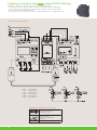
WIRING DIAGRAMS OF SERIES EM1000
Clutch
Instant
1
3
Motor
5
Delay
15
8
6
11
9
M
2
4
16
7
10
MOUNTING DIMENSION (mm)
BASE MOUNTING
Mounting Hole
25.5
Ø8
15.5
Knob
Ø5
4
2
1
5
0
118
130
90 mm Dia.
96
3
6
GENERAL INDUSTRIAL CONTROL
Panel Max. 10mm
96
Note : Panel Cutout 91mm Dia.
24
100 mm
27
84
96
Terminals
132
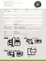
Synchronous Timer - Series EM 2000
• Time delay is independent of normal voltage & temperature fluctuations
• Large knob operating on a linear scale makes time setting easy
• Set time is indicated by a fixed pointer of the setting knob.
• Time left for completion of cycle is indicated by red pointer
• Wiring is quicker and easier as terminals are in the front of the unit
• All part subjected to wear & tear are made of 'Delrin' which has high
resistance to wear & tear and thus ensures longer life.
On - Delay
Mode
Functional Diagram
R
T
= Supply, R = Relay, T = Set Time
Supply Variation
Frequency Variation
Timing Range
Accuracy :
Repeat Accuracy
- 20% to +10%
95% to 105%
1s to 120s
Contact Rating
Switching Frequency
1 delayed - AgCdO
2 delayed - AgCdO (Optional)
5A (resistive) @ 250 VAC
1000 operations / hr. (Max.)
Operating Temperature
-5°C to 45°C
Enclosure
Dimension (W x H x D) (in mm)
Weight (unpacked)
Mounting
Conforms to IP30 - IS 13947.
55 X 88 X 106
260 g
Base/DIN Mounting & can be mounted on vertical plane with maximum inclination of 15° from vertical.
Terminal Connection
1– 2.5 mm² solid/stranded.
Degree of Protection
IP20
± 2% of FSR at constant Frequency
ORDERING INFORMATION
C
B 1
Timing Ranges
Voltage
3 110V AC 50 Hz
4 240V AC 50 Hz
5 415V AC 50 Hz
C 1.0 - 30 Sec
J 2.0 - 60 Sec
Q 4.0 - 120 Sec
Contact
5 1 Del C/O
6 2 Del C/O
WIRING DIAGRAMS OF SERIES EM2000
15
A1
M
25
S2
15
S1
A1
M
A2
A2
16
18
16
18
26
28
Note : Switch 2 operates before switch 1
MOUNTING DIMENSION (mm)
BASE/DIN MOUNTING
DIN RAIL
45.0 C/C
(35 mm SYMMETRICAL)
88.0 C/C
78.0
4.8
6.8
5.5
96.5
55.0
106.0
25
Glossary
Operating Voltage:
Input Supply required for operation.
Supply Variation:
Allowable variation in input power supply for satisfactory operation.
Delayed Contacts:
A contact in a timer that changes state at the end of time that has been set.
Instantaneous Contact:
A contact that changes state as soon as power is switched on to the timer.
Electrical Life:
The number of operations that the contact can be expected to make or break at the rated
electrical load.
Reset Time:
Time taken by the timer to start a new cycle.
Repeat Accuracy:
It indicates how consistently the device will repeat the time. It is more important where
uniform processing time cycles are required.
Rated Current:
A current that can flow continuously through the closed contact.
Contact Rating:
Voltage and current, which can switch under specified conditions.
Storage / Ambient Temperature:
Temperature surrounding the product.
Power Consumption:
Power absorbed by the unit for its own satisfactory functioning.
Mounting:
The type of placement of the unit (Base/Din/Flush).
No-volt protection (Retentive Timer):
Timers are available with retention ensuring that elapsed time is not cancelled when the
supply is interrupted during the timing cycle.
26
Operating Modes / Functions
MULTIFUNCTIONAL
• Delay on Energisation (ON Delay): The set time (Delay) starts
when the timer receives supply. The output relay energises at the
end of the pre-set time
INST. RELAY
• Cyclic Instant (Equal ON/OFF): On energisation, relay output
switches ON and OFF repeatedly for the set time. Cycle starts
with relay in energised condition. When supply is switched OFF,
the relay is reset.
RELAY
ON DELAY
T
RELAY
• Interval Timer: On energisation of Timer, Output relay changes
the state for the time set. After completion of set time, output
relay de-energises. By switching off the supply, the Timer gets
de-energised & is ready for the next cycle of operation.
CYCLIC
T
T
RELAY
INTERVAL
• (Signal)-OFF delay: Timer is energised and relay is in OFF
condition. When control input is given through control contacts,
relay is energised. Delay period commences when control input
is removed. At the end of set time, relay is de-energised and load
is disconnected.
T
CONTROL
SIGNAL
OFF DELAY
RELAY
T
STAR - DELTA
Relay
Relay
T
Tp
Set Time
Pause Time
• Star - Delta: The timer has a fixed transition time from Star to
Delta connection. On energisation, the output star relay energises
instantly. After completion of preset delay time, output Delta
relay energises after fixed pause time. This pause time (60, 90,
120, 150 ±20 ms ) provides the shortest possible 'current off'
pause and simultaneously ensures smooth change over.
ASYMMETRICAL
ON/OFF
Toff
Relay R1, R2
Ton
DLY
Relay R2
INST
• Asymmetrical ON/OFF (Cyclic Instant): ON/OFF, can be
independently selected from 0.1 Sec. to 10 Hrs. On energisation,
relay output switches on and off repeatedly for the respective set
times. Cycle starts with relay in energised condition. By
removing supply, the relay is reset.
TRUE OFF DELAY
(POWER OFF DELAY)
MODE
• True OFF Delay: On energisation the Relay O/P is in ON Position.
Timing delay period commences when supply to the True OFF
Delay Timer goes OFF. The O/P Relay de-energises at the end of
pre-set time.
FUNCTION
Relay
T
ON DELAY
(RETENTIVE/NO VOLT)
MODE
Relay
FUNCTION
<
<
t1 <
<
t2 <
T
T= t1 + t2 + t3
<
t3 <
<
• ON Delay (Retentive): The set time (Delay) starts when timer
receives supply. The output relay energises at the end of the preset time. If power fails during set time, the elapsed time will
retained by timer. Upon resumption of power, remaining cycle
will continue.
27
28
GIC
www.gicindia.com
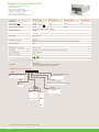
TIME SWITCHES
Time Switch FM Series
Digital Time Switch
Astronomical Time Switch
Astronomical Time Switch
Lighting Automation with
Using GSM Technology
Time Switch FM Series
• Modular construction
• Inbuilt over-ride facility
• High switching capacity
• Tamper proof sealing
• Analog & Digital version
• Daily/Weekly programming
• Graphical Program LCD
J648B1 (Analog Version)
Cat. No.
Parameters
Supply Voltage
Frequency
D847B2 (Digital Version)
Power Consumption (Max.)
Accuracy
Switching contact
240 VAC
50/60 Hz
2 VA
± 1.5 s/day at 20°C
1 C/O contact - AgCdO
Contact Rating
- Resistive
- Inductive (cosø = 0.6)
- Incandescent Lamp
16A @ 250 VAC, 0.25A @ 220VDC
8A @ 250 VAC, 0.1A @ 220 VDC
1350 W
16A @ 250 VAC
4A @ 250 VAC
1350 W
Shortest Switching Time
- Daily
- Weekly
15min
2h
1min
1min
150h
N. A.
10 years from Factory at 20°C
20
Power reserve
Memory locations
Storage Temperature
4.4 VA
± 1 s/day at 20°C
- 20°C to + 55°C
Provided
Flush, Base / DIN rail
185 g
Manual Over-ride
Mounting
Weight (unpacked)
ORDERING INFORMATION
Description
Cat. No.
J648B1
J848B1
J638B1
J838B1
D847B2
FM/1 QT
FM/1 QW
FM/1 QT
FM/1 QW
FM/1 Digi20 Plus
Daily dial, 240 VAC, Base / DIN Mounting
Weekly dial, 240 VAC, Base / DIN Mounting
Daily dial, 110 VAC, Base / DIN Mounting
Weekly dial, 110 VAC, Base / DIN Mounting
Weekly / Daily, 240 VAC, Base / DIN Mounting
Note: For Flush Mounting model replace B by F in Cat. No.
F
TIME SETTING:
Rotate the switching Dial in clockwise direction until the current time (day / time incase of weekly model) is
almost opposite to the marking arrow F. For fine adjustment rotate the minute hand in the clockwise direction
until the clock shows the current time.
PROGRAMMING:
Required Switch ON time is set on the Switching Dial by radially pulling outwards the corresponding black
segments. Each segment on daily dial corresponds to 15 mins. & on weekly Dial corresponds to 2 hours.
CONNECTION DIAGRAM
MOUNTING DIMENSION (mm)
72.0 SQ
52.0
MAX. 4.5
39.5
1
30.95
102.5
66.00
(Time Switch)
TS
2
I
3
Permanent
'ON'
NO NC
4
5
As per
Programme
P
N
14.70
SCREW
20.50
72.0
LOAD
34.50
66.0
Torque 1.1 N.m (10 Lb. in)
Base Mounting
Flush Mounting
4.0 mm
1 x 0.2 - 5 mm2 Solid Wire /
single wire ferrule
TERMINAL TORQUE & CAPACITY
2 x 0.2 - 2.5 mm2 Insulated with
twin ferrule
AWG
30
Terminal Screw - M 3.5
1 x 24 to 10
0
Permanent
'OFF'
Digital Time Switches
TM
&
• Precise time programming for Daily/Weekly/Pulse switching
• 25 ON/OFF programs
• Weekend exclusion (FRI SAT or SAT SUN) and Weekly OFF programming
• LED indication of Relay status
• 12/24 h display formats
• 6 years battery reserve
• Simple Reset & Manual override
• DST Feature Available
67DDT0 (
Cat. No.
Parameters
Supply Voltage & Frequency
Number of Modes & Description
)
TM
110 - 240 VAC, -20 % +10%, 50 / 60 Hz
Five
- Program Run
• AUTO
• ON AUTO - Instant ON up to next ON Program
• AUTO OFF - Instant OFF up to next OFF Program
- Continuous ON
• ON
- Continuous OFF
• OFF
67DDT9 (
Three
• AUTO
• ON
• OFF
25 ON/OFF Programs
Minimum Switching Time
AC - 15
Utilization Category
DC - 13
Power Consumption (Max.)
Operating Temperature
Storage Temperature
DST
Clock Accuracy
Power Reserve from Factory
Switching Contacts
1min
Rated Voltage (Ue): 120/240 V, Rated Current (Ie): 3/1.5 A
Rated Voltage (Ue): 24/125/250 V, Rated Current (Ie): 2.0/0.22/0.11 A
6 VA
-10°C to + 55°C
-10°C to + 60°C
Settable ( 1 Hour)
± 2 s/day max. over the Operating Temperature range
6 Years
1 C/O (SPDT)
Resistive: - 16A (For 'NO') & 5A (For 'NC') @ 240 VAC / 24 VDC
Inductive (cos ø = 0.6) :- 6 A @ 250 VAC
Incandescent Lamp: - 1000 W
3x10⁴
Ag Alloy
50 X 103
Red
Relay ON
Flame Retardant UL94V0
36 X 65 X 90
120 g
Base / DIN rail
IP 20 for Terminals, IP 40 for Enclosure
Electrical Life
Contact Material
Mechanical Life
LED Indication
Enclosure
Dimension (W x H x D) (in mm)
Weight (unpacked)
Mounting
Degree of Protection
- Program Run
- Continuous ON
- Continuous OFF
16 Pulse Programs
(Ex - 0,1,2,3,4,5,6,7,8,9, a, b, c, d, e, f)
1s
Number of Programs
Contact Rating
)
Certification
RoHS Compliant
EMI/ EMC
Radio Interference Suppression
ESD
Electrical Fast Transients
Surges
Voltage Dips & Interruptions
Applications
CISPR 14-1
Ed. 5.0 (2005-11) Class B
IEC 61000-4-2
Ed. 1.2 (2001-04) Level II
IEC 61000-4-4
Ed. 2.0 (2004-07) Level IV
IEC 61000-4-5
Ed. 2.0 (2005-11) Level IV
IEC 61000-4-11 Ed. 2.0 (2004-03) All 7 Levels (AC), IEC 61000-4-29
Ed. 1.0 (2000-08) All 5 Levels (DC)
Ideal for Lighting applications like street lighting,
Ideal for Siren, School bell application
Advertising Displays, Glowsigns. Also can be used for
Air conditioners / Coolers, Geysers, conveyors,
pumps etc.
ORDERING INFORMATION
Description
Cat. No.
67DDT0
67DDT9
110 - 240 VAC (50/60 Hz), 1 C/O (SPDT)
110 - 240 VAC (50/60 Hz), 1 C/O (SPDT)
TIME & DAY SETTING:
Press RST key. Press key & keep it pressed. Then press D + key to set running day. Press H + key
to set running hour & press M + key to set running Minute.
FUNCTIONS OF KEYS:
PRG
D+
H+
:
:
:
:
RST
:
MAN / (-) key :
To enter the programing mode & selection of ON/OFF programs
To increment & select any particular day / combination of days
To increment hours, M + : To increment minutes
To set the clock & change the time format (AM / PM or 24 Hour format)
To reset programs & clock
For mode setting (Manual override) / to decrement day, hour & minute in programming mode / DST
PROGRAMMING:
PROGRAMMING:
To set a program - Press PRG key.
Set 1 ON time, day, then 1 OFF time, day
with the help of D+, H+ & M+ keys.
We can set total of 25 ON & 25 OFF programs.
To set a program - Press PRG key.
(a) If pulse is common or the same, set pulse
before the ON time (b) If pulse time is different
for different programs, set the ON time first and
then set different pulse values for each
programme
DST:
Press H+ & M+ keys simultaneously to enter the DST mode.
To enable DST, press M+ key once.
To disable DST, press M+ key again.
31
TM
Astronomical Time Switch
• Astronomical Time Switch in 35mm size
• Latitude/Longitude precise to the minute with time zone
• Sunrise/Sunset or Twilight rise/set trigger modes
• Ease of programming & navigation
• DST, Offset, OFF Hours, Weekly OFF features
• 12/24 Hour display format
• 6 years battery reserve
• Easy Manual Override
• Ideal for Outdoor & Street lighting applications
T2DDT7
Cat. No.
Parameters
Supply Voltage & Frequency
Number of Modes & Description
110 - 240 VAC, -20 % +10%, 50 / 60 Hz
Three
- As per user defined program settings
• AUTO
• ON AUTO - Manual ON up to next auto event
• AUTO OFF - Manual OFF up to next auto event
Programming
Based on:
1) Latitude/Longitude precise to the minute with time-zone
2) Option for both Sunrise/Sunset & Twilight rise/set trigger
3) DST feature (1 Hour) with indication on screen
4) Weekly OFF
5) Offset for rise/set
6) OFF-Hours
Minimum Switching Time
AC - 15
Utilization Category
DC - 13
Power Consumption (Max.)
Operating Temperature
Storage Temperature
LCD Display
Clock Accuracy
Power Reserve from Factory
Switching Contacts
1min
Rated Voltage (Ue): 120/240 V, Rated Current (Ie): 3/1.5 A
Rated Voltage (Ue): 24/125/250 V, Rated Current (Ie): 2.0/0.22/0.11 A
6 VA
-10°C to + 55°C
-10°C to + 60°C
3 Lines Text LCD
± 2 s/day max. over the Operating Temperature range
6 Years
1 C/O (SPDT)
Resistive: - 16A (For 'NO') & 5A (For 'NC') @ 240 VAC / 24 VDC
Inductive (cos ø = 0.6) :- 6 A @ 250 VAC
Incandescent Lamp: - 1000 W
3x10⁴
Ag Alloy
50 X 103
Red
Relay ON
Flame Retardant UL94V0
36 X 65 X 90
110 g
Base / DIN rail
IP 20 for Terminals, IP 40 for Enclosure
Contact Rating
Electrical Life
Contact Material
Mechanical Life
LED Indication
Enclosure
Dimension (W x H x D) (in mm)
Weight (unpacked)
Mounting
Degree of Protection
Certification
RoHS Compliant
EMI/ EMC
Radio Interference Suppression
ESD
Electrical Fast Transients
Surges
Voltage Dips & Interruptions
CISPR 14-1
IEC 61000-4-2
IEC 61000-4-4
IEC 61000-4-5
IEC 61000-4-11
Ed. 5.0 (2005-11) Class B
Ed. 1.2 (2001-04) Level II
Ed. 2.0 (2004-07) Level IV
Ed. 2.0 (2005-11) Level IV
Ed. 2.0 (2004-03) All 7 Levels (AC), IEC 61000-4-29
Ed. 1.0 (2000-08) All 5 Levels (DC)
Street lighting applications in cities, industrial townships, university campuses
Lighting automation in sports complex, hotels, parks & other outdoor applications.
Applications
ORDERING INFORMATION
Description
Cat. No.
T2DDT7
110 - 240 VAC (50/60 Hz), 1 C/O (SPDT)
FUNCTIONS OF KEYS:
ESC
OK
ESC
RST
32
MAN
OK
RST
MAN
:
:
:
:
:
:
:
Previous Menu / Undo Change
Menu scroll up / Increase parameter value / View Output OFF time in standby mode
Menu scroll down / Decrease parameter value / View Output ON time in standby mode
Enter programming mode / selecting a particular parameter to edit / applying & confirming changes
Resets clock & other programs & settings to default
For mode setting (Manual override)
Exit programming mode / 12 or 24 Hour clock mode selection in standby mode
Astronomical Time Switches
• Dynamic and accurate control based on
astronomical mathematics
• Sunrise / Sunset or Twilight rise / set trigger
• Yearly programming with Season mode,
DST, Offset, Off hours, Weekly Off enabled
• Protection against under voltage and over voltage
• Alternate Mode with Auto load changeover feature
• Three independent channel outputs
Cat. No.
Parameters
Supply Voltage ( )
Supply Variation
Power Consumption (Max.)
Storage Temperature
Operating Temperature
Switching contacts
Electrical Life
Mechanical Life
Shortest switching time (daily)
Power reserve (for clock only)
Clock deviation
DST
Display
Under / Over Voltage Trip Level
Trip time for Under / Over Voltage
Recovery time
Mounting
Dimensions (W x H x D) (in mm)
EMI/ EMC
Radio Interference Suppression
ESD
Electrical Fast Transients
Surges
Voltage Dips & Interruptions
Degree of Protection
Pollution Degree
TM
• Active Phase selection
• Manual override facility
• Single phase and three phase versions
• Modbus Communication
• User friendly software for device configuration
T2DDT0
T3DDT0
110-240 VAC, 50/60Hz
-20% to +15% (of )
8VA @ 300 VAC
-10°C to + 60°C
-10°C to + 50°C
2 NO, 8A (resistive load) @ 240 VAC and
5A (resistive load) @ 30 VDC
105
107
1min (1 s for pulse)
1000 h
± 1 s per day over the operating temperature range
settable
Backlit LC Graphics display for diagnostic view
N. A.
N. A.
N. A.
Base / DIN rail
72 X 90 X 67
110-240 VAC 3 Phase 4 wire (P-N), 50/60Hz
3 NO, 8A( resistive load) @ 240 VAC and
5A (resistive load) @ 30 VDC
Settable UV: 0 - 220 V & OV: 130 - 330 V
5 - 16 Sec.
1 - 4 Sec.
CISPR 14-1
Ed. 5.0 (2005-11) Class A
IEC 61000-4-2
Ed. 1.2 (2001-04) Level II
IEC 61000-4-4
Ed. 2.0 (2004-07) Level IV
IEC 61000-4-5
Ed. 2.0 (2005-11) Level IV
IEC 61000-4-11 Ed. 2.0 (2004-03) All 7 Levels (AC), IEC 61000-4-29
IP 20 for Terminals, IP 40 for Enclosure
II
Ed. 1.0 (2000-08) All 5 Levels (DC)
Certification
RoHS Compliant
Weight (unpacked)
190 g
208 g
ORDERING INFORMATION
Cat. No.
T2DDT0
T3DDT0
TGDDT6
GFDNN3M
GFDNN2S
GFDNN1
Description
110-240 VAC, 1 Phase, 2 NO (SPST)
110-240 VAC, 3 Phase 4 wire (P-N), 3 NO (SPST)
Windows based application software for Astro
Memory card
Serial interface cable
USB interface cable
TIME & DAY SETTING :
Q1-A
Q2-A
Q3-A
26-10-09
MON
11:45
ESC
Screen No. 1
DD/MM/YY
26/10/09
HH : MM
11 : 45
Screen No. 2
LONGITUDE
E 000' - 00'
LATITUDE
N 00' - 00'
Screen No. 3
1)
2)
3)
4)
5)
6)
Power ON the Astro. The screen No.1 will appear.
Press ESC key.
Set the cursor on "SETTINGS" with help of Z keys and press OK.
Set the cursor on "CLOCK" with help of Z keys and press OK.
Set the cursor on "DATE / TIME" with help of Z keys and press OK. Then screen No.2 will appear.
Press Z1 or Z3 key to locate the cursor at "DAY" parameter position. Then press "ALT" key to edit
the value of Day. When user presses this key, the upper digit of the Day parameter start blinking as
to show it is selected. Press Z2 or Z4 key to increment or decrement the value of digit under edit.
Press Z1 or Z3 key to select next digit of the parameter. Now again press Z2 or Z4 key to increment
or decrement the value of digit. If required value of the Day has edited then press OK key to set it &
come on the screen No. 1 by pressing the ESC key.
7) Similarly select other individual parameters and modify them as per your requirement &
save it as per the above given process.
LATITUDE & LONGITUDE :
1) Go to menu by pressing "ESC" key
2) Set the cursor on "SETTINGS" with help of Z keys and press OK
3) Go to "LAT/LONG" using Z2 Key. Then screen No. 3 will appear.
The cursor blinks at E. Press ALT Key to go into edit mode.
Change the direction using Z2 or Z4 key once the required direction is set press ALT to set the
direction. Jump to next character using either Z1 or Z3 key.
Press ALT again to enter into edit mode When user presses this key, the digit starts blinking.
Press Z2 ro Z4 key to increment or decrement the value of digit under edit.
Press Z1or Z3 key to select next digit of the parameter.
Now again press Z2 or Z4 key to increment or decrement the value of digit.
If the required value of latitude longitude has been edited then press OK key to save it.
GMT + 00 : 00
TIME ZONE :
Screen No. 4
4) Go to "CLOCK" and Press OK.
5) Select "TIME ZONE" and Press OK. Then screen No.4 will appear.
6) In the screen No. 4, edit sign, hour & minute as per your requirement. Then press OK to save
the changes & & come on the screen No. 1 by pressing the ESC key.
33
Astronomical Time Switches
Digital Time Switches
TM
MOUNTING DIMENSION (mm)
For: T2DDT0 & T3DDT0
&
DIN RAIL 35mm
TM
68.5
45.0
100.0 C/C
90.5
72.0
17.0
65.0
CONNECTION DIAGRAM
Supply
240 VAC
50/60 Hz
N
For: T2DDT0
P
250mA
Supply
3 -Phase
4 wire
240 VAC
50/60 Hz
L N
N
B Ph
For: T3DDT0
Y Ph
R
Ph
250mA
110 -240 VAC
50 / 60 Hz
R
BN
Y
110 - 240 V Ph - N AC [ 3Ph 4 Wire ]
50 / 60 Hz
DEL
Z4
ALT
Z3
Z1
DEL
Z4
ESC
Z2
OK
Astro
ESC
OK
OUTPUT
3 X RELAY / 8A
Q2
Q1
PHASE
R Ph
LOAD MC1
Z2
Astro
OUTPUT
2 X RELAY / 8A
Q1
ALT
Z3
Z1
MC2
Q2
YPh
MR
Q3
BPh
MY
MB
1. MC1 : - Coil of Contactor 1
1. MR: - Coil of Contactor 1
2. MC2 : - Coil of Contactor 2
2. MY: - Coil of Contactor 2
3. MB : - Coil of Contactor 3
Crono, Pulse & Astro Mini
TM
TM
CONNECTION DIAGRAM
MOUNTING DIMENSION (mm)
36.0
DIN RAIL 35mm
H+
RST
M+
TS
L
N
15
NO NC
18 16
68.5
45.0
D+
90.0
PRG
N
100.0 C/C
L
(Time Switch)
P
MAN
N
18
15
16
17.0
LOAD
65.0
TERMINAL TORQUE & CAPACITY
Torque 0.54 N.m (5 Lb. in)
3.5 mm
Terminal Screw - M 2.5
1 x 0.2 - 3.3 mm2 Solid Wire /
single wire ferrule
2 x 0.2 - 1 mm2 Insulated with
twin ferrule
AWG
34
1 x 24 to 12
Lighting Automation with
TM
using GSM Technology
• Most of the "ASTRO" parameters can be set remotely using SMS queries. I.e. Output mode, Offset Hrs etc, UV, OV settings.
• Relay Output can be override remotely using SMS query.
• Energy Meter Functionality. Parameter like Load current, Supply voltage, Power, Energy can be known remotely.
• With the help of "Auto Error Code Update" following onsite error can be know remotely during output event.
- Under Voltage
- Over Voltage
- Over Current
- Output actuator short.
- Load Open
Cat. No.
Parameters
Supply Voltage ( )
Supply variation
Active phase selection
Operating Temperature
GSM Type
GPRS packet data
AT command set
Suitability
SMS type functionality
SIM Holder
Antenna
Antenna Impedance
Energy Measurement
Energy Measurement Accuracy
Current sensing range
CT ratio
LED Indications
Pulse Out rate
Auxiliary Output
General Port Connectivity
Mounting
Enclosure
Colour
Dimension (W x H x D) (in mm)
Weight (unpacked)
19D20B00 (ERT 5)
110-240 VAC 3 Phase 4 wire (P-N), 50/60Hz
-30%, +25% (of )
Yes
-15oC to + 60oC
Dual band 900 / 1800 GSM
Class 10 coding scheme
N. A.
Data Call through GSM, SMS
Text, Cell Broadcast
Connected with the product
50
Yes
Class 0.5
5A
Settable up to 40
Tx, Rx, Network, Power, Pulse Out
3200 pulses / kWh
12 V DC, 200 mA
N. A.
1A
19C20C00
110-240 VAC, 50/60 Hz
Yes
GSM 7.05 & 7.07
No
N. A.
N. A.
N. A.
Tx, Rx, Network, Power, SIM Status
N. A.
N. A.
TTL port for connecting Time-switch
(Astro) USB through USB interface
cable GFDNN1, RS232 through
serial interface GFDNN2S, RS485
through TTL-RS485 converter
G7XDTR4"
DIN / Base
4 Modular
RAL 7016
72 X 90 X 67
190 g
Certification
EMI/ EMC
Harmonic Current Emission
ESD
Radiated Susceptibility
Electrical Fast Transients
Surge
Conducted Susceptibility
Voltage Dips and Interruptions
Radiated Emission
19D20A00 (ERT 1)
RoHS Compliant
IEC 61000-3-2 Ed. 3.0 (2005-11) Class A
IEC 61000-4-2 Ed. 1.2 (2001-04) Level II
IEC 61000-4-3 Ed. 3.0 (2006-02) Level III
IEC 61000-4-4 Ed. 2.0 (2004-07) Level IV
IEC 61000-4-5 Ed. 2.0 (2005-11) Level IV
IEC 61000-4-6 Ed. 2.2 (2006-05) Level III
IEC 61000-4-11 Ed. 2.0 (2004-03) All seven levels
CISPR 14-1 Ed. 5.0 ( 2005-11) Class A
Note:
1. ERT5 & ERT1 can measure maximum 5A & 1A current respectively.
2. Maximum current measurement limit for ERT-5 is 200A & for ERT-1 it is 40A.
Ex: 1. For CT selection if current required to be measured is upto 200A then CT of 200:5 A ( CT ratio 40) needs to be used.
2. For CT selection if current required to be measured is upto 40A then CT of 40:1 A ( CT ratio 40) needs to be used.
ORDERING INFORMATION
Cat. No.
Description
T3DDT0
Astro time switch, 110-240 VAC 3 Phase 4 wire (P-N), 50/60Hz, 3 NO (SPST)
19D2000C
Surge Suppressor
19D20B00
Astro GSM Module (GSM-ERT5), Remote Side
19D20A00
Astro GSM Module (GSM-ERT1), Remote Side
19C20C00
Astro GSM Module (GSM-RT), PC side
19A1000B
Communication Cable (TTL-TTL) between Astro & GSM Module
TGDDT6
Windows based application software for Astro
35
Lighting Automation with
TM
using GSM Technology
• Maximum 5 valid users can access the system remotely, using GSM functionality.
• To avoid Remote module's SIM theft, "SIM PIN" facility can be enabled remotely using SMS query.
• To avoid changes in system configuration by unauthorized user amongst valid users, important SMS
queries are provided with "MODULE PIN" lock.
• Device supports for 12 to 14 digit mobile number. i.e. (10 Digit Mobile number + 2/3/4 digit country code).
CONNECTION DIAGRAM
1. MR:
2. MY:
3. MB:
4. MRC1:
5. MRC2:
6. MRC3:
-
Coil of Contactor 1
Coil of Contactor 2
Coil of Contactor 3
NO of Contactor 1
NO of Contactor 2
NO of Contactor 3
C. T.
TERMINAL TORQUE & CAPACITY
3.5 mm
Torque 0.54 N.m (5 Lb. in)
Terminal Screw - M 2.5
1 x 0.2 - 3.3 mm2 Solid Wire /
single wire ferrule
2 x 0.2 - 1 mm2 Insulated with
twin ferrule
AWG
36
1 x 24 to 12
GIC
www.gicindia.com
HOUR METERS & COUNTERS
Hour Meter Series HM 36
Hour Meter Series HM 48
Digital Hour Meters
Impulse Counter Series CR 26
Digital Counters
Hour Meter Series HM36
• Robust design with high degree of accuracy and compact size
• Frequency independent for AC applications
• Indicates operating time in hours and tenths with running indicators
• Totally sealed from dust and moisture
• Panel mountable with 7 bezel options
• Non-resettable
• 6 digit version with automatic recycle to zero
• Wide supply voltage range: 4-30V AC/DC, 10-80V DC & 90-264V AC
• Shock & Vibration Proof
Cat. No.
Parameters
Supply Voltage (
Frequency
)
AC Model HM36
DC Model HM36
AC/DC Model HM36
90-264 VAC, 50/60 Hz
50/60 Hz
10-80 VDC
10-80 N. A.
Protected for 2 times battery
voltage and / or reverse polarity
4-30 VAC / DC, 50/60 Hz
50/60 Hz
Not applicable to AC and 48V
for DC Application
0.25 VA
1 VA
Over Voltage &
reverse polarity protection
-----------------
Power Consumption (Max.)
Register
0.5 VA
6 Digit (3.6mm)
Read Out
Least Count
Accuracy
99999.9
1/10 h
± 0.02% over entire range
10-80Hz with 20g max(SAE J1378)
55g @ 9-13ms (SAE J1378)
47g
Vibration
Shock
Weight (unpacked)
Temperature
Humidity (Non Condensing)
Mounting
Termination
Degree of Protection
-40° C to +85° C
95% (Rh)
Panel
¼" [6.3] spade terminal
IP 65
Approvals
SAE & NEMA 4X (Equivalent to IP65)
SAE & NEMA 4X (Equivalent to IP65)
RoHS Compliant
ORDERING INFORMATION
Cat. No.
LA21F1
LA22F1
LA23F1
LA24F1
LA25F1
LD11F1
LD12F1
LD13F1
LD14F1
LD15F1
LD16F1
LD17F1
LC31F1
LC32F1
LC33F1
LC34F1
LC35F1
LC36F1
LC37F1
Description
90-264 VAC, Rectangular Bezel
90-264 VAC, Rectangular 2 holes Bezel
90-264 VAC, Round Bezel
90-264 VAC, Round 3 holes Bezel
90-264 VAC, Square Mount Bezel
10-80 VDC, Rectangular Bezel
10-80 VDC, Rectangular 2 holes Bezel
10-80 VDC, Round Bezel
10-80 VDC, Round 3 holes Bezel
10-80 VDC, Cup Mount Bezel
10-80 VDC, Stirrup Mount Bezel
10-80 VDC, Square Mount Bezel
4-30 VAC/DC, Rectangular Bezel
4-30 VAC/DC, Rectangular 2 holes Bezel
4-30 VAC/DC, Round Bezel
4-30 VAC/DC, Round 3 holes Bezel
4-30 VAC/DC, Cup Mount Bezel
4-30 VAC/DC, Stirrup Mount Bezel
4-30 VAC/DC, Square Mount Bezel
VIEWS OF DIFFERENT BEZELS
38
Rectangular Bezel
Rectangular 2 holes Bezel
Cup Mount Bezel
Stirrup Mount Bezel
Round Bezel
Round 3 holes Bezel
Hour Meter Series HM36
MOUNTING DIMENSION (mm)
CONNECTION DIAGRAM
Square Mount Bezel (45 x 45 Panel Cutout)
For : DC Series
+
+
GROUND
R1
= 45.00 =
POWER
SUPPLY
.50
(4X
IGNITION SWITCH
HOUR
METER
)
+
= 45.00 =
+
-
POWER
SUPPLY
GROUND
PRESSURE SWITCH
HOUR
METER
Round Bezel & Round 3 holes Bezel
For : AC Series
Ø 64.26
Ø 50.80
L
N
L
N
L1
L2
L3
N
Ø 3.80 (3X)
(3 equispaced hole)
Single phase, 3 wire, 120/240 V system:
Connect any one power wire to one terminal
and neutral wire to opposite terminal.
Three phase, 4 wire, 120/240 V system:
Connect any one power wire to one terminal
and neutral wire to opposite terminal.
Caution
Tighten terminals with flat head screwdriver with tip size 4.3 x 0.6 mm.
Rectangular Bezel
0.06 R MAX(1.50)
Single phase, 2 wire, 120/240 V system:
Connect power wire to one terminal and
neutral wire to opposite terminal.
1.450 (36.80)
1.750 (44.50)
Max. Panel Thickness :
0.029 (0.76) to 0.629 (16.00)
0.950 (24.10) MIN
0.150 DIA(3.80)
39
Hour Meter Series HM48
• Synchronous motor based
• Compact
• 7 digits (with 2 decimal)
• Maintenance free
• Flush / Base mounting
• International design
Cat. No.
K54SF1
Parameters
Supply Voltage ( )
Supply Variation
Drive
Power Consumption (Max.)
Register
240V AC, 50Hz
-20% to +10% (of )
Synchronous Motor
~ 1VA
7 Digital (2 Decimal)
Read out
Least count
Accuracy
99999.99
1/100 h
Directly proportional to supply frequency
Vibration
10 to 2000 Hz with 0.5 g
Degree of Protection
Weight (unpacked)
Storage Temperature
Mounting
IP20
70 g
-20°C to +55°C
Flush / Base
ORDERING INFORMATION
K5
S
1
Voltage
1 24VAC 50Hz
3 110VAC 50Hz
4 240VAC 50Hz
Mounting
B Base Mounting
F Flush Mounting
WIRING DIAGRAM
EQUIP
OR
M/C
HM48
MOUNTING DIMENSION (mm)
HM48
FLUSH MOUNTING
M3 Tapping for mounting
48
39
ø3.2
ø4.2
69
50
55
43
33
48
23.5
40
39
48
40
BASE MOUNTING
Digital Hour Meters
• 6-digit LCD
• In-built nonvolatile memory (EEPROM) offering exceptional reliability
• Wide range of supply voltage
• Remote reset
• Available in 3 different shaped Bezels
• Low Power Consumption (Max.)
Cat. No.
Parameters
Supply Voltage ( )
Frequency
Power Consumption (Max.)
Range
Display
Resolution
Accuracy
Memory Retention
Z71FBX
ZJ1FBX
ZH1FBX
85-265 VAC
50/60 Hz
0.8 VA
12-48 VAC/DC
50/60 Hz
0.4 W
10-80 VDC
0.6 W
99999.9 h
6-digit LCD 5mm Height
1/10 h
± 0.02%
100 Years
Operating Temperature
Storage Temperature
-10° C to +50° C
-20° C to +65° C
Humidity
Degree of Protection
Enclosure
Terminals
Panel cut outs
Mounting
Certification
95% (Rh)
IP54 (for front side only)
UL94V0
1, 2: Input Supply, 3: Enable 4: Reset
Round Bezel, 24 x 48 Bezel, Screw Mount Bezel
Flush / Panel Mounting
Weight (unpacked)
EMI/ EMC
Radio Interference Suppression
ESD
Electrical Fast Transients
Surges
Voltage Dips & Interruptions
With Round Bezel- 35g, with 24 x 48 Bezel- 29 g, with Screw Mount Bezel- 31 g
RoHS Compliant
CISPR 14-1
IEC 61000-4-2
IEC 61000-4-4
IEC 61000-4-5
IEC 61000-4-11
Ed. 5.0 (2005-11) Class A
Ed. 1.2 (2001-04) Level II
Ed. 2.0 (2004-07) Level IV
Ed. 2.0 (2005-11) Level IV
Ed. 2.0 (2004-03) All 7 Levels (AC), IEC 61000-4-29
Ed. 1.0 (2000-08) All 5 Levels (DC)
ORDERING INFORMATION
Description
85-265 VAC model
12-48 VAC/DC model
10-80 VDC model
A=Round Bezel, B=24x48 Bezel, C=Screw Mount Bezel
Cat. No.
Z71FBX
ZJ1FBX
ZH1FBX
X
MOUNTING DIMENSION (mm)
Round bezel
24x48 bezel
Recommended Panel Cutout :
45.5 (+0.5)mm x 23.0 (+0.5)mm
Recommended Panel Cutout :
CONNECTION DIAGRAM
37.0 (+0.5)mm x 24.6 (+0.5)mm
Supply ~/+
Supply ~/+
Screw mount bezel
Reset
Supply ~/-
1
2
4
3
Reset
Enable
Enable
TERMINAL DESCRIPTION
Recommended Panel Cutout :
37.0 (+0.5)mm x 24.6 (+0.5)mm
Pin 1: Supply (~ / +)
Pin 2: Supply (~ / -)
Pin 3: Enable
Pin 4: Reset
41
Impulse Counter Series CR 26
• 6-digit Compact and Robust Design
• Push-button quick reset
• High Accuracy and Reliability
• Requires no lubrication or maintenance
• Optional locking for reset button
• Ideal where space is limitation
• Three mounting options: Bail, Panel, Base
Cat. No.
SD21A-385
Parameters
Supply Voltage ( )
Supply Variation
Power Consumption (Max.)
Figure
24 VDC
12 VDC
+10% to -15% (of )
2 Watts
6 Digit, White on Black, (4.0 mm) Height
SD31A-385
SA41A-356
SA51A-356
115 VAC
230 VAC
3 Watts
9,99,999
Beyond 100 million counts
Maximum Read Out
Operating Life
Speed
10 Hz Maximum (600 Counts / Minute)
Pulse Width
50 ms minimum
Counting Method
Continuous Energizing
One Pulse - One count (energizing - 1/2 count, de-energized - 1/2 count)
Permissible
Reset
Manual push button Reset (Reset button can be locked or sealed to avoid accidental reset)
Weight (unpacked)
Operating Temperature
142 g
Humidity (Non Condensing)
45 to 85% (Rh)
Termination
22 AWG, 105o C wire leads, 254 mm long / 2 way Terminal Strip
Type of Mounting
Degree of Protection
Panel, Bail & Base
IP 30
- 5o C to + 50o C (Non-Freezing)
Certification
RoHS Compliant
Note: Do not push reset button during change over.
Ideal for use in Machine tools, Business Machines, Test Instruments,
Amusement Instruments and Measuring devices
Applications
ORDERING INFORMATION
X X X X X XXX
Product
Only for Rectangular - 2 Hole
356 Center Distance 35.6
385 Center Distance 38.5
S Resettable Series CR-26
N Non-Resettable Series CR-26
Termination
Model
A With 2 - way terminal strip
B With 22 AWG 254 mm long wire
A For AC
D For DC
Note: Terminal strip is not applicable for base mounting
Voltage
AC
Mounting
DC
1
2
3 24 V 50/60 Hz
4 115 V 50/60 Hz
5 230 V 50/60 Hz
Note: Other voltages will be made available upon request.
42
1 9V
2 12 V
3 24 V
4 110 V
5 220 V
6 2.5 V
7 4V
8 6V
9 250 V
A 125 V
1 Rectangular - 2 Hole
2 Bail Mounting
3 Base Mounting
Impulse Counter Series CR 26
MOUNTING DIMENSION (mm)
Resettable Counter
SXXXA
A=With terminal strip
60
1.
B=With 22 AWG
254 mm long wire
Panel cutout dimension
X)
Ø4.5(2
79
63,2
63,2
)
5(2X
79
24,6
24,6
45,7
35,6
SXXXX-356
63,2
63,2
79
63,2
Panel cutout
35,6
Ø 3,
Panel Mount
- 6 Figure
25,7
56
38,5
50,8
10
2.
Panel cutout
25,7
24,6
24,6
SXXXX-385
51
38,5
Panel Mount
- 6 Figure
50,8
3.
56
29
Bail Mount 6 Figure
24,6
63,2
Panel cutout
50,8
10
78,7
4.
71,9
63,2
29
16
68,1
68,10
24,6
56
Base Mount 6 Figure
25,7
10
X)
Ø3
,5(4
10
5.
Optional locking for
reset button
2
Ø 1,
To avoid the tampering with the reset button you can seal the counter
as shown in the above figure
NON RESETTABLE COUNTER- NXXXA
A = Counter with Terminal Strip(not applicable for Base Mounting)
B = Counter with Wire (22 AWG 254 mm Long)
Note: For Non Resettable Counters, reset arm lever will not be present and all other details will be common with resettable counter.
43
Digital Counters
• 6-digit LCD
• In-built nonvolatile memory (EEPROM) offering exceptional reliability
• Wide range of supply voltage
• Remote reset
• Available in 3 different shaped Bezels
• Low Power Consumption (Max.)
Cat. No.
Z72FBX
Parameters
Supply Voltage ( )
Frequency
Power Consumption (Max.)
Counting frequency
Range
Display
Resolution
Reset
Memory Retention
Operating Temperature
Storage Temperature
Accuracy
Humidity (Non Condensing)
Degree of Protection
Enclosure
Terminals
Panel cut outs
Mounting
ZH2FBX
ZJ2FBX
85-265 VAC
12-48 VAC/DC
50/60 Hz
50/60 Hz
0.8 VA
0.4 W
10Hz
10Hz
999999
Large 6-Digit display, easy to read
1 Count
Electrical
100 Years
- 10° C to +50° C
- 20° C to +65° C
± 1 Count
95% (Rh)
IP54
UL94V0
1.2: Input Supply, 3: Count 4: Reset
Round Bezel, 24 x 48 Bezel, Screw Mount Bezel
Flush/ Panel Mounting
10-80 VDC
0.6 W
30Hz
Certification
RoHS Compliant
Weight (unpacked)
With Round Bezel- 35g, with 24 x 48 Bezel- 29 g, with Screw Mount Bezel- 31 g
EMI/ EMC
Radio Interference Suppression
ESD
Electrical Fast Transients
Surges
Voltage Dips & Interruptions
CISPR 14-1
IEC 61000-4-2
IEC 61000-4-4
IEC 61000-4-5
IEC 61000-4-11
Ed. 5.0 (2005-11) Class A
Ed. 1.2 (2001-04) Level II
Ed. 2.0 (2004-07) Level IV
Ed. 2.0 (2005-11) Level IV
Ed. 2.0 (2004-03) All 7 Levels (AC), IEC 61000-4-29
Ed. 1.0 (2000-08) All 5 Levels (DC)
ORDERING INFORMATION
Description
85-265 VAC model
12-48V AC/DC model
10-80V DC model
A=Round Bezel, B=24x48 Bezel, C=Screw Mount Bezel
Cat. No.
Z72FBX
ZJ2FBX
ZH2FBX
X
MOUNTING DIMENSION (mm)
24x48 bezel
Round bezel
Recommended Panel Cutout :
45.5 (+0.5)mm x 23.0 (+0.5)mm
Recommended Panel Cutout :
CONNECTION DIAGRAM
37.0 (+0.5)mm x 24.6 (+0.5)mm
Supply ~/+
Screw mount bezel
Supply ~/+
Reset
Supply ~/-
1
2
4
3
Reset
Count
TERMINAL DESCRIPTION
Recommended Panel Cutout :
37.0 (+0.5)mm x 24.6 (+0.5)mm
44
Pin 1: Supply (~ / +)
Pin 2: Supply (~ / -)
Pin 3: Enable
Pin 4: Reset
Count
GIC
www.gicindia.com
PROGRAMMABLE
LOGIC CONTROLLERS
Programmable Logic Controller Series
TM
Programmable Logic Controller
• Supports upto 48 I/Os
(32 digital inputs & 16 digital outputs)
• 250 lines of ladder programming
• 16 soft text messages,
Time Switches, Compare Counters,
Timers & Counters
• DST Feature Available
Cat. No.
Parameters
Supply Voltage ( )
Supply Variation
Max. Supply current
Power Consumption
Analog input range
Digital input range
Digital inputs
Analog inputs
Modbus Communication
Switching contacts
TM
• Backlit LCD Screen for display & modification of
pre-selected parameters of functional blocks,
viewing I/O status and programming on the device
• PC software for programming, online & offline
simulation, documentation & printing
• Designed for use in automation for commercial &
Industrial sectors
G7DDT9
G8DDT9
110-240 VAC, 50-60Hz
-20% to +10% (of )
12-24 VDC
~ 36 mA
~ 5W
NA
(0-40 VAC) OFF, (80-265 VAC) ON
8
~ 360 mA
0 to 10 VDC
(0-4 VDC) OFF, (8-26.4 VDC) ON
6
2 (can be used digitally)
NA
Yes (RTU) (Slave)
4 SPST Relays, 8A @ 240 VAC / 5A @ 30 VDC (resistive)
105
Electrical Life
Mechanical Life
DST
Timers
Counters
Analog Functions
Time Switches
Compare Counters
Soft Messages
Auxiliary Relays
I/O Extension (Max)
Power reserve (for clock only)
Lines for ladder program
Protection
External Protection
Storage temperature
Operating temperature
Humidity (Non Condensing)
Mounting
Dimensions (W x H x D) (in mm)
EMI/ EMC
Radio Interference Suppression
ESD
Electrical Fast Transients
Surges
Voltage Dips
Mechanical Resistance :
Immunity to Vibrations
107
Settable
16
16 (up / down, retentive selectable)
NA
16 (weekly / daily)
16
16 Priority Driven
32
Yes (3)
150h (lithium Battery) at -10oC to +55oC
250
IP20
Fuse 250 mA
12
Fuse 500 mA
-20° C to +70°C
-10° C to +55°C
35% to 85 % (Rh)
Base / DIN rail
72 X 65 X 90
CISPR 14-1
IEC 61000-4-2
IEC 61000-4-4
IEC 61000-4-5
IEC 61000-4-11
Ed. 5.0 (2005-11) Class A
Ed. 1.2 (2001-04) Level II
Ed. 2.0 (2004-07) Level IV
Ed. 2.0 (2005-11) Level IV
Ed. 2.0 (2004-03) All 7 Levels (AC), IEC 61000-4-29
Ed. 1.0 (2000-08) All 5 Levels (DC)
Vibration Tests as per IEC 60068-2-6
Certification
RoHS Compliant
248 g
Weight (unpacked)
232 g
MOUNTING DIMENSION (mm)
CONNECTION DIAGRAM
DIN RAIL 35mm
72.0
FUSE 1
UP TO
3 EXTENSION MODULES
EXT
SUPPLY
ADDITIONAL
INPUTS
INPUTS
L N
I1
I2
I3
I4
I5
I6
68.5
45.0
90.5
110 ~ 240 V AC
100.0 C/C
I7 I8
C1 C2
INPUT
8 X AC
1
ALT
1
2
3
INPUT
3
4
5
Z2
4
5
6
1
2
3
C1 C2
7
8
B
4
SEL
ESC
8
A
OP
Z3
7
6
INPUT
8 X AC
IP
Z4
Z1
2
110 ~ 240 V AC
DEL
PROGRAM
RUN
PARAMETERS
UTILITIES
L N
C
OK
Extension Module
OUTPUT
4 x RELAY / 8A
17.0
65.0
46
MEMORY
CARD
SERIAL
INTERFACE
CABLE
GFDNN3
GFDNN2
Q1
Q2
OUTPUTS
Q3
Q4
OUTPUT
4 x RELAY / 8A
OP1
OP2
OP3
ADDITIONAL
OUTPUTS
OP4
TM
Programmable Logic Controller
• Nx-Comm RS 485 Module
Cat. No.
Parameters
Supply Voltage (
Input
Output
)
Number of Nodes
Isolation voltage
Baud Rate
Operating temperature
Storage temperature
Modbus Communication
LED Indicators
Certification
G7XDTR4
G8XDTR4
110-240 VAC
TTL Level
RS- 485 protocol (two wires, D +, D -)
32 standard unit loads
2000 Vrms
300,600,1200,2400,4800,9600
12-24 VDC
-10°C to + 55°C
-20°C to + 70°C
Yes (RTU) (Slave)
Red LED's for Tx & Rx. Green LED for Supply.
RoHS Compliant
Weight (unpacked)
80 g
84 g
MOUNTING DIMENSION (mm)
CONNECTION DIAGRAM
FUSE
AC
SUPPLY
L
N
INPUTS
L N
ALT
DEL
X
PROGRAM
RUN
PARAMETERS
UTILITIES
X
Q1
Q2
Q3
Q4
TWO WIRE HALF
DUPLEX RS 485 BUS
OUTPUTS
SERIAL
INTERFACE
CABLE
TERMINAL TORQUE & CAPACITY
3.5 mm
Torque 0.54 N.m (5 Lb. in)
Terminal Screw - M 2.5
1 x 0.2 - 3.3 mm2 Solid Wire /
single wire ferrule
2 x 0.2 - 1 mm2 Insulated with
twin ferrule
AWG
1 x 24 to 12
ORDERING INFORMATION
Cat. No.
G7DDT9
G8DDT9
G7DDT6E
G8DDT6E
GFDNN3M
GFDNN2S
GFDNN1
GNXNN1
G7XDTR4
G8XDTR4
Description
110-240 VAC, Genie Nx Base Module
12-24 VDC, Genie Nx Base Module
110-240 VAC, Genie Nx Extension Module
12-24 VDC, Genie Nx Extension Module
Memory Card
RS 232 Serial Communication Cable
USB Cable
Genie Nx Software supplied on CD-ROM compatible with Windows 98, 2000, XP & VISTA.
110-240 VAC, RS 485 Module
12-24 VDC, RS 485 Module
47
Programmable Logic Controller
TM
FEATURES
Programming:
Programming can be carried out independently using the keys on the Genie NX
base module with the help of ladder diagram & on a PC, using "Genie NX Soft"
software.
When using a PC, programming can be carried out either in Ladder Language.
LCD Backlighting:
Backlighting of the display will be there for minimum 15 seconds & by direct
action of the keys on the base module or by using the "Device Utilities "option
in Genie NX Soft application software.
Memory:
Genie NX has a back up memory, which allows programs to be transferred or
copied into another Genie NX with the help of memory card. This feature
enables quick copy of the programs without the use of a laptop or PC.
I/O Extensions:
User can connect maximum 3 Extension Modules to the Genie NX base module
& each Extension Module has 8 inputs and 4 outputs, so we can expand up to 48
I/O extensions if necessary via the Genie NX. Expansions are made in daisy
chain fashion.
Communication Module:
A module for communication on the Modbus network is available, which is
called "NX-Comm. "to facilitate communication of the logic relay over a 2 wire
half duplex RS 485 link. Modules are powered by 110- 240 VAC or 12- 24 VDC
supplies. The base module can be connected to this communication interface by
means of the cable supplied and the communication takes place via the NXComm. on the RS 485 link.
APPLICATIONS
For Industry:
• Printing and Packaging machines
• Ancillary equipments in textile, plastic.
• Material handling equipments, conveyor systems.
• Interlocking units in distributed control systems.
For Commercial / Building Sector:
• Automation of barriers
• Automation of compressors and pumps for air conditioning requirements
• Automation of lights
48
GIC
www.gicindia.com
SUPPLY MONITORING DEVICES
Supply Monitoring Series SM 301
Supply Monitoring Series SM 500
Supply Monitoring Series SM 501
Supply Monitoring Series SM 175
Frequency Monitoring Series PD 225
PTC Thermistor Relay Series PD 225
PTC Thermistor Relay & Phase Sequence Series PD 225
Supply Monitoring Series CMR - Current Control
Earth Leakage Relay Series CMR
Supply Monitoring Series SM 301
• Protects against Phase Loss,
Phase Reversal and Phase-Phase Unbalance
• No auxillary supply needed
• Voltage sensing principle
• Designed to meet Industrial and
Agricultural segment applications
Cat. No.
MA51BC
Parameters
Supply Voltage ( )
Frequency
Power Consumption (Max.)
Mode of Operation
415 VAC
50-60 Hz
15 VA
Auto
Trip Settings:
Phase - Phase Unbalance
Unbalance Hysteresis
65 VAC ± 10 (fixed)
10 - 18 VAC
Time Delays:
On Delay
Trip Time (Off Delay)
Setting Accuracy
Relay Output
Contact Rating
Electrical Life
Mechanical Life
Utilization Category
AC - 15
DC - 13
LED Indication
Operating Temperature
Storage Temperature
Enclosure
Dimension (W x H x D) (in mm)
Weight (unpacked)
Mounting
Degree of Protection
Certification
MA51BK
40 VAC ± 10 (fixed)
10 - 18 VAC
2 Sec (fixed)
7 Sec (fixed)
± 10 % of full scale
1 C/O (SPDT)
5A (resistive) @ 250 VAC / 28 VDC
1X10⁵
3X10⁶
Rated Voltage (Ue): 120/240 V, Rated Current (Ie): 3.0/1.5 A
Rated Voltage (Ue): 24/125/250 V, Rated Current (Ie): 2.0/0.22/0.1 A
Red Relay ON (Healthy)
- 10o C to + 50o C
- 20o C to + 65o C
Flame Retardant UL 94V0
36 X 90 X 60
120 g
Base / DIN rail
IP20 for Terminals, IP 40 for Enclosure
RoHS Compliant
EMI/ EMC
Radio Interference Suppression
ESD
Electrical Fast Transients
Surges
Voltage Dips, Interruptions
Isolation
CISPR 14-1
Ed. 5.0 (2005-11) Class B
IEC 61000-4-2
Ed. 1.2 (2001-04) Level II
IEC 61000-4-4
Ed. 2.0 (2004-07) Level IV
IEC 61000-4-5
Ed. 2.0 (2005-11) Level IV
IEC 61000-4-11 Ed. 2.0 (2004-03) All 7 Levels (AC), IEC 61000-4-29
Test voltage between input & output - IEC 60255-5, 2kV
Ed. 1.0 (2000-08) All 5 Levels (DC)
ORDERING INFORMATION
Cat. No.
Description
MA51BC
MA51BK
415 VAC, 50-60HZ with 65 VAC Asymmetry, 1 C/O
415 VAC, 50-60HZ with 40 VAC Asymmetry, 1 C/O
MOUNTING DIMENSION (mm)
CONNECTION DIAGRAM
60.0
TERMINAL TORQUE & CAPACITY
3.5 mm
Torque 0.54 N.m (5 Lb. in)
Terminal Screw - M 2.5
1 x 0.2 - 3.3 mm2 Solid Wire /
single wire ferrule
2 x 0.2 - 1 mm2 Insulated with
twin ferrule
AWG
50
1 x 24 to 12
Supply Monitoring Series SM 500
• Protects against Phase Loss,
Phase Reversal and Phase-Phase Unbalance
• Can be configured for 3 phase 4 wire or 1 phase system
• Selectable Over/Under voltage trip level
• Adjustable time delay
• LED indications for power and fault conditions
MD71B9
Cat. No.
Parameters
Supply Voltage (
• Voltage sensing principle
• 1 C/O or 2 C/O configuration
)
Frequency
Power Consumption (Max.)
Trip Levels: Under Voltage
Over Voltage
MD71BH
MD71BF
3 Phase 4 Wire, 240 VAC
1 Phase - 240 VAC
48 - 63 Hz
5 VA
55% - 95% (of )
105% - 125% (of )
Setting Accuracy: ± 5 % of full scale
Note: Voltage setting is with respect to neutral
Time Delays:
ON Delay
OFF Delay
Setting Accuracy
Relay Output
Contact Rating
Electrical Life
Mechanical Life
Utilization Category
AC - 15
DC - 13
LED Indication
Operating Temperature
Storage Temperature
0 to 15 m (Adjustable)
0 to 15 s (Adjustable)
5 s (Fixed)
5 s (Fixed)
± 10 % of full scale
1 C/O (SPDT)
5A (Resistive) @ 250 VAC / 28 VDC
1 x 10⁵
3 x 10⁶
Rated Voltage (Ue): 120/240 V, Rated Current (Ie): 3.0/1.5 A
Rated Voltage (Ue): 24/125/250 V, Rated Current (Ie): 2.0/0.22/0.1 A
Separate indications for Power ON, UV and OV
Enclosure
Dimension (W x H x D) (in mm)
Weight (unpacked)
-10O C To + 55O C
-25O C To + 70O C
Flame Retardant UL 94V0
36 X 90 X 60
120 g
Mounting
Degree of Protection
Base / DIN rail
IP 20 for Terminals, IP 40 for Enclosure
5 s (Fixed)
0 to 15 s (Adjustable)
Certification
RoHS Compliant
EMI/ EMC
Radio Interference Suppression
ESD
Electrical Fast Transients
Surges
Voltage Dips, Interruptions
Isolation
CISPR 14-1
Ed. 5.0 (2005-11) Class B
IEC 61000-4-2
Ed. 1.2 (2001-04) Level II
IEC 61000-4-4
Ed. 2.0 (2004-07) Level IV
IEC 61000-4-5
Ed. 2.0 (2005-11) Level IV
IEC 61000-4-11 Ed. 2.0 (2004-03) All 7 Levels (AC), IEC 61000-4-29
Test voltage between input & output - IEC 60255-5, 2kV
Ed. 1.0 (2000-08) All 5 Levels (DC)
Note: 1) In the event of Phase sequence or phase loss, OFF delay is 100 ms
ORDERING INFORMATION
Cat. No.
Description
MD71B9
MD71BH
MD71BF
UV / OV with adjustable 0 to 15 m on delay time, 1C/O
UV / OV with adjustable 0 to 15 s on delay time, 1C/O
UV / OV with adjustable 0 to 15 s off delay time, 1C/O
MOUNTING DIMENSION (mm)
CONNECTION DIAGRAM
60.0
P
UV/OV
RELAY
P
UV/OV
RELAY
51
Supply Monitoring Series SM 500
MG73B9
Cat. No.
Parameters
Supply Voltage (
MG73BF
3 Phase 4 Wire, 240 VAC
1 Phase, 240 VAC
)
Frequency
Power Consumption (Max.)
Trip Settings :
Under Voltage
Over Voltage
Phase - Phase Unbalance (Asy.)
Phase Reverse Detect
Hysteresis
Time Delays:
ON Delay
OFF Delay
48 - 63 Hz
5VA
55% - 95% (of )
105% - 125% (of )
10%
Yes
7 V ± 2 V of trip voltage (factory set) Note: Voltage setting is with respect to neutral
0 to 15 m (Adjustable)
5 s (Fixed).
Setting Accuracy
Relay Output
Contact Rating
Electrical Life
Mechanical Life
Utilization Category
MG73BH
AC - 15
DC - 13
0 to 15 s (Adjustable)
5 s (Fixed)
5 s (Fixed)
0 to 15 s (Adjustable)
± 10 % of full scale.
2 C/O (DPDT)
5A (Resistive) @ 250 VAC / 28 VDC
1X10⁵
3X10⁶
Rated Voltage (Ue): 120/240 V, Rated Current (Ie): 3.0/1.5 A
Rated Voltage (Ue): 24/125/250 V, Rated Current (Ie): 2.0/0.22/0.1 A
Operating Temperature
Storage Temperature
- 10oC to +55oC
- 25oC to +70o C
LED Indication
Enclosure
Dimension (W x H x D) (in mm)
Weight (unpacked)
Separate indications for Power ON, UV, OV; ON: Phase Reverse, BLINK: Phase Unbalance (Asy.)
Mounting
Base / DIN rail
IP 20 for Terminals, IP 40 for Enclosure
Degree of Protection
UL 94VO
36 X 90 X 60
120 g
Certification
RoHS Compliant
EMI/ EMC
Radio Interference Suppression
ESD
Electrical Fast Transients
Surges
Voltage Dips, Interruptions
Isolation
CISPR 14-1
Ed. 5.0 (2005-11) Class B
IEC 61000-4-2
Ed. 1.2 (2001-04) Level II
IEC 61000-4-4
Ed. 2.0 (2004-07) Level IV
IEC 61000-4-5
Ed. 2.0 (2005-11) Level IV
IEC 61000-4-11 Ed. 2.0 (2004-03) All 7 Levels (AC), IEC 61000-4-29
Test voltage between input & output - IEC 60255-5, 2kV
Ed. 1.0 (2000-08) All 5 Levels (DC)
Note: 1) In the event of Phase sequence or phase loss, OFF delay is 100 ms
ORDERING INFORMATION
Cat. No.
Description
MG73B9
MG73BH
MG73BF
3 Phase 4 Wire, UV/OV & single phasing Protection with adjustable 0 to 15 m On delay time, 2 C/O
3 Phase 4 Wire, UV/OV & single phasing Protection with adjustable 0 to 15 s On delay time, 2 C/O
3 Phase 4 Wire, UV/OV & single phasing Protection with adjustable 0 to 15 s Off delay time, 2 C/O
MOUNTING DIMENSION (mm)
CONNECTION DIAGRAM
P
P
52
Supply Monitoring Series SM 501
• Voltage sensing principle
• 2 C/O configuration
• Protects against Phase Loss,
Phase Reversal and Phase-Phase Unbalance
• Suitable for 3 phase 3 wire systems
• Selectable Over/Under voltage trip level
• Adjustable time delay
• Model for selectable Phase Asymmetry
• LED indications for power and fault conditions
MG53BH
Cat. No.
Parameters
Supply Voltage ( )
Frequency
Power Consumption (Max.)
Trip Settings :
Under Voltage
Over Voltage
Phase Reverse Detect
Hysteresis
Phase - Phase Unbalance
Time Delays
ON Delay
OFF Delay
Setting Accuracy
Relay Output
Contact Rating
MG53BF
MG53BI
415 VAC
48 - 63 Hz
10 VA
55% - 95% (of )
105% - 125% (of )
Yes
7 V ± 2V of trip voltage
10%
0.5 -15 s (adjustable)
5 s (fixed)
± 10 % of full scale
2 C/O (DPDT)
94 V
5 s (fixed)
0.5 - 15 s (adjustable)
± 10 % of full scale
5 s (fixed)
5 s (fixed)
± 10 % of full scale
5A (Resistive) @ 250 VAC / 28 VDC
Electrical Life
1 x 10⁵
Mechanical Life
Operating Temperature
Storage Temperature
LED Indications
Enclosure
Dimension (W x H x D) (in mm)
Weight (unpacked)
3 x 10⁶
Rated Voltage (Ue): 120/240 V, Rated Current (Ie): 3/1.5 A
Rated Voltage (Ue): 24/125/250 V, Rated Current (Ie): 2.0/0.22/0.1 A
- 10o C to +55o C
- 25o C to +70o C
Separate indications for Power ON: UV, OV, ON: Phase Reverse, BLINK: Phase Unbalance
UL 94V0
36 X 90 X 60
120 g
Mounting
Base / DIN rail
Degree of Protection
Certification
IP 20 for Terminals, IP 40 for Enclosure
Utilization Category
AC - 15
DC - 13
RoHS Compliant
EMI/ EMC
Radio Interference Suppression
ESD
Electrical Fast Transients
Surges
Voltage Dips, Interruptions
Isolation
CISPR 14-1
Ed. 5.0 (2005-11) Class B
IEC 61000-4-2
Ed. 1.2 (2001-04) Level II
IEC 61000-4-4
Ed. 2.0 (2004-07) Level IV
IEC 61000-4-5
Ed. 2.0 (2005-11) Level IV
IEC 61000-4-11 Ed. 2.0 (2004-03) All 7 Levels (AC), IEC 61000-4-29
Test voltage between input & output - IEC 60255-5, 2kV
Ed. 1.0 (2000-08) All 5 Levels (DC)
Note: 1) In the event of Phase sequence or phase loss, OFF delay is 100 ms
ORDERING INFORMATION
Cat. No.
MG53BH
MG53BF
MG53BI
MG53BO
MG63BH
MG63BF
Description
415 VAC, adjustable 0.5 - 15 s On & 5 s fixed Off Delay time, 2 C/O
415 VAC, adjustable 0.5 - 15 s Off & 5 s fixed On Delay time, 2 C/O
415 VAC, 94 volt fixed asymmetry, with 5 s fixed Off & On Delay time, 2 C/O
415 VAC, Under/Over Voltage, with fixed 3 m On / 5 s Off Delay time, 2 C/O
220 VAC, adjustable 0.5 - 15 s On & 5 s fixed Off Delay time, 2 C/O
220 VAC, adjustable 0.5 - 15 s Off & 5 s fixed On Delay time, 2 C/O
MOUNTING DIMENSION (mm)
CONNECTION DIAGRAM
THREE PHASE APPLICATIONS
R
Y
B
15
25
L1 L2 L3
SM 501
16
18
26
28
TERMINAL TORQUE & CAPACITY
Torque 0.54 N.m (5 Lb. in)
3.5 mm
Terminal Screw - M 2.5
1 x 0.2 - 3.3 mm2 Solid Wire /
single wire ferrule
2 x 0.2 - 1 mm2 Insulated with
twin ferrule
AWG
1 x 24 to 12
53
Supply Monitoring Series SM 501
MB53BM
Cat. No.
Parameters
Supply Voltage ( )
Frequency
Power Consumption (Max.)
Trip Settings :
Under Voltage
Phase Reverse Detect
Phase- Phase Unbalance
Time Delays
ON Delay
OFF Delay
Setting Accuracy
415 VAC
48 - 63 Hz
10 VA
80% of
symmetrical, Hysteresis 7 V ± 2 V of input Voltage
Yes
5% - 17 % adjustable, Hysteresis 2%
0.5-15 s (adjustable)
0.5-15 s (adjustable)
± 10 % of full scale
Electrical Life
1 x 10⁵
Mechanical Life
3 x 10⁶
Rated Voltage (Ue): 120/240 V, Rated Current (Ie): 3.0/1.5 A
Rated Voltage (Ue): 24/125/250 V, Rated Current (Ie): 2.0/0.22/0.1 A
2 C/O (DPDT)
5A (Resistive) @ 250 VAC / 28 VDC
Utilization Category
AC - 15
DC - 13
Relay Output
Contact Rating
LED Indications
Enclosure
Dimension (W x H x D) (in mm)
Weight (unpacked)
- 10o C to + 55o C
- 25o C to + 70o C
Indications for Power On, Symmetrical UV, Ph. Asymmetry, Reversal of phases.
UL 94V0
36 X 90 X 60
120 g
Mounting
Degree of Protection
Base / DIN rail
IP 20 for Terminals, IP 40 for Enclosure
Operating Temperature
Storage Temperature
Certification
RoHS Compliant
EMI/ EMC
CISPR 14-1
Ed. 5.0 (2005-11) Class B
Radio Interference Suppression
IEC 61000-4-2
Ed. 1.2 (2001-04) Level II
ESD
IEC 61000-4-4
Ed. 2.0 (2004-07) Level IV
Electrical Fast Transients
IEC 61000-4-5
Ed. 2.0 (2005-11) Level IV
Surges
IEC 61000-4-11 Ed. 2.0 (2004-03) All 7 Levels (AC), IEC 61000-4-29
Voltage Dips, Interruptions
Test voltage between input & output - IEC 60255-5, 2kV
Isolation
Note: 1) In the event of Phase sequence or phase loss, OFF delay is 100 ms
Ed. 1.0 (2000-08) All 5 Levels (DC)
ORDERING INFORMATION
Cat. No.
MB53BM
Description
415 VAC, adjustable Asymmetry 5% - 17% , 2 C/O
MOUNTING DIMENSION (mm)
CONNECTION DIAGRAM
THREE PHASE APPLICATIONS
R
Y
B
15
25
L1 L2 L3
SM 501
16
18
26
TERMINAL TORQUE & CAPACITY
Torque 0.54 N.m (5 Lb. in)
3.5 mm
Terminal Screw - M 2.5
1 x 0.2 - 3.3 mm2 Solid Wire /
single wire ferrule
2 x 0.2 - 1 mm2 Insulated with
twin ferrule
AWG
54
1 x 24 to 12
28
Supply Monitoring Series SM 501
Cat. No.
MC21B5
Parameters
Supply Voltage ( )
Frequency
Power Consumption (Max.)
Isolation
Mode of Operation
415 VAC
48-63 Hz
15 VA
2.5KV (supply to relay contacts)
Trip Settings:
Phase - Phase Unbalance
Unbalance Hysteresis
Auto
65 VAC ± 5 (fixed)
10 - 18 VAC
Time Delays:
ON Delay
Trip Time (OFF Delay)
Setting Accuracy
500 ms
500 ms
Relay Output
Contact Rating
Electrical Life
Mechanical Life
2 C/O (DPDT)
5A (resistive) @ 250 VAC / 24 VDC
1X10⁵
3X10⁶
LED Indication
Red LED ON Healthy, Red LED Flashing
Red LED OFF Phase loss
Operating Temperature
Storage Temperature
Enclosure
Dimension (W x H x D) (in mm)
Weight (unpacked)
- 10o C to +50o C
- 25o C to +70o C
Flame Retardant UL 94V0
36 X 90 X 60
120 g
Mounting
Degree of Protection
Base / DIN rail
IP 20 for Terminals, IP 40 for Enclosure
Wrong Connection/Sequence Fault
Certification
RoHS Compliant
EMI/ EMC
Radio Interference Suppression
ESD
Electrical Fast Transients
Surges
Voltage Dips, Interruptions
Isolation
CISPR 14-1
Ed. 5.0 (2005-11) Class B
IEC 61000-4-2
Ed. 1.2 (2001-04) Level II
IEC 61000-4-4
Ed. 2.0 (2004-07) Level IV
IEC 61000-4-5
Ed. 2.0 (2005-11) Level IV
IEC 61000-4-11 Ed. 2.0 (2004-03) All 7 Levels (AC), IEC 61000-4-29
Test voltage between input & output - IEC 60255-5, 2kV
Ed. 1.0 (2000-08) All 5 Levels (DC)
Note: 1) In the event of Phase sequence or phase loss, OFF delay is 100 ms
ORDERING INFORMATION
Cat. No.
Description
MC21B5
415VAC, 48-62HZ Phase fail / Phase Sequence 2 C/O
MOUNTING DIMENSION (mm)
CONNECTION DIAGRAM
60.0
25
MC21B5
26
28
TERMINAL TORQUE & CAPACITY
Torque 0.54 N.m (5 Lb. in)
3.5 mm
Terminal Screw - M 2.5
1 x 0.2 - 3.3 mm2 Solid Wire /
single wire ferrule
2 x 0.2 - 1 mm2 Insulated with
twin ferrule
AWG
1 x 24 to 12
55
Supply Monitoring Series SM 175
• Compact 17.5 mm wide
• Multi-voltage from 3 x 208 to 3 x 480 V
• Controls correct sequence of three phases & own supply voltage
• LED indication for all faults & for change in
settings during run time for better security
• 1 C/O configuration
• Selectable Under voltage / Over voltage / Asymmetry levels
• Adjustable time delay
MK21D5
Cat. No.
Parameters
Supply Voltage ( )
Supply Variation
Power Consumption (Max.)
Settable Nominal Voltage (Un)
Under Voltage
Over Voltage
Trip Levels :
Asymmetry
Setting Accuracy
Time Delay
Setting Accuracy:
+/- 10% of Full Scale
MC21D5
3 Phase 3 Wire, 208 - 480 VAC, 45 - 65 Hz
-12% to + 10% (of )
3 VA
NA
NA
NA
NA
30% Fixed
+/- 5% of full scale
MA21DN
MD21DF
MG21DH
5% to 15%
208 - 220 - 380 - 400 - 415 - 440 - 480 VAC
-2% to -20% (Un)
-5% to -25% (Un)
+2% to +20% (Un)
+5% to +25% (Un)
10% Fixed
NA
ON Delay
~ 500 ms
5 s (Fixed)
5 s (Fixed)
0.5 to 100 s
OFF Delay
~ 100 ms
0.5 to 15 s
0.5 to 15 s
5 s (Fixed)
In the event of phase sequence or phase loss fault, OFF delay is ~100ms
1 C/O (SPDT)
5A (Resistive) @ 250 VAC / 30 VDC
3 x 10⁶
1 x 10⁵
Relay Output
Contact Rating
Mechanical Life
Electrical Life
Utilization Category
AC - 15
DC - 13
Operating Temperature
Storage Temperature
Humidity (Non Condensing)
Healthy
Relay
Phase Reverse
(R)
Asymmetry
OV
LED
Indications UV
AS
OFF
All
LEDs Flashing
Degree of Protection
Dimension (W x H x D) (in mm)
Weight (unpacked)
Mounting
Rated Voltage (Ue): 120/240 V, Rated Current (Ie): 3.0/1.5 A
Rated Voltage (Ue): 24/125/250 V, Rated Current (Ie): 2.0/0.22/0.1 A
- 15o C to +60o C
- 20o C to +70o C
Max. 95%
Relay LED Continuous ON (Red Colour)
Relay LED Flashing (Red Colour)
Relay LED Off (Red Colour)
N. A.
N. A.
N. A.
N. A.
Phase Fail
N. A.
IP 20 for Terminal, IP 30 for Enclosure
Power LED Continuous ON (Green Colour)
Power LED Flashing (Green Colour)
NA
OV - Red Colour LED ON
UV - Red Colour LED ON
AS-Red Colour LED ON
/ Un Pot changed in running conditions
18 X 90 X 59
70 g
Base / DIN rail
Certification
RoHS Compliant
EMI/ EMC
Radio Interference Suppression
ESD
Electrical Fast Transients
Surges
Voltage Dips, Interruptions
Isolation
CISPR 14-1
Ed. 5.0 (2005-11) Class A
IEC 61000-4-2
Ed. 1.2 (2001-04) Level II
IEC 61000-4-4
Ed. 2.0 (2004-07) Level IV
IEC 61000-4-5
Ed. 2.0 (2005-11) Level IV
IEC 61000-4-11 Ed. 2.0 (2004-03) All 7 Levels (AC), IEC 61000-4-29
Test voltage between input & output - IEC 60255-5, 2kV
Ed. 1.0 (2000-08) All 5 Levels (DC)
ORDERING INFORMATION
Cat. No.
MC21D5
MK21D5
MA21DN
MD21DF
MG21DH
MG21DF
56
Description
Phase Sequence, Asymmetry & Phase Loss Monitoring, 1 C/O
Phase Sequence, 1 C/O
Phase Sequence & Asymmetry Monitoring, 1 C/O
Phase Sequence, Under Voltage & Over Voltage Monitoring, 1 C/O
Phase Sequence, Asymmetry & Voltage Monitoring with Fixed OFF Delay (5 s), 1 C/O
Phase Sequence, Asymmetry & Voltage Monitoring with Fixed ON Delay (5 s), 1 C/O
Supply Monitoring Series SM 175
MOUNTING DIMENSION (mm)
17.5
(+0.5, -0.0)
CONNECTION DIAGRAM
TERMINAL TORQUE & CAPACITY
57
Frequency Monitoring Series PD 225
• Operable in various auxiliary supply voltage conditions &
frequency range by selecting proper model
• Models for Over Frequency and
Under/Over Frequency Monitoring
• Monitors frequency of three signals - Sine, Square & Triangular
• Model for Frequency Limit Control: 5 Hz to 135 Hz
• Wide Signal Input Voltage: 15 to 500 VAC
• Adjustable Relay status in healthy or
unhealthy condition using DIP switch "ET"
(Energize to Trip) or "DT" (De-energize to trip.)
• Ease of Frequency setting with
simple Addition & Subtraction
• LED indications for healthy,
unhealthy & no signal conditions
MI81BJ
MI91BL
220-440 VAC, 48-62 Hz
Over Frequency
Under Frequency
Reset Hysteresis
Trip Levels
Setting Accuracy
For Signal
Frequency (%) Repeat Accuracy
ON Delay
Response
OFF Delay
Time
Reset Time
110-240 VAC, 48-62 Hz
-15% to + 15% (of )
3 VA
Sinusoidal, Square, Triangular
(15 to 500) V
( 5 to 135) Hz
A B Frequency Range
0 0 (5 to 15) Hz
1 0 (15 to 45) Hz
0 1 (45 to 135) Hz
1 1 NA
0.33 to 1 of Full Scale
NA
1.5 % of Full Scale selected
± 5%
± 0.02%
~ 500 ms
~ 500 ms
~ 150 ms
Relay Ouput
Contact Rating
Mechanical Life
Electrical Life
Contact Material
1 C/O (SPDT)
6A (Resistive) @ 240 VAC / 28 VDC
3 x 10⁶
1 x 10⁵
Ag alloy
Cat. No.
Parameters
Supply Voltage ( )
Supply Variation
Power Consumption (Max.)
Signal Type
Signal Input Voltage Range
Overall Frequency Range
Frequency Range Selection
Trip Level
Utilization Category
AC - 15
DC - 13
Operating Temperature
Storage Temperature
Humidity (Non Condensing)
LED Indications for Relay
LED Indications for UF & OF
Degree of Protection
Dimension (W x H x D) (in mm)
Weight (unpacked)
Mounting
(40 to 70) Hz
50 Hz
60 Hz
(+ 1 to + 10) Hz
(- 1 to - 10) Hz
500 ms - 5 s
Rated Voltage (Ue): 120/240 V, Rated Current (Ie): 3.0/1.5 A
Rated Voltage (Ue): 24/125/250 V, Rated Current (Ie): 2.0/0.22/0.1 A
- 15o C to + 60o C
- 20o C to + 80o C
95% (Rh)
Red LED Flashing if No Signal
N. A.
IP 20 for Terminal, IP 40 for Enclosure
22.5 X 83 X 100.5
120 g
N. A.
Seperate Indications given for UF & OF Status
Base / DIN rail
Certification
RoHS Compliant
EMI/ EMC
Radio Interference Suppression
ESD
Electrical Fast Transients
Surges
Voltage Dips, Interruptions
Isolation
CISPR 14-1
Ed. 5.0 (2005-11) Class A
IEC 61000-4-2
Ed. 1.2 (2001-04) Level II
IEC 61000-4-4
Ed. 2.0 (2004-07) Level IV
IEC 61000-4-5
Ed. 2.0 (2005-11) Level IV
IEC 61000-4-11 Ed. 2.0 (2004-03) All 7 Levels (AC), IEC 61000-4-29
Test voltage between input & output - IEC 60255-5, 2kV
Ed. 1.0 (2000-08) All 5 Levels (DC)
ORDERING INFORMATION
Cat. No.
MI81BJ
Description
110-240 V AC, Over Frequency Monitoring Series PD 225 with
ON Delay of 500 ms (Fixed), & OFF Delay of 500 ms (Fixed), 1 C/O
MI91BJ
220-440 V AC, Over Frequency Monitoring Series PD 225 with
ON Delay of 500 ms (Fixed), & OFF Delay of 500 ms (Fixed), 1 C/O
MI81BL
110-240 V AC, Under/Over Frequency Monitoring Series PD 225 with
ON Delay of 500 ms (Fixed) & OFF Delay of 500 ms to 5 Sec. (Selectable), 1 C/O
MI91BL
220-440 V AC, Under/Over Frequency Monitoring Series PD 225 with
ON Delay of 500 ms (Fixed) & OFF Delay of 500 ms to 5 Sec. (Selectable), 1 C/O
Note: UL Approval for Cat Nos. MI81BL & MI91BL only
58
Frequency Monitoring Series PD 225
MOUNTING DIMENSION (mm)
100.5
22.5
81.0
35.0
57.0
75.0
60.0
62.5
4.30
10.0
12.5
INSERT SCREW DRIVER
TO RELEASE DIN RAIL CLIP
DIN - RAIL (35mm symmetrical)
CONNECTION DIAGRAM
Signal
15
Frequency
Monitoring
Series PD 225
16
18
59
PTC Thermistor Relay Series PD 225
• Monitors and Protects motors with Integrated PTC resistor sensors
• Protection against over heating for Heavy Duty Load, High Switching
Frequency, High operating temperature & Insufficient cooling conditions
• 24 VAC/DC & 110-240 VAC, 220-415 VAC Models with 2 C/O & 1 C/O respectively
• Reset Options: Manual, Automatic and Remote
MJ91BK
Cat. No.
MJ81BK
Parameters
Supply Voltage ( )
Supply Variation
Power Consumption (Max.)
Trip Level
Reset Level
Sensor Short
Hysterisis
Sensor Open
Max. Cold resistance of Sensor Chain
Mode of Reset
Repeat Accuracy
Time Delay
Response
Time
Reset Time
Relay Output
110-240 VAC, 48-62 Hz
220-440 VAC, 48-62 Hz
-20% to + 10% (of )
3 VA
± 5%
3.6
± 5%
1.6
<
±
<
±
±5%
> 10
< 1.5
Manual Reset, Auto Reset, Remote Reset (Selectable)
+/- 1%
ON Delay: ~500 ms OFF Delay: ~100 ms
~ 150 ms
1 C/O (SPDT)
Contact Rating
Mechanical Life
Electrical Life
Contact Material
6A (Resistive) @ 250 VAC / 28 VDC
3 x 10⁶
1 x 10⁵
Ag alloy
Utilization Category
AC - 15
DC - 13
Operating Temperature
Storage Temperature
Humidity (Non Condensing)
LED
Power Healthy
Indications Supply Sensor Open
Relay ON
Relay
Sensor Short
All LEDs OFF
Degree of Protection
Dimension (W x H x D) (in mm)
Weight (unpacked)
Mounting
MJA3BK
24 VAC/DC, 48-62 Hz
2 VA
< 400 msec.
2 C/O (DPDT)
Rated Voltage (Ue): 120/240 V, Rated Current (Ie): 3.0/1.5 A
Rated Voltage (Ue): 24/125/250 V, Rated Current (Ie): 2.0/0.22/0.1 A
- 15o C to +60o C
- 25o C to +80o C
95% (Rh)
Green LED Continuous ON
Green LED Flashing
Red LED Continuous ON
Red LED Flashing
Power Supply Fail
IP 20 for Terminals, IP 40 for Enclosure
22.5 X 83 X 100.5
120 g
Base / DIN rail
Certification
RoHS Compliant
EMI/ EMC
Radio Interference Suppression
ESD
Electrical Fast Transients
Surges
Voltage Dips, Interruptions
Isolation
CISPR 14-1
Ed. 5.0 (2005-11) Class A
IEC 61000-4-2
Ed. 1.2 (2001-04) Level II
IEC 61000-4-4
Ed. 2.0 (2004-07) Level IV
IEC 61000-4-5
Ed. 2.0 (2005-11) Level IV
IEC 61000-4-11 Ed. 2.0 (2004-03) All 7 Levels (AC), IEC 61000-4-29
Test voltage between input & output - IEC 60255-5, 2kV
Ed. 1.0 (2000-08) All 5 Levels (DC)
ORDERING INFORMATION
Description
110-240 V AC, Thermistor Series PD 225, 1 C/O
220-440 V AC, Thermistor Series PD 225,1 C/O
24 VAC/DC, Thermistor Series PD 225, 2 C/O
110-240 V AC, Thermistor Series PD 225, 2 C/O
220-440 V AC, Thermistor Series PD 225,2 C/O
Cat. No.
MJ81BK
MJ91BK
MJA3BK
MJ83BK
MJ93BK
MOUNTING DIMENSION (mm)
CONNECTION DIAGRAM
30
4.
100.50
78.26
35.00
83.00
57.00
60.00
62.50
+ -
MJ81BK/MJ91BK
10.0
12.5
22.50
60
INSERT SCREW DRIVER TO RELEASE DIN RAIL CLIP
DIN - RAIL (35mm symmetrical)
MJA3BK
PTC Thermistor Relay &
Phase Sequence Series PD 225
• Thermistor relay combined with
protection against Phase sequence fault
• LED indications for Healthy, Unhealthy, Sensor Open/Short and
Phase Sequence fault conditions
• Separate relays for PTC Thermistor and Phase Sequence fault
• Reset Options: Auto/Manual
MLB4BK
Cat. No.
Parameters
Supply Voltage ( )
Supply Variation
Power Consumption (Max.)
Relay Output
Contact Rating
AC - 15
DC - 13
Utilization Category
Contact Material
MLC4BK
380-480 VAC (3 Phase - 3 Wire), 60 +/- 2 Hz
380-480 VAC (3 Phase - 3 Wire), 50 +/- 2 Hz
-20% to +10% (of )
12 VA
2 NO
6A @ 240 VAC / 28 VDC
Rated Voltage (Ue): 120/240 V, Rated Current (Ie): 3.0/1.5 A
Rated Voltage (Ue): 24/125/250 V, Rated Current (Ie): 2/0.22/0.1 A
Ag alloy
Electrical Life
3 X 10⁶
1 X 10⁵
Trip level
Reset Level
Sensor Short
Hysterisis
Sensor Open
Max. Cold resistance of sensor chain
Reset mode
Repeat Accuracy
Response Time Operate Time (OT)
Release Time (RT)
Reset Time
3.6
+/- 5 %
1.6
+/- 5 %
< 20 +/- 4
< 40 , +/- 4
> 10 k +/- 5%
<1.5
Auto/Manual
+/- 1%
~ 500 ms
~ 100 ms
~ 150 ms
LED Indications
Mounting / Dimensions (W X H X D)
Weight (Unpacked)
Operating Temperature
Storage Temperature
Humidity (Non Condensing)
LED indications for Healthy, Unhealthy, Sensor Open / Short Conditions, SPPR fault Condition
Base / DIN-rail / (36 X 90 X 60) (in mm)
120 g
-15oC to +60oC
-25oC to +80oC
95% (Rh)
IP 20 for Terminals, IP 40 for Enclosure
Mechanical Life
Degree of Protection
Certifications
RoHS Compliant
EMI/ EMC
Radio Interference Suppression
ESD Immunity
Electrical Fast Transients
Surge Immunity
Voltage Dips & Interruptions
Isolation
CISPR 14-1
Ed. 5.0 (2005-11) Class A
IEC 61000-4-2
Ed. 1.2 (2001-04) Level II
IEC 61000-4-4
Ed. 2.0 (2004-07) Level IV
IEC 61000-4-5
Ed. 2.0 (2005-11) Level IV
IEC 61000-4-11 Ed. 2.0 (2004-03) All 7 Levels (AC), IEC 61000-4-29
Test voltage between input & output - IEC 60255-5, 2kV
Ed. 1.0 (2000-08) All 5 Levels (DC)
ORDERING INFORMATION
Description
380-480 VAC, 50 Hz, Thermistor + Phase Sequence series PD225, 2 NO
380-480 VAC, 60 Hz, Thermistor + Phase Sequence series PD225, 2 NO
Cat. No.
MLB4BK
MLC4BK
MOUNTING DIMENSION (mm)
CONNECTION DIAGRAM
TERMINAL TORQUE & CAPACITY
60.0
15 18 25 28 P1 P2
1 x 0.2 - 3.3 mm2 Solid Wire /
single wire ferrule
L1 L2 L3
(35 mm-SYMMETRICAL)
Terminal Screw - M 2.5
3.5 mm
100.0 C/C
45.0
90.0
68.0
DIN RAIL
Torque 0.54 N.m (5 Lb. in)
L3
L2
L1
2 x 0.2 - 1 mm2 Insulated with
twin ferrule
AWG
1 x 24 to 12
15
25
K1
M
Ø4.
2
36.0
6A @ 240 VAC / 28 VDC
3~
INSERT SCREW DRIVER
TO RELEASE CLIP
WITHDRAW CLIPS
FULLY WHEN
SURFACE MOUNTING
18
28
61
Supply Monitoring Series CMR - Current Control
• Inverse time model with underload,
locked rotor protection and selectable trip class
• Definite time model with underload and
selectable start and trip time
• Protection against Overload, Phase Loss,
Phase Reverse, and Phase Unbalance faults
• Wide range of sensing current : 1A-45A
• Models for 1 Phase and 3 Phase systems
• Auto/Manual Reset selection
• Fail-safe protection
17B122AA0
17A122CB0
Cat. No.
Parameters
Supply Voltage ( )
Frequency
Power Consumption (Max.)
Current Ranges
Trip Type
Thermal Memory
Tripping Class
Start Time
Delay Time
Underload Protection
Phase Imbalance Protection
Phase Loss Protection
Locked Rotor Protection
Output Relay Contact
Contact Rating
Tolerance
Certification
17D112DA0
110-240 VAC, -20% to +10%
50 / 60 Hz
5 VA
220-415 VAC, -20% to +15%
50 / 60 Hz
10 VA
3-9A
Inverse Time
Definite Time
Yes
10A, 10, 20, 30
Phase Reverse Protection
Reset Mode
Test Function
LED Indication
ON
OL
UL
REV/UNB
17C112EB0
40% - 90% (Trip Time: < 5 s)
50% / (Trip Time: < 5 s)
50% unbalance (Trip Time: < 5 s)
70% of unbalance (Trip Time: < 3 s)
300% of the set value
(Trip Time: < 3 s after starting)
Yes / (0.2 s approx.)
Auto / Manual
Yes
Power ON
Overload
Underload
ON: Phase Reverse / BLINK: Phase Unbalance
1 NO (Fail Safe Protection)
5A @ 240VAC
± 5 % of full scale
Inverse Time
Yes
10A, 10, 20, 30
0.2 - 30 s
0.2 - 10 s
40% - 90% (Trip Time: < 5 s)
Definite Time
-
50% / (Trip Time: < 5 s)
-
300% of the set value
(Trip Time: < 3 s after starting)
-
RoHS Compliant
EMI/EMC
Radio Interference Suppression
Electrical Fast Transients
Surge
Test Voltage between Input &
Output
Mechanical Life Expectancy
Electrical Life Expectancy
Operating Temperature
Storage Temperature
Mounting / Dimensions
Weight (unpacked)
CISPR 14-1
IEC 61000-4-4
IEC 61000-4-5
IEC 60947-5-1
Ed. 5.0 (2005-11) Class A
Ed. 2.0 (2004-07) Level IV
Ed. 2.0 (2005-11) Level IV
Ed. 3.0 (2003-11) 2 KV
1 x 10⁶
1 x 10⁵
- 10° C to + 60° C
- 25° C to + 70° C
Base Mounting / 101 x 34 x 76.9
210 g
Note: In case of Phase loss protection, all LED's remains off.
ORDERING INFORMATION
Cat. No.
3 Phase
17A122CB0
17A222CB0
17A322CB0
17B122AA0
17B222AA0
17B322AA0
Description
Inverse Time Current Monitoring, 3 - 9 A, 1 NO
Inverse Time Current Monitoring, 8 - 24 A, 1 NO
Inverse Time Current Monitoring, 15 - 45 A, 1 NO
Definite Time Current Monitoring, 3 - 9 A, 1 NO
Definite Time Current Monitoring, 8 - 24 A, 1 NO
Definite Time Current Monitoring, 15 - 45 A, 1 NO
1 Phase
17C112EB0
17C212EB0
17C312EB0
17D112DA0
17D212DA0
17D312DA0
MOUNTING DIMENSION (mm)
CONNECTION DIAGRAM
L1 L2 L3
L1 L2 L3
101.00
0
Green
Ø 11.00
20.00
(2x)
76.90
R2.40
(2x)
20.50
62
Start
White
MA
Stop
CMR
5.80
6.80
CMR
89.20
Control
Power
Control
Power
34.00
2x)
17.10
0(
.4
R2
4.8
11.0
Ø
Green
6.80
Red
Blue
Red
Blue
6.00
78.00
38.00
Motor
Motor
White Start / Stop
Earth Leakage Relay Series CMR
• Easily configurable operating modes
• Test feature to check complete product functionality
• Manual / Remote reset feature
• LED indication for relay status, CT open,
earth leakage fault & test/reset switch short
• Monitors, detects and protects
power systems from Leakage faults
• Wide auxiliary supply range:
110 - 240 VAC, 220 - 415 VAC
• Wide range of selectable Earth Leakage Current:
60 mA - 300 mA, 0.2A - 1.2A
• Configurable Earth Leakage Trip time: 100 ms - 5 s
17G644FF1
17G544FF1
Cat. No.
Parameters
Supply Voltage (
)
17G514FF1
220-415 VAC, -20 to +10%
110-240 VAC, -20 to +10%
Frequency
50/60Hz
50/60Hz
Power Consumption (Max.)
Relay Output
Contact rating
10 VA
1C/O (SPDT)
5 A @ 240 VAC / 30 VDC
5 VA
Mechanical Life
107
105
Electrical Life
AC - 15
DC - 13
Utilization Category
LED Indications
ON Delay Time
Trip (OFF) Time
Sensitivity
Setting Accuracy
Repeat Accuracy
Accuracy
17G614FF1
Rated Voltage (Ue): 120/240 V, Rated Current (Ie): 3.0/1.5 A
Rated Voltage (Ue): 24/125/250 V, Rated Current (Ie): 2/0.22/0.1 A
Green LED - Power ON, Red LED 1 ON - Earth Leakage, Red LED 2 - a. Blink - Test Switch short, b. ON - CT Open
50 +/- 20 ms
100ms to 5s (Adjustable)
60 mA - 300 mA
0.2 A - 1.2 A
60 mA - 300 mA
0.2 A - 1.2 A
-10% (85 ms to 100 ms trip time for 100 ms setting in NFSNL)
+/- 1%
Storage Temperature
Operating Temperature
Humidity (Non Condensing)
Certification
-20°C to + 80°C
-15°C to + 60°C
95% (Rh)
Weight (unpacked)
119 g
IP 20 for Terminals, IP 40 for Enclosure
RoHS Compliant
Degree of Protection
EMI/ EMC
Radio Interference Suppression
ESD
Electrical Fast Transients
Surges
Voltage Dips, Interruptions
Isolation
CISPR 14-1
Ed. 5.0 (2005-11) Class A
IEC 61000-4-2
Ed. 1.2 (2001-04) Level II
IEC 61000-4-4
Ed. 2.0 (2004-07) Level IV
IEC 61000-4-5
Ed. 2.0 (2005-11) Level IV
IEC-61000-4-11 Levels I to V Class A, Levels III,
VI to VII Class B,
Test Vtg. between input & output - IEC 60947- 5-1, 2 kV
IEC-61000-4-11 Levels I, II, IV & V Class A,
Levels III, VI to VII Class B,
ORDERING INFORMATION
Description
110-240V AC, Current Range 60 mA - 300 mA, 1 C/O
110-240V AC, Current Range 0.2 A-1.2 A, 1 C/O
220-415V AC, Current Range 60 mA - 300 mA, 1 C/O
220-415V AC, Current Range 0.2 A-1.2 A, 1 C/O
CBCT (tape wound), 35mm, 60 mA - 300 mA
CBCT (tape wound), 65 mm, 60 mA - 300 mA
CBCT (tape wound), 100 mm, 60 mA - 300 mA
CBCT (tape wound), 35mm, 0.2 A - 1.2 A
CBCT (tape wound), 65 mm, 0.2 A - 1.2 A
CBCT (tape wound), 100 mm, 0.2 A - 1.2 A
Cat. No.
17G514FF1
17G614FF1
17G544FF1
17G644FF1
17H5NNHL3
17H5NNIL3
17H5NNJL3
17H6NNHL3
17H6NNIL3
17H6NNJL3
Note: CBCT's of other sizes will be available as required.
MOUNTING DIMENSION (mm)
35.00
57.00
83.00
78.26
60.00
62.50
30
4.
100.50
10.0
12.5
22.50
INSERT SCREW DRIVER TO RELEASE DIN RAIL CLIP
DIN - RAIL (35mm symmetrical)
Note : UL Approval for Cat Nos. 17G514FF1 & 17G614FF1 only
63
Earth Leakage Relay Series CMR
CONNECTION DIAGRAM
L /L1
N/L2
N L1 L2 L3
E
VAUX
C1
C2
B1
B2
*
*
*
*
15
16
18
C1
C2
B1
B2
*
*
*
*
L / N/
L1 L2
Y1 Y2
* *
REMOTE TEST / RESET
FAIL- SAFE LATCH
L /L1
L /L1
N/L2
MCCB
L /L1
N/L2
CONTACTOR
MCCB
15
16
18
FAIL SAFE,
NON LATCH
N/L2
15
16
18
15
16
18
NON FAIL SAFE,
NON LATCH
FAIL SAFE, LATCH
TERMINAL TORQUE & CAPACITY
Torque 0.54 N.m (5 Lb. in)
3.5 mm
Terminal Screw - M3
1 x 1 - 6 mm2 Solid Wire /
single wire ferrule
2 x 0.5 - 2.5 mm2 Insulated with
twin ferrule
AWG
64
1 x 20 to 10
Earth Leakage Relay Series CMR
• Monitors, detects and protects power systems from earth leakage faults
• Wide range of selectable Earth Leakage Current: 30 mA - 30 A
• Configurable Earth Leakage Trip time: 0 - 10 s
• Wide auxiliary supply range: 110 - 240 VAC, 220 - 415 VAC
• Instantaneous trip for 5 times of set value of leakage current
• Test feature to check complete product functionality
17G715GF2
Cat. No.
Parameters
Supply Voltage (
17G715KF2
110 - 240 VAC
)
Supply Variation
Frequency
Power Consumption (Max.)
Overall Leakage Current ( I n)
Power
LED
EL / CT
Indication
Leakage Current / TST
Relay Output
Contact Rating
Contact Material
Electrical Life
Mechanical Life
Utilization Category
• LED indication for relay status, CT open,
earth leakage fault & test/reset switch short
• Manual / Remote reset feature
• 1 C/O + 1 NO relay output
AC - 15
DC - 13
Reset
No. of Resets
Clear Auto Reset
17G745GF2
220 - 415 VAC
-20 to +20%
50/60Hz
5 VA
30 mA to 30 A (In 10 steps)
Green LED (ON)
Red LED (ON)
Relay Trip / Red LED (Blinking)
10 VA
CT Open
By Bar Graph: 30% (Green), 45% (Green), 60% (Yellow), 75% (Red), Blink Test / Reset Switch is pressed
1C/O (SPDT) + 1 NO (SPST)
5 A (Resistive) @ 240 VAC / 30 VDC
Ag Alloy
1X10⁵
1X10⁷
Rated Voltage (Ue): 120/240 V, Rated Current (Ie): 3.0/1.5 A
Rated Voltage (Ue): 24/125/250 V, Rated Current (Ie): 2/0.22/0.1 A
Manual Reset
Auto Reset
Manual Reset
Setting Accuracy
Repeat Accuracy
Storage Temperature
Operating Temperature
Humidity (Non Condensing)
Enclosure
Dimension (W x H x D) (in mm)
Weight (unpacked)
4
After 1 hour of healthy condition or supply interruption
Local & Remote (Non Potential free contacts, upto 10 m)
0.03 - 0.06 - 0.15 - 0.25 - 0.5 - 0.8 - 1 - 2.5 - 5 - 10
Below 50% on current threshold set by potentiometer & in presence of CBCT
< 1s
0.03 - 0.1 - 0.3 - 0.5 - 1 - 3 - 5 - 10 - 20 - 30
'A' True RMS measurement (As per IEC 60947-2 appendix M)
5 (for 30 mA to 30 A)
-20% (Including CBCT Accuracy)
+/- 2%
-20°C to + 80°C
-15°C to + 60°C
95% (Rh)
Flame Retardant UL94-V0
18 X 60 X 85
70 g
Degree of Protection
IP 20 for Terminals, IP 40 for Enclosure
Mounting
Base / DIN Rail
Test / Reset
Trip Time ( t in sec)
Reset Enable
Reset Time
Threshold I n (A)
Type Class
Max. Crest Factor
Accuracy
Certification
Dimensions in mm
without enclosure
ID X OD X H
Auto Reset
RoHS Compliant
EMI/ EMC
Harmonic Current Emissions
ESD
Radiated Susceptibility
Electrical Fast Transients
Surges
Conducted Susceptibility
Voltage Dips & Interruptions
Conducted Emission
Radiated Emission
Environmental
Cold Heat
Dry Heat
Vibration
Repetitive Shock
Non-repetitive shock
CBCT
17G745KF2
IEC 61000-3-2
IEC 61000-4-2
IEC 61000-4-3
IEC 61000-4-4
IEC 61000-4-5
IEC 61000-4-6
IEC 61000-4-11
CISPR 14-1
CISPR 14-1
Ed. 3.0 (2005-11) Class A
Ed. 1.2 (2001-04) Level II
Ed. 3.0 (2006-02) Level III
Ed. 2.0 (2004-07) Level IV
Ed. 2.0 (2005-11) Level IV
Ed. 2,2 (2006-05) Level III
Ed. 2.0 (2004-03) Level I, II, III, IV & V Class A, Level VI Class B
Ed. 5.0 (2005-11) Class A
Ed. 5.0 (2005-11) Class A
IEC 60068-2-1
IEC 60068-2-2
IEC 60068-2-6
IEC 60068-2-27
IEC 60068-2-27
Ed. 6.0 (2007-03)
Ed. 5.0 (2007-07)
Ed. 7.0 (2007-12) 5g
Ed. 4.0 (2008-02) 40g, 6ms
Ed. 4.0 (2008-02) 30g, 15ms
No. of Turns
CBCT 1
1500
CBCT 2
65 X 90 X 15
CBCT 3
100 X 125 X 15
45 X 65 X 15
ORDERING INFORMATION
Cat. No.
17G715GF2
17G715KF2
17G745GF2
17G745KF2
Description
110-240V AC, Current Range 30 mA - 30 mA, 1 C/O + 1 NO, Manual Reset
110-240V AC, Current Range 30 mA - 30 mA, 1 C/O + 1 NO, Auto Reset
220-415V AC, Current Range 30 mA - 30 mA, 1 C/O + 1 NO, Manual Reset
220-415V AC, Current Range 30 mA - 30 mA, 1 C/O + 1 NO, Auto Reset
65
Earth Leakage Relay Series CMR
CONNECTION DIAGRAM
NON-FAIL SAFE MODE WITH CONTACTOR
L3
L3
L2 B1 B2 Y1
L1
15 16 18 25 28 Y2
FAIL SAFE MODE WITH UV TRIP COIL
15 16 18 25 28 Y2
FAIL SAFE MODE WITH CONTACTOR
E
E
L2
L3
15 16 18 25 28 Y2
ALARM
TERMINAL TORQUE & CAPACITY
L2 B1 B2 Y1
SW
15 16 18 25 28 Y2
ALARM
MOUNTING DIMENSIONS
36.0
100.0 C/C
68.5
45.0
0.54 N.m (5 Lb.in)
Terminal screw - M2.5
1 x 0.2...3.3 mm
Solid Wire / Single
Wire Ferrule
2 x 0.2...1 mm
Insulated Twin
Wire Ferrule
AWG
Base / Din Rail Mounting
90.0
3.5 mm
L3
N
SW
L1
L2
1 x 24 to 12
Use Cu Wire of 60/75°C only.
17.0
65.0
66
DIN RAIL 35mm
L2 B1 B2 Y1
CONTACTOR
250 mA Fuse
N
250 mA Fuse
L1
L1
CBCT
CBCT
L1
MCCB
with UV
Trip Coil
L2 B1 B2 Y1
SW
SW
15 16 18 25 28 Y2
250 mA Fuse
N
LAMP
L1
MCCB
with
Shunt
Trip Coil
LAMP
L2 B1 B2 Y1
SW
L2
CONTACTOR
250 mA Fuse
N
E
CBCT
L1
L2
250 mA Fuse
L1
E
L1
LAMP
MCCB
with UV
Trip Coil
NON-FAIL SAFE MODE WITH SHUNT TRIP COIL
E
CBCT
CBCT
NON-FAIL SAFE MODE WITH UV TRIP COIL
L1
L2
L3
N
GIC
www.gicindia.com
TEMPERATURE CONTROLLERS
PID Temperature Controller Series PR 69
PID Temperature Controller Series PR 69
• Universal Input
• Configurable output combination
• Field configurable: band, deviation,
sensor break & loop break alarms
• Single/Dual acting PID controllers with 5 control modes
• Auto-tuning PID with provision for soft- start
• 6 segment ramp & soak profile with power failure
resumption modes
• Rapid set point change feature
• RS 485 communication
• Bumpless auto-manual transfer
• IP 65 protection
151A12B
Cat. No.
151D12B
Parameters
Supply Voltage ( )
Supply Variation
Operating Temperature
110-230 VAC, 50-60 Hz
-20%/+10% (of )
Temperature sensors / inputs
151B12B
151C12B
0OC to + 50OC
J, K, E, S, B, R thermocouple, RTD( PT100-3 wire compensation),
mV signals (0-50 mV, 0-60 mV,12-60 mV)
Measurement Accuracy
Sensor J: 0 to 700°C/32 to 1292°F, Sensor K: 0 to 1300°C/32 to 2372°F,
Sensor E: 0 to 600°C/32 to 1112°F, Sensor R: 0 to 1750°C/32 to 3182°F, Sensor S: 0 to 1750°C/32 to 3182°F,
Sensor B: 250 to 1820°C/482 to 3308°F, Sensor Pt100 3 wire: - 200 to 700°C/-328 to 1292°F
+/-0.5% of full scale of PT100, +/-1% of full scale for TC
Resolution
0.1°C for RTD, J,K,E & 1° for S,B & 0.001°C for mV signals
Configurable Set Points
Display
Keypad
SSR output
2
Dual 7 segment with LED indications, 4-digit process value, 4 digit set value
4-Keys: 1 - Enter, 2-Up, 3 - Down, 4 - Exit / on field set point selection
12 VDC, 24mA, short circuit protection
NA
Measurement Range
Linear DC Output
NA
0 - 10V or 4 - 20mA
(user selectable)
Linear DC Output Update rate
NA
150 ms - 5 s Programmable
Linear DC Output type
NA
Contact rating
Retransmission PV, Control - Output Power.
2 relays (SPST 5A each,
One SPST relay 5A,
240 VAC/ 28 VDC,
240V AC / 28V DC)
One analog output
and One analog output
(0-10 V, 4-20 mA) &
(0-10 V, 4-20 mA)
a SSR driving output
(12 VDC, 24 mA)
One SPST relay 8A,
240VAC OR 5A, 28VDC
Two SPST relay 5A 240VAC or 28VDC
Statutory Requirements:
Pollution Degree
Degree of Protection
Dimensions (W x H x D) (in mm)
NA
2
IP65 (For Front Panel only)
48 x 48 x 91.5
Certification
RoHS Compliant
EMI/EMC
Radio interference suppressions
ESD
Fast transients
Surges
CISPR 14-1
IEC 61000-4-2
IEC 61000-4-4
IEC 61000-4-5
Weight (unpacked)
185g
Ed. 5.0 (2005-11) Class A
Ed. 1.2 (2001-04) Level II
Ed. 2.0 (2004-07) Level IV
Ed. 2.0 (2005-11) Level IV
45.0
48.0
56.5
53.0 C/C
MOUNTING DIMENSION (mm)
GRID RING
85.0
91.5
45.0
42.0 C/C
TERMINAL TORQUE & CAPACITY
Torque 0.5 N.m (5 Lb. in)
3.5 mm
Terminal Screw - M3
1 x 0.12 - 2 mm2 Solid Wire /
single wire ferrule
2 x 0.2 - 1 mm2 Insulated with
twin ferrule
AWG
68
1 x 24 to 12
PID Temperature Controller Series PR 69
Cat. No.
151D13B1
Parameters
Supply Voltage ( )
Supply Variation
Operating Temperature
110-240 VAC, 50-60 Hz
-20%/+10% (of )
Temperature sensors / inputs
151A13B1
151B13B1
151C13B1
0OC to + 50OC
J, K, E, S, B, R thermocouple, RTD( PT100-3 wire compensation),
mV signals (0-50 mV, 0-60 mV,12-60 mV)
Measurement Range
Sensor J: 0 to 700°C/32 to 1292°F, Sensor K: 0 to 1300°C/32 to 2372°F,
Sensor E: 0 to 600°C/32 to 1112°F, Sensor R: 0 to 1750°C/32 to 3182°F, Sensor S: 0 to 1750°C/32 to 3182°F,
Sensor B: 250 to 1820°C/482 to 3308°F, Sensor Pt100 3 wire: - 200 to 700°C/-328 to 1292°F
Measurement Accuracy
Resolution
Configurable Set Points
Display
Keypad
SSR output
+/-0.5% of full scale of PT100, +/-1% of full scale for TC
0.1°C for RTD, J,K,E & 1° for S,B & 0.001°C for mV signals
4
Dual 7 segment with LED indications, 4-digit process value, 4 digit set value
4-Keys; 1 - Enter, 2-Up, 3 - Down, 4 - Exit / on field set point selection
12 VDC, 24mA, short circuit protection
N. A.
N. A.
Linear DC Output
N. A.
0 - 10V or 4 - 20mA
(user selectable)
Linear DC Output Update rate
N. A.
150 msec - 5 sec Programmable
Linear DC Output type
N. A.
Retransmission PV or SP, Control - Output Power.
Contact rating
One SPST relay 8A,
240VAC OR 5A, 28VDC
Two SPST relay 5A 240VAC or 28VDC
Transmission Speed / RS 485
Transmission Speed
300 to 19200 BPS
Half Duplex
Protocol
Modbus RTU
Statutory Requirements:
Pollution Degree
Degree of Protection
2
IP65 (For Front Panel only )
Dimensions (W x H x D) (in mm)
48 x 48 x 91.5
One SPST relay 5A,
240 VAC/ 28 VDC,
One analog output
(0-10 V, 4-20 mA) &
a SSR driving output
(12 VDC, 24 mA)
2 relays (SPST 5A each,
240V AC / 28V DC)
and One analog output
(0-10 V, 4-20 mA)
Certification
RoHS Compliant
EMI/EMC
ESD
Radio interference suppressions
Fast transients
Surges
Weight (unpacked)
IEC 61000-4-2 Level II
CISPR 14-1 Class A
IEC61000-4-4 Level IV
IEC61000-4-5 Level IV
185g
ORDERING INFORMATION
Description
Cat. No.
151A12B
151B12B
151C12B
151D12B
151A13B1*
151B13B1*
151C13B1*
151D13B1*
Single Acting
PID Controller
2 Relays (SPST 8A & 5A, 240 VAC / 28 VDC), SSR driving output (12 VDC, 24mA)
Dual Acting
PID Controller
2 Relays (SPST 8A & 5A, 240 VAC / 28 VDC), SSR driving Output (12 VDC, 24mA)
1 Relay (SPST 5A, 240 VAC / 28 VDC), Analog output (0-10V, 4-20mA), SSR driving output (12 VDC, 24mA)
2 Relays (SPST 5A each,240V AC/28V DC), Analog output (0-10V, 4-20mA)
3 Relays (SPST One 8A & Two 5A, 240V AC / 28V DC)
1 Relay (SPST 5A, 240 VAC / 28 VDC), Analog output (0-10V, 4-20mA), SSR driving Output (12V DC, 24mA)
2 Relays (SPST 5A each, 240 VAC/28V DC), Analog output (0-10V, 4-20mA)
3 Relays (SPST One 8A & Two 5A, 240 VAC / 28 VDC)
*Note: With RS485 Modbus Communication
69
PID Temperature Controller Series PR 69
CONNECTION DIAGRAM
70
151A12B
151C12B
151B12B
151D12B
151A13B1
151C13B1
151B13B1
151D13B1
NOTES
71
T-107, M.I.D.C., Bhosari, Pune 411026 (INDIA)
Tel: +91 20 30680018 / 30680019 Fax: +91 20 27122574
Email: [email protected] | www.gicindia.com
| sascomm.in | | 201106 |
GIC