1
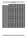
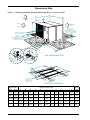
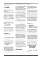
Precision Cooling
For Business-Critical Continuity
Liebert Process Fluid Chiller™
Technical Data Manual - 1.5 - 10 Tons, 50 & 60Hz
TABLE OF CONTENTS
THE LIEBERT PROCESS FLUID CHILLER . . . . . . . . . . . . . . . . . . . . . . . . . . . . . . . . . . . . . . . . . . 1
Standard Features . . . . . . . . . . . . . . . . . . . . . . . . . . . . . . . . . . . . . . . . . . . . . . . . . . . . . . . . . . . . . . . . . 2
Factory-Installed Options . . . . . . . . . . . . . . . . . . . . . . . . . . . . . . . . . . . . . . . . . . . . . . . . . . . . . . . . . . . 2
Optional System Accessories (Field-Installed). . . . . . . . . . . . . . . . . . . . . . . . . . . . . . . . . . . . . . . . . . . 3
Technical Data . . . . . . . . . . . . . . . . . . . . . . . . . . . . . . . . . . . . . . . . . . . . . . . . . . . . . . . . . . . . . . . . . . . 4
Dimensional Data . . . . . . . . . . . . . . . . . . . . . . . . . . . . . . . . . . . . . . . . . . . . . . . . . . . . . . . . . . . . . . . . . 6
Electrical Field Connections . . . . . . . . . . . . . . . . . . . . . . . . . . . . . . . . . . . . . . . . . . . . . . . . . . . . . . . . 12
Electrical Data. . . . . . . . . . . . . . . . . . . . . . . . . . . . . . . . . . . . . . . . . . . . . . . . . . . . . . . . . . . . . . . . . . . 14
Accessories . . . . . . . . . . . . . . . . . . . . . . . . . . . . . . . . . . . . . . . . . . . . . . . . . . . . . . . . . . . . . . . . . . . . . 16
Chiller Selection Form . . . . . . . . . . . . . . . . . . . . . . . . . . . . . . . . . . . . . . . . . . . . . . . . . . . . . . . . . . . . 20
GUIDE SPECIFICATIONS, 1.5 TO 10 TON PROCESS FLUID CHILLER . . . . . . . . . . . . . . . . . . . . . 21
FIGURES
Figure 1
Figure 2
Figure 3
Figure 4
Figure 5
Figure 6
Figure 7
Figure 8
Figure 9
Figure 10
Figure 11
Figure 12
Figure 13
Figure 14
Cabinet size and floor planning dimensional data, 1.5 - 5 ton air cooled . . . . . . . . . . . . . . . . . 6
Cabinet size and floor planning dimensional data, 1.5 - 5 ton air-cooled models with
thermal storage tank . . . . . . . . . . . . . . . . . . . . . . . . . . . . . . . . . . . . . . . . . . . . . . . . . . . . . . . . . . 7
Cabinet and floor planning dimensional data, 8-10 ton air cooled. . . . . . . . . . . . . . . . . . . . . . . 8
Cabinet and floor planning dimensional data, 8-10 ton air cooled with thermal storage
tank cabinet. . . . . . . . . . . . . . . . . . . . . . . . . . . . . . . . . . . . . . . . . . . . . . . . . . . . . . . . . . . . . . . . . . 9
General piping arrangement, 1.5 to 5 ton, air cooled . . . . . . . . . . . . . . . . . . . . . . . . . . . . . . . . 10
General piping arrangement, 8 to 10 ton, air cooled. . . . . . . . . . . . . . . . . . . . . . . . . . . . . . . . . 11
Electrical field connections, 1.5 - 5 ton air cooled . . . . . . . . . . . . . . . . . . . . . . . . . . . . . . . . . . . 12
Electrical field connections, 8-10 ton air cooled . . . . . . . . . . . . . . . . . . . . . . . . . . . . . . . . . . . . 13
Process chiller pump performance—60Hz. . . . . . . . . . . . . . . . . . . . . . . . . . . . . . . . . . . . . . . . . 15
Emergency water switchover—optional . . . . . . . . . . . . . . . . . . . . . . . . . . . . . . . . . . . . . . . . . . 16
Wall-mounted monitoring box—optional. . . . . . . . . . . . . . . . . . . . . . . . . . . . . . . . . . . . . . . . . . 17
Internal piping diagram of wall-mounted monitoring box . . . . . . . . . . . . . . . . . . . . . . . . . . . . 17
Water level control module—optional . . . . . . . . . . . . . . . . . . . . . . . . . . . . . . . . . . . . . . . . . . . . 18
Typical piping arrangement using optional emergency water switchover and water
level control . . . . . . . . . . . . . . . . . . . . . . . . . . . . . . . . . . . . . . . . . . . . . . . . . . . . . . . . . . . . . . . . . 19
TABLES
Table 1
Table 2
Table 3
Table 4
Table 5
Table 6
Table 7
Table 8
Table 9
Table 10
Table 11
Table 12
Table 13
Model number breakdown . . . . . . . . . . . . . . . . . . . . . . . . . . . . . . . . . . . . . . . . . . . . . . . . . . . . . . 1
Air-cooled data—60Hz . . . . . . . . . . . . . . . . . . . . . . . . . . . . . . . . . . . . . . . . . . . . . . . . . . . . . . . . . 4
Air-cooled data—50Hz . . . . . . . . . . . . . . . . . . . . . . . . . . . . . . . . . . . . . . . . . . . . . . . . . . . . . . . . . 5
Dimensional data, 8-10 ton air-cooled . . . . . . . . . . . . . . . . . . . . . . . . . . . . . . . . . . . . . . . . . . . . . 8
Dimensional data, 8-10 ton air-cooled models with thermal storage tank cabinet. . . . . . . . . . 9
Electrical data—60Hz. . . . . . . . . . . . . . . . . . . . . . . . . . . . . . . . . . . . . . . . . . . . . . . . . . . . . . . . . 14
Electrical data—50Hz. . . . . . . . . . . . . . . . . . . . . . . . . . . . . . . . . . . . . . . . . . . . . . . . . . . . . . . . . 14
Emergency water switchover (EWS) Data . . . . . . . . . . . . . . . . . . . . . . . . . . . . . . . . . . . . . . . . 16
EWS electrical data—EWS05, EWS10 and EWS20 . . . . . . . . . . . . . . . . . . . . . . . . . . . . . . . . . 16
Clearance requirements . . . . . . . . . . . . . . . . . . . . . . . . . . . . . . . . . . . . . . . . . . . . . . . . . . . . . . . 16
Wall-mounted monitoring box specifications . . . . . . . . . . . . . . . . . . . . . . . . . . . . . . . . . . . . . . 17
Clearance requirements . . . . . . . . . . . . . . . . . . . . . . . . . . . . . . . . . . . . . . . . . . . . . . . . . . . . . . . 17
Water level control module electrical data . . . . . . . . . . . . . . . . . . . . . . . . . . . . . . . . . . . . . . . . 18
i
THE LIEBERT PROCESS FLUID CHILLER
In addition, the Process Fluid
Chiller is easy to install, requiring only final piping and wiring
connections for proper operation.
Water cooled electronic equipment has special needs beyond
cool water. Sensitive equipment
requires year-round operation,
precise temperature-regulated
water flow and a clean circulating loop—features only available with an equipmentmatched, dedicated chiller. For
best reliability, this chiller
should be factory-tested and
supported.
Built-in quality, along with Liebert’s leadership role in supporting critical electronic systems,
make the Process Fluid Chiller
the logical choice to support
your water-cooled equipment.
The Process Fluid Chiller is
available in capacities to accommodate a variety of sensitive
equipment:
Liebert Process Fluid Chillers
are matched to the application
to provide the proper temperature and flow rate for a variety
of sensitive electronic systems.
PS
Injection Molding Machines
Vacuum Systems and Evaporators
Computers and Semiconductors
Water Jacketed Machinery
Plastics Molding and Extrusion
Metal Working and Plating
Chemical Processes
Laser Welding and Cutting
Distillation Processes
Vapor Degreasers
Power Supplies
Power Transformers
Air/Gas Compressors
Water cooled loads to 10 tons
Medical
MRIs
CAT Scans
PET Scans
Linear Accelerators
CGR and RDS Cyclotron
Electron Microscopes
Gas Chromatograph
Cryogenic Compressors and other
sensitive medical systems
These dedicated chillers are
tested at the factory to ensure
proper operation and are supported by factory-trained
experts with immediate access
to common spare parts.
Table 1
Industrial
Model number breakdown
036
PS = Process Normal capacity
Chiller
in thousand
BTUH
A
P
B
A = Air
Cooled
A = 460
3-phase
S = Stainless Steel
Pump
P = 208/230
1-phase
B = Gauge/Heater/SS
Pump
Y = 20/230
3-phase
M = Multistage Pump
(8/10 ton models)
3
0
3 = Revision
Level
0 = No Tank
T = 100 gal.
Tank
R = Gauge/Heater/
Multistage Pump
(8/10 ton models)
1
Standard Features
Frame and Panels
Refrigerant Dehydrator
The unit base is heavy-gauge
galvanized steel. The exterior
panels are painted and provide
a durable, weather-resistant finish.
The refrigerant dehydrator
assures a moisture-free refrigerant system for extended component life.
Indoor or Outdoor
Installation
The weatherproof panels and
rugged components are durable
for placement outdoors. Circulating fluid may be specified
with propylene or ethylene glycol to adapt the unit to cold climates.
Compressor
The compressor is a fully hermetic, reciprocating design with
overload protection. It has rubber isolated mounting to reduce
noise and vibration. A liquid
line sight glass/moisture indicator is included as well as a manual reset high-pressure switch.
The high-efficiency scroll compressors are standard on 4-ton,
8-ton, and 10-ton models.
Expansion Valve
The externally equalized thermostatic expansion valve
smoothly controls refrigerant
flow and provides precise control of superheat.
Refrigerant Receiver
The refrigerant receiver provides a liquid seal and storage of
refrigerant when the system is
operating in ambients from
minus 30°F to plus 115°F
(-34°C to +46°C). Performance
will be reduced above 95°F
ambient. Consult factory for derated capacities.
Stainless Steel Pump
To provide a non-ferrous circulating loop to protect sensitive
electronics, a pump with a stainless steel housing and impeller
is part of the design.
Fluid Pressure Relief Valve
The 3/4" (2 cm) FPT brass, high
pressure relief valve is mounted
on the inlet pipe to the fluid reservoir expansion tank for safety
protection against system pressures over 50 psi (345 kPa).
Fluid Reservoir Expansion
Tank
The fluid reservoir expansion
tank is manufactured of
14 gauge stainless steel, and
provides thermal storage to act
as a buffer for rapid load
changes and to provide an area
for fluid expansion. Expansion
volume is one gallon (3.8 liters);
maximum working pressure is
50 psi (345 kPa).
Refrigerant Pressure Relief
Valve
A relief valve mounted on the
receiver protects the refrigerant
circuit from high pressure situations.
Control System
This module contains controls
for fluid temperature, refrigerant low pressure switch, manual
reset high pressure switch, low
ambient start relay, compressor
anti-recycle relay, transformer
with circuit breaker and remote
shutdown.
Factory-Installed Options
Refrigerant Gauges
Tank Heater
Fluid Thermal Storage Tank
For at-a-glance monitoring, suction and discharge refrigerant
gauges with large dial faces are
conveniently mounted on the
unit exterior. These gauges are
stainless steel for durability.
(Sold only with tank heater).
An optional copper sheath/stainless steel insertion heater maintains minimum fluid
temperature during low ambient conditions. (Sold only with
refrigerant gauges).
The insulated, stainless steel
tank is built into a frame with
panels, and is factory mounted
and piped below the chiller cabinet. The tank is 50 gallons (190
liters) on 3-5 ton models, and
100 gallons (380 liters) on 8 and
10-ton models.
Multistage Pump
(8 and 10-ton models)
This optional pump provides up
to 200 ft (597 kPa) of head pressure at 15 gpm (57 lpm). See
Figure 9 - Process chiller
pump performance—60Hz.
2
See drawings in “Dimensional
Data” on page -6.
Optional System Accessories (Field-Installed)
Fluid Pressure Gauge
Isolation Ball Valve
A 2 ½ inch (6.35 cm) analog
gauge for monitoring supply or
return pressure is available.
The readout is dual scale: 0 to
100 PSI and 0 to 7 BAR.
An available brass, ¼ turn isolation valve provides for isolation
of fluid piping components in
the event of a service necessity.
Dial Thermometer
To provide supply or return
fluid temperature measurement, a hermetically sealed dial
thermometer is available. The
externally adjustable, 2 ½ inch
(6.35 cm) dial is scaled from 20
to 130°F (-6.7 to 54.4°C).
Check Valve
A brass, swing check valve is
offered for installation in the
chiller outlet piping to prevent
backflow through the chiller.
Circuit Setter
This is a calibrated balancing
valve that, when installed in the
chiller outlet piping, provides
for flow balance, flow metering
and shut off of fluid flow.
Water Level Control and
Alarm System
This module automatically adds
water to the thermal storage
reservoir when the water level
drops below a preset level. It
consists of an on/off switch, a 24
VAC control transformer protected by a circuit breaker, a
flow regulating solenoid valve, a
double check backflow preventer
and time delay relays. The module also includes a prewired
RCM4 monitor with local display and non-powered common
alarm contracts.
!
High Temperature
Thermostat
A remote bulb, adjustable (4090°F, 4.4-32°C) thermostat provides alarm contact when the
fluid temperature rises above a
design limit of system operation.
(See Monitoring and Alarms section for RCM8 Monitoring System).
Low Flow Switch
A flow switch provides set point
and alarm contact when fluid
flow falls below a design limit of
system operation. (See Monitoring and Alarms section for
RCM8 Monitoring System.)
Wall-Mounted Monitoring
Box
This unit includes supply and
return ball valves (six total), a
flowmeter, a water filter with
bypass, pressure gauges (supply and return), temperature
gauges (supply and return) and
3/4" barbed connections.
Emergency Water
Switchover Module (for
systems circulating water)
On a high fluid temperature
alarm or loss of fluid flow alarm,
this unit will automatically
switch to emergency water. This
redundant cooling source protects your critical equipment
from potentially damaging high
temperatures or unplanned
shutdown. See WARNING
below.
RCM4 Four-Point Dry Contact Monitor is a four-point,
normally open, dry contact monitoring panel. One Form C, dry
contact common alarm relay
output (rated at 24 VAC, 3 amp)
is provided. The RCM4 requires
24 VAC or 24 VDC power
source. Power supply is not
included. Four red LEDs illuminate on alarm and the alarm
buzzer is silenced by a front
panel switch.
RCM8DO Eight-Point Dry
Contact Monitor is an eightpoint, dry contact input and
eight dry contact output monitoring panel. It is identical to
the RCM8CE, but with the addition of eight normally open
relays (rated at 24 VAC or VDC,
1 amp) that will automatically
energize upon alarm of each corresponding monitoring point.
RCM8CE Eight-Point Dry
Contact Monitor is an eightpoint, normally open or normally closed (individually
selectable) dry contact monitoring panel that can be used:
• as a stand-alone panel.
• to dial out on alarm to a
remote location or numeric/
alphanumeric pager.
• to interface with Liebert
SiteScan centralized monitoring systems.
WARNING
The emergency water source module is for use on systems that circulate water as the
cooling medium. Using this option on a glycol system will dilute the glycol solution during
emergency operation and could damage the environment as well as violate regulations for
disposing of glycol solutions.
3
Technical Data
Table 2
Air-cooled data—60Hz
PS018A
PS024A
PS036A
PS048A
PS060A
PS096A
PS120A
1.5 Tons
2 Tons
3 Tons
4 Tons
5 Tons
8 Tons
10 Tons
Circulating Fluid—Water
Coolant Flow Rate - GPM (L/M)
2.4 (9)
3.3 (12.6)
5.9 (40.7) 11.1 (76.8)
Pressure Drop - PSI (kPa)
Net Cooling Capacity—BTUH (kW)
5.3 (19.8)
7.9 (29.4)
10.2 (38.4)
16 (60.6)
20 (75.8)
5.1 (35.0)
8.1 (55.6)
13.3 (91.8)
8.1 (55.8)
13.2 (91.0)
45°F (7.2°C) LWT
11800 (3.5) 17000 (5.0) 26600 (7.8) 39300(11.5) 51200 (15.0) 77200 (22.6) 91600 (26.8)
50°F (10°C) LWT
13300 (3.9) 19400 (5.7) 29500 (8.6) 42500 (12.4) 57400(16.8) 83600 (24.5) 102400 (30.0)
55°F (12.8°C) LWT
14800 (4.3) 21700 (6.4) 32600 (9.5) 45900 (13.4) 63500 (18.6) 90400 (26.5) 113000 (33.1)
60°F (15.6°C) LWT
16000 (4.7) 23900 (7.0) 35900 (10.5) 49700 (14.6) 69200 (20.3) 97600 (28.6) 122600 (35.9)
Std. Stainless Steel Pump-Hp(kW) 0.75 (0.55) 0.75 (0.55) 0.75 (0.55)
1.0 (0.75)
1.0 (0.75)
Total Head Pressure-PSI (kPa)
46.8 (321)
46.3 (318)
Water Connection Size in. (mm)
Fluid Volume-Gal. (Liter)
41.1 (282)
40.7 (279)
39.8 (273)
3.0 (2.2)
3/4 (19)
3/4 (19)
1 (25)
1 (25)
1 (25)
1-1/4 (32)
1-1/4 (32)
7.1 (26.9)
7.2 (27.3)
9.8 (37.1)
9.9 (37.5)
10.0 (37.9)
12.0 (45.4)
13.0 (49.2)
7.9 (29.4)
10.2 (38.4)
16.0 (60.6)
20.0 (75.8)
11.1 (76.2) 18.0 (124.3) 13.0 (89.6)
17.6 (121.4)
Circulating Fluid—40% Ethylene Glycol
Coolant Flow Rate -GPM (L/M)
2.4 (9)
3.3 (12.6) 5.3 (19.8)
Pressure Drop - PSI (kPa)
8.4 (58.0) 15.7(108.2) 7.0 (48.1)
Net Cooling Capacity—BTUH (kW)
45°F (7.2°C) LWT
3.0 (2.2)
62.3 (429.6) 60.6 (417.8)
10700 (3.1) 16600 (4.9) 23800 (7.0) 36300 (10.6) 47100 (13.8) 71200 (20.8) 84700 (24.8)
50°F (10°C) LWT
12200(3.6) 18600 (5.4) 26600 (7.8) 39600(11.6) 54200 (15.9) 77800 (22.8) 92600 (27.1)
55°F (12.8°C) LWT
13700 (4.0) 21500 (6.3) 29500 (8.6) 43100 (12.6) 59100 (17.3) 84800 (24.8) 104000 (30.5)
60°F (15.6°C) LWT
15200 (4.5) 23700 (6.9) 32500 (9.5) 48800(14.3) 64000 (18.7) 96200 (28.2) 114000 (33.4)
Std. Stainless SteelPump-Hp(kW) 0.75 (0.55) 0.75 (0.55) 0.75 (0.55)
Total Head Pressure-PSI (kPa)
Water Connection Size - in. (mm)
Fluid Volume - Gal. (Liter)
1.0 (0.75)
1.0 (0.75)
41.1 (282)
40.7 (279)
39.8 (273)
46.8 (321)
46.3 (318)
3.0 (3.2)
3.0 (3.2)
3/4 (19)
3/4 (19)
1 (25)
1 (25)
1 (25)
1-1/4 (32)
1-1/4 (32)
7.1 (26.9)
7.2 (27.3)
9.8 (37.1)
9.9 (37.5)
10.0 (37.9)
12.0 (45.4)
13.0 (49.2)
3.2 (12.6)
5.3 (19.8)
7.9 (29.4)
10.2 (38.4)
16.0 (60.6)
20.0 (75.8)
13.2 (91.2) 21.4 (147.7) 13.4 (92.4)
20.5 (141.3)
62.3 (429.6) 60.6 (417.8)
Circulating Fluid—40% Propylene Glycol
Coolant Flow Rate - GPM (L/M)
Pressure Drop - PSI (kPa)
2.4 (9)
10.4 (71.4) 19.2 (132.1) 8.5 (58.2)
Net Cooling Capacity—BTUH (kW)
45°F (7.2°C) LWT
10200 (3.0) 15900 (4.7) 22400 (6.6) 34400 (10.1) 45000 (13.2) 67400 (19.7) 80600 (23.6)
50°F (10°C) LWT
11700 (3.4) 17900 (5.2) 25100 (7.4) 37900 (11.1) 49600 (14.5) 74400 (21.8) 88500 (25.9)
55°F (12.8°C) LWT
13100 (3.8) 19900 (5.8) 28100 (8.2) 41500 (12.2) 54200 (15.9) 81600 (23.9) 96800 (28.3)
60°F (15.6°C) LWT
14700 (4.3) 22000 (6.4) 31000 (9.1) 45100 (13.2) 59200 (17.3) 88800 (26.0) 105400 (30.9)
Std. StainlessSteelPump-Hp(kW)
Total Head Pressure - PSI (kPa)
Water Connection Size - in. (mm)
Fluid Volume - Gal. (Liter)
4
3/4 (19)
3/4 (19)
1 (25)
1 (25)
1 (25)
41.1 (282)
40.7 (279)
39.8 (273)
46.8 (321)
46.3 (318)
1-1/4 (32)
1-1/4 (32)
62.3 (429.6) 60.6 (417.8)
3/4 (19)
3/4 (19)
1 (25)
1 (25)
1 (25)
1-1/4 (32)
1-1/4 (32)
7.1 (26.9)
7.2 (27.3)
9.8 (37.1)
9.9 (37.5)
10.0 (37.9)
12.0 (45.4)
13.0 (49.2)
Table 3
Air-cooled data—50Hz
PS021A
PS028A
PS038A
PS047A
PS059A
1.5 Tons
2 Tons
3 Tons
4 Tons
5 Tons
Coolant Flow Rate - GPM (L/M)
2.5 (9.6)
3.7 (13.8)
5.1 (19.2)
7.9 (30.0)
8.3 (31.2)
Pressure Drop - PSI (kPa)
6.1 (42.1)
12.3 (84.6)
4.9 (33.5)
8.1 (55.6)
10.2 (70.2)
45°F (7.2°C) LWT
12500 (3.7)
18300 (5.4)
25400 (7.4)
39800 (11.7)
41400 (12.1)
50°F (10.0°C) LWT
14000 (4.1)
20900 (6.1)
28100 (8.2)
43300 (12.7)
46700 (13.7)
55°F (12.8°C) LWT
15400 (4.5)
23400 (6.9)
30900 (9.0)
47000 (13.8)
51900 (15.2)
60°F (15.6°C) LWT
16700 (4.9)
26000 (7.6)
33900 (9.9)
51300 (15.0)
56700 (16.6)
Circulating Fluid—Water
Net Cooling Capacity—BTUH (kW)
Stainless Steel Pump - Hp (kW)
1.0 (.75)
1.0 (.75)
1.0 (.75)
1.5 (1.1)
1.5 (1.1)
Total Head Pressure - PSI (kPa)
39.9 (275.1)
39.4 (271.7)
39.0 (268.9)
39.9 (275.1)
39.6 (273.0)
Water Connection Size - In (mm)
Fluid Volume - Gal. (Liter)
3/4 (19)
3/4 (19)
1 (25)
1 (25)
1 (25)
7.1 (26.9)
7.2 (27.3)
9.8 (37.1)
9.9 (37.5)
10.0 (37.9)
Circulating Fluid—40% Ethylene Glycol
Coolant Flow Rate - GPM (L/M)
2.5 (9.6)
3.7 (13.8)
5.1 (19.2)
7.9 (30.0)
8.3 (31.2)
Pressure Drop - PSI (kPa)
8.7 (60.1)
17.2 (118.4)
6.7 (46.3)
11.1 (76.2)
14.0 (96.2)
45°F (7.2°C) LWT
11500 (3.4)
18100 (5.3)
23000 (6.7)
36600 (10.7)
38000 (11.1)
50°F (10.0°C) LWT
13000 (3.8)
20100 (5.9)
25500 (7.5)
40300 (11.8)
41800 (12.2)
55°F (12.8°C) LWT
14500 (4.2)
23400 (6.9)
28100 (8.2)
44000 (12.9)
45700 (13.4)
60°F (15.6°C) LWT
15900 (4.7)
26100 (7.6)
30900 (9.0)
50400 (14.8)
52100 (15.3)
Net Cooling Capacity—BTUH (kW)
Stainless Steel Pump - Hp (kW)
1.0 (0.75)
1.0 (0.75)
1.0 (0.75)
1.5 (1.1)
1.5 (1.1)
Total Head Pressure - PSI (kPa)
39.9 (275.1)
39.4 (271.7)
39.0 (268.9)
39.9 (275.1)
39.6 (273.0)
Water Connection Size
3/4 (19)
3/4 (19)
1 (25)
1 (25)
1 (25)
7.1 (26.9)
7.2 (27.3)
9.8 (37.1)
9.9 (37.5)
10.0 (37.9)
2.5 (9.6)
3.7 (13.8)
5.1 (19.2)
7.9 (30.0)
8.3 (31.2)
10.8 (74.4)
21.0 (144.7)
8.1 (55.9)
13.2 (91.2)
16.6 (114.8)
Fluid Volume - Gal. (Liter)
Circulating Fluid—40% Propylene Glycol
Coolant Flow Rate - GPM (L/M)
Pressure Drop - PSI (kPa)
Net Cooling Capacity—BTUH (kW)
45°F (7.2°C) LWT
10800 (3.2)
17300 (5.1)
21700 (6.4)
34700 (10.2)
36200 (10.6)
50°F (10.0°C) LWT
12300 (3.6)
19400 (5.7)
24200 (7.1)
38300 (11.2)
40100 (11.7)
55°F (12.8°C) LWT
13900 (4.1)
21500 (6.3)
26800 (7.8)
42000 (12.3)
44100 (12.9)
60°F (15.6°C) LWT
15400 (4.5)
23900 (7.0)
26600 (8.7)
46100 (13.5)
48200 (14.1)
Stainless Steel Pump - Hp (kW)
1.0 (0.75)
1.0 (0.75)
1.0 (0.75)
1.5 (1.1)
1.5 (1.1)
Total Head Pressure - PSI (kPa)
39.9 (275.1)
39.4 (271.7)
39.0 (268.9)
39.9 (275.1)
39.6 (273.0)
Water Connection Size
Fluid Volume - Gal. (Liter)
3/4 (19)
3/4 (19)
1 (25)
1 (25)
1 (25)
7.1 (26.9)
7.2 (27.3)
9.8 (37.1)
9.9 (37.5)
10.0 (37.9)
5
Dimensional Data
Figure 1
Cabinet size and floor planning dimensional data, 1.5 - 5 ton air cooled
A
AIRFLOW
IN
B
D
AIRFLOW
OUT
C*
SHADED AREAS
INDICATE A
RECOMMENDED CLEARANCE
FOR COMPONENT REMOVAL,
ACCESS, AND AIR FLOW.
OPTIONAL REFRIGERANT
PRESSURE GAUGES
2"
18"
(457mm) (51mm)
SHADED AREAS
INDICATE A
RECOMMENDED CLEARANCE
FOR COMPONENT REMOVAL,
ACCESS, AND AIR FLOW.
36"
(914mm)
36"
(914mm)
I
I
H
1" MAX.
(25mm)
H
1" NPT
FEMALE TYPICAL
ON MODELS
G
PS036A, PS048A &
PS060A
36"
(914mm)
1" MAX.
(25mm)
3/4" NPT
FEMALE
TYPICAL ON MODELS
PS018A & PS024A
UNIT DIMENSIONAL DATA
G
2"
(51mm)
A
B
J
2"
(51mm)
2"
(51mm)
4"
(102mm)
E
F
K
K
RAILS REST HERE
(CENTER RAIL ON
MODELS PS048A
& PS060A ONLY.)
4"
(102mm)
FOOTPRINT DIMENSIONS
Model Numbers
Weight
(empty)
Dimensional Data In. (mm)
60 Hz
50 Hz
A
B
C
D
E
F
G
H
I
J
K
lb. (kg)
PS018A
PS021A
36
(914)
40-1/16
(1018)
25-1/4
(641)
18
(457)
N/A
27-7/32
(691)
2 (51)
1-3/8
(35)
2-1/4
(57)
8-27/32
(225)
1-15/16
(49)
314
(142)
PS024A
PS028A
36
(914)
40-1/16
(1018)
25-1/4
(641)
18
(457)
N/A
27-7/32
(691)
2 (51)
1-3/8
(35)
2-1/4
(57)
8-27/32
(225)
1-15/16
(49)
344
(156)
PS036A
PS038A
36-1/8
(918)
48-3/16
(1224)
32-1/2
(825)
18
(457)
N/A
34-3/32
(866)
1-7/8
(48)
2 (51)
2-1/2
(64)
10-3/32
(256)
2
(51)
425
(193)
PS048A
PS047A
36-1/8
(918)
53-3/16
(1351)
38-1/2
(978)
18
(457)
24-19/32
(625)
39-3/32
(993)
2-1/2
(64)
2 (51)
2-1/2
(64)
10-3/32
(256)
2
(51)
532
(241)
PS060A
PS059A
36-1/8
(918)
53-3/16
(1351)
38-1/2
(978)
18
(457)
24 19/32
(625)
39-3/32
(993)
2-1/2
(64)
2 (51)
2-1/2
(64)
10 3/32
(256)
2
(51)
582
(287)
* Note: C dimension includes 2" (51mm) tall rail.
6
Figure 2
Cabinet size and floor planning dimensional data, 1.5 - 5 ton air-cooled models with thermal
storage tank
A
B
C
D
AIRFLOW
IN
C*
STANDARD
PS048A
AIRFLOW
OUT
OPTIONAL REFRIGERANT
PRESSURE GAUGES
C
E
C
FACTORY
ASSEMBLED
STORAGE
TANK
CABINET
(SEE
NOTE 1 )
30"
C
C
18"
(457mm)
SHADED AREAS
INDICATE A
RECOMMENDED CLEARANCE
FOR COMPONENT REMOVAL,
ACCESS, AND AIR FLOW.
36"
(914mm)
C
36"
(914mm)
F
F
1" NPT
FEMALE TYPICAL
ON MODELS
G
PS036A, PS048A &
PS060A
SHADED AREAS
INDICATE A
RECOMMENDED CLEARANCE
FOR COMPONENT REMOVAL,
ACCESS, AND AIR FLOW.
H
1" MAX.
(25mm)
H
36"
(914mm)
NOTES:
1" MAX.
(25mm)
3/4" NPT
FEMALE
TYPICAL ON MODELS
PS018A & PS024A
1. SEE SPECIFICATION SHEET FOR GALLON CAPACITY.
G
2.50"
(63.5mm)
(Typ)
A
B
2.50"
(63.5mm)
(Typ)
.75 Dia.
(Typ 4 places)
Mounting Holes
Model
60 Hz
Dimensional Data In. (mm)
Weight
(empty**)
Tank
Cap.
50 Hz
A
B
C
D
E
F
G
H
lb. (kg)
gal. (l)
PS018A
PS021A
36
(914)
40-1/16
(1018)
25-1/4
(641)
18
(457)
54-19/32
(1387)
2-1/4
(57)
2
(51)
1-3/8
(35)
614
(279)
N/A
PS024A
PS028A
36
(914)
40-1/16
(1018)
25-1/4
(641)
18
(457)
54-19/32
(1387)
2-1/4
(57)
2
(51)
1-3/8
(35)
644
(292)
N/A
PS036A
PS038A
36-1/8
(918)
48-3/16
(1224)
32-1/2
(825)
18
(457)
62-1/2
(1588)
2-1/2
(64)
1-7/8
(48)
2
(51)
725
(329)
N/A
PS048A
PS047A
36-1/8
(918)
53-3/16
(1351)
38-1/2
(978)
18
(457)
68-1/2
(1740)
2-1/2
(64)
2-1/2
(64)
2
(51)
832
(377)
50
(189)
PS060A
PS059A
36-1/8
(918)
53-3/16
(1351)
38-1/2
(978)
18
(457)
68-1/2
(1740)
2-1/2
(64)
2-1/2
(64)
2
(51)
882
(400)
50
(189)
* Note: C dimension includes 2" (51mm) tall rail.
** Note: Add weight of fluid for operating weight.
7
Figure 3
Cabinet and floor planning dimensional data, 8-10 ton air cooled
Table 4
Model
Numbers
60 Hz
PS096A
PS120A
8
Dimensional data, 8-10 ton air-cooled
A
B
C
D
Module Weight
(empty)
lbs. (kg.) net
77
(1956)
39-1/4
(997)
38-1/2
(978)
5-1/2
(140)
750
(340)
Dimensional Data in (mm)
Figure 4
Cabinet and floor planning dimensional data, 8-10 ton air cooled with thermal storage tank
cabinet
Table 5
Dimensional data, 8-10 ton air-cooled models with thermal storage tank cabinet
Model
Numbers
60 Hz
PS096A
PS120A
Dimensional Data in (mm)
A
B
C
D
E
77
(1956)
39-1/4
(997)
38-1/2
(978)
5-1/2
(140)
69-1/4
(1759)
Module Weight
(empty*)
lbs (kg)
Storage Tank
Capacity
gal (L)
1170 (531)
100 (380)
* Note: Add weight of fluid for operating weight
9
10
SL-11601 PG 5
Cold
Water
Supply
Warm
Water
Return
Schrader
Valve
Optional
Reservoir
Heater
Sight
Glass
Optional
Fluid
Relief
Valve
Fluid
Relief
Valve
Low
Fluid
Temperature
Control
Evaporator
External
Equalizers
Optional
High Temperature
Thermostat
Cold
Water
Supply
Optional
Fluid Pressure
Gauges
Warm
Water
Return
FIELD PIPING
FACTORY PIPING
SINGLE CIRCUIT SHOWN
Lee-Temp
Receiver
Pressure Balancing
Valve
Check
Valve
1/2"
(12.7mm)
NPT
Pressure
Relief
Valve
Condenser Coil
Head Pressure
Control
Sight Glass
Liquid Line Solenoid Valve
Filter Drier
Compressor
High
Pressure
Switch
*Components are not supplied by Liebert but
are recommended for proper circuit operation
and maintenance.
Temperature
Sensing
Bulb
Service
Access
Ports
Solenoid
Valve
Optional
Pressure
Gauges
Expansion
Valve
Hot Gas
Bypass
Optional Isolation
Optional Ball Valves
Low Flow
Switch
Optional Fluid
Check Valve
Optional
Circuit
Setter
Ball Valve
Circulating
Pump
Schrader
Valve
Ball
Valve
Bypass
Fixed
Orifice
Reservoir
GENERAL PIPING ARRANGEMENT
PROCESS FLUID CHILLER 1 1/2 - 5 TON AIR COOLED MODELS
Figure 5
General piping arrangement, 1.5 to 5 ton, air cooled
REV 1/01
SL-11601 PG 5A
Cold
Water
Supply
Isolation
Ball Valves
Optional
High Temperature
Thermostat
Solenoid
Valve
Cold
Water
Supply
Optional
Fluid Pressure
Gauges
Warm
Water
Return
Expansion
Valve
Hot Gas
Bypass
Optional Isolation
Optional Ball Valves
Low Flow
Switch
Low
Fluid
Temperature
Control
Evaporator
High
Pressure
Switch
Filter Drier
Check
Valve
FIELD PIPING
FACTORY PIPING
Heater
Lee-Temp
Receiver
Pressure Balancing
Valve
Check
Valve
Pressure
Relief
Valve
Condenser Coil
Head Pressure
Control
** SINGLE CIRCUIT SHOWN
Service
Access
Port
Liquid Line Solenoid Valve
Sight Glass
Scroll
Compressor
*Components are not supplied by Liebert but
are recommended for proper circuit operation
and maintenance.
Temperature
Sensing
Bulb
Optional
Pressure
Gauges
Suction Accumulator
** To Second
Refrigeration System
External
Equalizers
Evaporator
Ball
Valve
Optional Fluid
Check Valve
Optional
Circuit
Setter
Bypass
Fixed
Orifice
Circulating
Pump
Schrader
Valve
Ball
Valve
Optional
Fluid
Relief
Valve
Bypass
Ball Valve
Schrader
Valve
Warm
Water
Return
Circuit
Setter
Optional
Reservoir
Heater
Sight
Glass
Reservoir
Ball Valve
(For adjustment
evaporator flows)
Schrader
Valve
Fluid
Relief
Valve
GENERAL PIPING ARRANGEMENT
PROCESS FLUID CHILLER 8-10 TON AIR COOLED MODELS
Figure 6
General piping arrangement, 8 to 10 ton, air cooled
NEW 01/01
11
Electrical Field Connections
Figure 7
Electrical field connections, 1.5 - 5 ton air cooled
Field supplied unit disconnect switch
recommended within sight of unit.
Single or three phase electrical service
not by Liebert.
Optional field supplied 24V NEC
Class 2 control wiring.
Factory wired to components
on electrical panels.
High pressure switch reset button.
Line voltage connection block.
High voltage electric power
supply entrance.
Remote Unit Shutdown 37 & 38.
Replace existing jumper between
terminals 37 & 38 with normally
closed non powered switch, having
a minimum 75 VA rating. Use field
supplied 24 V Class 2 wiring.
Low voltage control wiring
entrance.
Earth ground connection.
NOTE: Refer to specification sheet for full load amp. and wire size amp. ratings.
!
12
WARNING
Potentially lethal voltages exist within this equipment during operation. Observe all
cautions and warnings on unit and in this manual. Failure to do so could result in serious
injury or death. Only qualified service and maintenance personnel should work with this
equipment.
Figure 8
Electrical field connections, 8-10 ton air cooled
!
WARNING
Potentially lethal voltages exist within this equipment during operation. Observe all
cautions and warnings on unit and in this manual. Failure to do so could result in serious
injury or death. Only qualified service and maintenance personnel should work with this
equipment.
13
Electrical Data
Table 6
Electrical data—60Hz
Stainless Steel Pump (Standard)
With Heater
Tons
Without Heater
Model
Voltage
FLA
WSA
OPD
FLA
WSA
OPD
1-1/2
PS018A
208/230, 1 Phase
16.7
19.1
25
15.7
18.1
25
2
PS024A
208/230, 1 Phase
18.0
20.7
30
17.0
19.7
30
PS036A
208/230, 1 Phase
22.6
26.5
40
21.7
25.6
40
PS036A
208/230, 3 Phase
15.9
18.6
25
14.9
17.6
25
3
4
5
8
10
Table 7
PS036A
460, 3 Phase
8.6
10.1
15
8.0
9.5
15
PS048A
208/230, 3 Phase
21.1
24.5
35
20.1
23.5
35
PS048A
460, 3 Phase
11.3
13.2
20
10.7
12.6
20
PS060A
208/230, 3 Phase
26.8
31.6
50
25.8
30.6
45
PS060A
460, 3 Phase
12.6
14.8
20
12.0
14.2
20
PS096A
208/230. 3 Phase
38.6
42.0
50
37.6
41.0
50
PS096A
460, 3 Phase
20.4
22.3
30
19.8
21.7
25
PS120A
208/230, 3 Phase
49.3
53.6
70
48.3
52.6
70
PS120A
460, 3 Phase
25.0
27.7
35
24.4
26.7
35
Electrical data—50Hz
Stainless Steel Pump (Standard)
With Heater
Tons
1-1/2
2
3
4
5
14
Without Heater
Model
Voltage
FLA
WSA
FLA
WSA
PS021A
200/230, 1 Phase
21.8
24.7
20.8
23.7
PS028A
200/230, 1 Phase
26.8
30.9
25.8
29.9
PS038A
200/230, 1 Phase
29.5
34.3
28.5
33.3
PS038A
200/230, 3 Phase
20.6
24.2
19.6
23.2
PS038A
380/420, 3 Phase
9.9
11.6
9.3
11.0
PS047A
200/230, 3 Phase
29.3
34.1
28.3
33.1
PS047A
380/420, 3 Phase
15.0
17.5
14.4
16.9
PS059A
200/230, 3 Phase
31.4
36.8
30.4
35.8
PS059A
380/420, 3 Phase
14.6
17.0
14.0
16.4
Figure 9
Process chiller pump performance—60Hz
300
2 hp (multistage)
250
Total Head - Ft
200
150
3 hp (single stage)
100
1 hp (single stage)
50
3/4 hp (single stage)
0
0
10
20
30
40
50
60
Flow Rate - GPM
15
Accessories
Figure 10 Emergency water switchover—optional
Power switch
Power Switch
Toggle
switch
Toggle
Switch
Push
Pushbutton
Button
Temperature
display
Temperature Display
Copper
Copper
Piping
piping
Temperature
Temperature
set point
button
Set Poin
t Button
Valve
handle
Valve Handle
Pressure
gauge
Pressu
re Gauge
36"
36.00
18"
22.5"
6"
6"
6"
4.5"
1.25"
33"
.00
3"
8"
8"
4.5"
4.50
8"
33"
.00
112"
2.00
330"
0.00
RIGHT
Table 8
REAR
LEFT
Emergency water switchover (EWS) Data
EWS Model Number
EWS05
EWS10
EWS20
Nominal Flow Rate - GPM (l/m)
Pressure Drop - Ft of water (kPa)
Minimum Flow Setting (adj) - GPM (l/m)
Maximum System Pressure - PSI (kPa)
Connections
A Supply from Chiller
B From Emergency Water Source
C To Open Drain
D Return to Chiller
E Supply to Load
F Return from load
5 (19)
8.0 (23)
1.5 (5.7)
100 (125)
NPT male
3/4"
3/4"
3/4"
3/4"
3/4"
3/4"
10 (38)
14.0 (41)
4.2 (16.0)
100 (125)
NPT male
1"
3/4"
3/4"
1"
1"
1"
20 (76)
15.2 (44.5)
5.8 (22.0)
100 (689)
NPT male
1-1/4”
3/4”
3/4”
1-1/4”
1-1/4”
1-1/4”
NOTE
1. EWS is not for use with glycol systems.
2. The drain line must be piped to an open drain for the valve to operate properly.
3. Water pressure required must be greater than the sum of the EWS pressure drop,
piping pressure drop, and load pressure drop
Table 9
EWS electrical data—EWS05, EWS10 and EWS20
120V / 60 Hz
220V / 50 Hz
Input Amps
Input Voltage
0.6A
0.8A
Maximum Supply Circuit Ampacity
0.7A
1.0A
Maximum Fuse or Circuit Breaker Size
15A
15A
Table 10
Clearance requirements
Top: 24"
Left: 12"
Right: 24"
Front: 36"
16
Figure 11 Wall-mounted monitoring box—optional
Flow
meter
Flow M
eter
Pressure
Pressure Gauges
gauges
36"
36.00
18"
22.5"
Pressure
Pressure Gauges
gauges
4.5"
1.25"
3"
Piping
Piping Cconnections
onnections
8"
8"
PPiping
iping Connections
18"
connections
4.5"
3"
3.00
8"
12"
12.00
30"
30.00
RIGHT
RIGHT
Table 11
LEFT
REAR
REAR
Wall-mounted monitoring box specifications
Flowmeter Range
Water Filter (max flow = 30 gpm)
2-22 gpm
100 microns
Nominal Flow Rating
Pressure Drop @ 15 gpm (57 I/m)
Pressure Gauge Range
Temperature Gauge Range
Connections to Chiller
Connections to Load
15 gpm (57 I/m)
19.6 ft (59 kPa)
0-150 psi
30-160°F
3/4" NPT
1" hose barb
Table 12
LEFT
Clearance requirements
Top:
Left:
Right:
Front:
24"
12"
24"
36"
Figure 12 Internal piping diagram of wall-mounted monitoring box
Ball
Ball Valve
valve
Ball
valve
Ball Valve
Supply
Supply
from Fchiller
romChiller
Supply
Supply
to
load
To L
oad
Fluid
filter
Fluid Filter
Ball
valve
Ball Valve
Flow
meter
F
low Meter
Ball
valve
Ball Valve
Pressure gauge
Pressure Gauge
Return
Return
to chiller
Dial
thermometer
Dial Therm
ometer
Pressure Gaugegauge
Pressure
Dial
Dial Thermometer
thermometer
Return
from load
R
eturn
FromLoad
to Chiller
Ball V
alve
Ball
valve
Ball V
alve
Ball
valve
17
Figure 13 Water level control module—optional
Piping
connections
Piping
Connections
Power
switch
Pow
er Switch
8.0"
2.0"
2.8"
8.0"
Wiring
Wiringconnections
Connections
8.0"
12.0"
12.00
3.92"
3.923.06"
3.06
2.0"
2.00
3.38"
3.38
8.0"
30.0"
30.00
RIGHT
RIGHT
12.0"
12.00
LEFT
LEFT
REAR
REAR
12"
12.0"
Shaded areas indicate
a recommended
clearance
SHADEDAREASINDIC
ATEA
for component
RECOMMENDEDCremoval
LEARANCE
and F
access
ORCOMPONENT REMOVAL
ANDACCESS.
24"
24.0"
24.0"
24"
36.0"
36"
Table 13
Water level control module electrical data
115V (60Hz)
220V (50 Hz)
Input Amps
0.5A
0.4A
Maximum Supply
Circuit Ampacity
0.6A
0.5A
Maximum Fuse or
Circuit Breaker Size
15A
15A
Input Voltage
18
Figure 14 Typical piping arrangement using optional emergency water switchover and water level
control
ter
Ra
yTEW
itA
W
C
CITY
ler
eroll
t
v
n
oe
erl LC er
Letve troll
a
r
e
tW n
Wa Co
ce
your
rcS
n
e
e
e
t
ga urc
rW
e
o
y
c
n er S
gem
rE
t
Eme Wa
D
LOA
ad
Lo
Drain
DRAIN
sr
esille
osscChller
r
Pe i
roc Ch
P
INIndoor
DOOR(Water-Only)
(WATER-ONApplication
LY) APPLICATION
Water
Feed
Water Feed
to
to
Evaporator
Evaporator
Inlet Line
Inlet Line
19
CHILLER SELECTION FORM
Gathering and providing the information on this form will help determine the chiller and options needed
to provide satisfactory performance. Fill out the form and send to a local Liebert representative.
Manufacturer / Model # of equipment
Maximum load - BTU/hr
Minimum load - BTU/hr
Yes / No
to
Load step-change?
Flow rate range - GPM
Desired flow rate - GPM
to
Min/Max leaving water temperature - °F
Desired leaving water temperature - °F
Pressure drop through load - PSI
Maximum rate of change (temperature) - °F/ minute
%
Fluid type, % concentration
Yes / No
Non-ferrous loop required?
Estimated system volume - Gallons
Design ambient - °F
Elevation - Feet above sea level
ADDITIONAL COMMENTS:
20
GUIDE SPECIFICATIONS, 1.5 TO 10 TON PROCESS FLUID CHILLER
1.0 GENERAL
1.1 Summary
These specifications describe
requirements for a self-contained air-cooled process fluid
chiller system.
1.2 Design Requirements
The chiller shall be a Liebert
model______, self-contained aircooled chiller system. Each system shall have a net cooling
capacity of______BTU/HR (kW),
based on a leaving coolant fluid
temperature of_____ °F (°C), and
95°F ambient air temperature.
The cooling fluid shall be____%
propylene glycol, ethylene glycol, or water. Unit is to be supplied with ____volts, _____ph,
_____Hz power supply.
1.3 Submittals
Submittals shall be provided
with the proposal and shall
include: Single-line Diagrams;
Dimensional, electrical, and
capacity data; Piping and Electrical Connection Drawings.
2.0 PRODUCT
2.1 Cabinet and Frame
Construction
The cabinet and chassis shall be
constructed of painted weatherized steel. Removable access
panels shall open to a second
cover that protects all line voltage components. Service access
shall be provided on two sides.
2.2 Coolant Delivery
System
The chiller shall have a factory
installed close-coupled centrifugal pump with a ball bearing
motor designed for continuous
duty. The circulating pump shall
be_____HP and shall have a 304
stainless steel housing and
impeller. The pump shall
provide___GPM (l/m) at___feet
of water (kPa) total head. The
internal coolant delivery system
shall include isolating ball
valves on each side of the pump,
stainless steel thermal storage
reservoir with sight glass, pressure relief valve and optional
heater. The system shall also
include Schrader valve fittings
on each side of the pump and on
each side of the thermal storage
reservoir, and a fixed orifice
bypass to prevent pump “dead
heading”. Internal chilled water
piping shall be factory insulated.
2.3 Refrigeration System
The refrigeration system shall
be direct expansion with fully
insulated shell and coil evaporator. The system shall include
service ports, liquid line filter
dryer, refrigerant sight glass
and moisture indicator. The system shall also include an adjustable, externally equalized
expansion valve, liquid line solenoid valve, and an adjustable
hot gas bypass with a solenoid
valve for compressor capacity
control. The internal condensing
unit shall be factory tested and
charged with refrigerant (R-22)
and shall include a direct-drive
propeller-type fan. The condenser coil shall be constructed
of copper tubes and aluminum
fins. The winter control system
shall be a Liebert “Lee-Temp”
system to allow start-up and
positive head pressure control
with ambient temperatures as
low as –30°F (-34.4°C). The LeeTemp package shall include
insulated receiver, pressure
relief valve, check valve, and
head pressure three-way control
valve. No piping, brazing, dehydration or charging of the refrigeration system shall be
required.
2.4 Compressor
The unit shall have a (hermetic)
(scroll) compressor(s) with suction gas cooled motor, vibration
isolators, thermal overloads,
crankcase heater, and shall
operate at 3500 RPM @ 60 Hz.
2.5 Control System
The control system shall consist
of a fluid temperature control,
refrigerant pump down low
pressure switch, manual reset
high pressure switch, low ambient start relay, compressor antirecycle relay set for three minutes, 24 volt transformer with
circuit breaker, and remote shut
down terminals for unit shutdown via a maintained NC contact. The line voltage system
shall include pump contactor,
pump overload relay, compressor/fan contractors, and starters.
3.0 OPTIONAL
EQUIPMENT
3.1 Refrigerant Gauges
and Reservoir Heater
The refrigerant gauges and reservoir heater shall be factory
installed. The reservoir heater
shall maintain minimum fluid
temperature during low ambient conditions and shall be a
250-watt, copper sheath/stainless steel plug insertion type
heater with integral adjustable
thermostat for the fluid reservoir. The adjustable thermostat
shall be set to turn on at 35°F
(1.7°C) and turn off at 42°F
(5.6°C). The suction and discharge refrigerant gauges shall
be 2 ½ inches (63.5 mm) in
diameter, hermetically sealed,
with stainless steel bourdon
tube and stainless steel housing.
3.2 Multistage Pump
(option on 8- and
10-ton models)
Chiller shall include a 6-stage
2 Hp pump capable of delivering
____ GPM at _____ Ft. of Total
Head.
21
3.3 Storage Tank
System shall include a ____ gallon stainless-steel storage tank,
factory piped, and installed
beneath the chiller cabinet.
4.0 ACCESSORIES
4.1 Emergency Water
Switchover Module
This module shall automatically switch to emergency (city)
water on either a high fluid temperature alarm or loss of fluid
flow alarm. This module shall be
a pre-piped and wired assembly
that consists of an enclosure,
RCM4 monitor, on/off switch, 24
VAC control transformer protected by a circuit breaker, nonpowered alarm contacts, auto/
manual override switch, reset
switch, time delays, flow switch,
and high temperature thermostat. The system shall also
include two ball valves, two
three way solenoid valves, double check backflow preventer,
circuit setter on the drain line, a
fluid pressure gauge and valve,
and a dial thermometer on the
entering fluid line. It shall
require a 120 VAC, 60 Hz, single
phase power input.
Note: This module must not be
used on systems that circulate
glycol as the cooling medium.
4.2 Water Level Control
and Alarm System
The chiller shall have a water
level control and alarm system
that shall automatically add
water to the thermal storage
reservoir when the water level
drops below a preset level. An
alarm circuit shall activate if
the tank has not filled after a
preset time period of four minutes, and a lock out circuit shall
de-energize the solenoid valve
with integral strainer, double
check backflow preventer, flow
regulating valve, automatic air
vent, and time delay relays.
The module shall also include a
pre-wired RCM4 monitor with a
22
local display for high fluid level,
low fluid level, fluid fill and fluid
fill lockout, and separate nonpowered contacts for high fluid
level, low fluid level, and fluid
fill, and non-powered common
alarm contacts. The system
shall be field installed. It shall
require 120 VAC, 60 Hz, singlephase power input.
4.3 Fluid Pressure Gauge
A quantity of ________2½ in.
(63.5 mm) dial gauges, suitable
for field panel mounting for supply and/or return pressure measurement shall be provided. The
gauge shall have a scale from 0
to 100 PSIG (0 to 690 kPa), and
black painted steel housing, and
a bourdon tube for monitoring
pressure.
4.4 Check Valve
A brass body and swing check
valve shall be provided for field
installation in the fluid piping to
prevent backflow.
4.5 Dial Thermometer
A quantity of ______2 ½in. (63.5
mm) dial thermometers, suitable
for field panel mounting for supply and/or return fluid temperature measurement shall be
provided. The thermometers shall
have a dual scale from 20°F to
120°F and have -6.7°C to 54.4°C.
4.6 Relief Valve
A brass body valve preset at 50
PSI (344 kPa) shall be provided
for field installation in the fluid
piping.
4.7 Circuit Setter
A bronze body, calibrated balancing valve for flow balance,
metering, and shutoff shall be
provided for field installation.
4.8 Ball Valve
A quantity of _____brass body,
¼ turn ball valves for isolation
of fluid piping components and
serviceability shall be provided
for field installation.
4.9 High Temperature
Thermostat
A remote bulb adjustable thermostat with an adjustable range
from 40°F to 90°F (4.4°C to
32.3°C) shall be provided for field
installation. The thermostat shall
provide a non-powered alarm contact when the fluid temperature
rises above design limit.
4.10 Low Flow Switch
A brass body flow switch shall
be provided for field installation
to provide a non-powered alarm
contact when fluid flow falls
below design limit.
4.11 Wall-Mounted
Monitoring Box
A wall-mounted monitoring box
shall be provided. The box shall
include a flowmeter, 100 micron
filter, four (4) ball valves, supply
and return temperature gauges,
and supply and return pressure
gauges.
5.0 EXECUTION
5.1 Installation of
Process Fluid Chiller
5.1.1
General
Install process fluid chiller in
accordance with the manufacturer’s installation instructions.
Install units plumb and level,
firmly anchored in locations indicated and maintain manufacturer’s recommended clearances.
5.1.2
Electrical Wiring
Install and connect electrical
devices furnished by manufacturer but specified to be field
installed. Furnish copy of manufacturer’s electrical connection
diagram to electrical contractor.
5.1.3
Field Quality Control
Start up process fluid chiller
units in accordance with manufacturer’s start up instructions.
Test controls and demonstrate
compliance with requirements.
Ensuring The High Availability
0f Mission-Critical Data And Applications.
Emerson Network Power, the global leader in enabling business-critical
continuity, ensures network resiliency and adaptability through
a family of technologies—including Liebert power and cooling
technologies—that protect and support business-critical systems.
Liebert solutions employ an adaptive architecture that responds
to changes in criticality, density and capacity. Enterprises benefit
from greater IT system availability, operational flexibility and
reduced capital equipment and operating costs.
Technical Support / Service
Web Site
www.liebert.com
Monitoring
800-222-5877
[email protected]
Outside the US: 614-841-6755
Single-Phase UPS
800-222-5877
[email protected]
Outside the US: 614-841-6755
Three-Phase UPS
800-543-2378
[email protected]
Environmental Systems
800-543-2778
Outside the United States
614-888-0246
Locations
United States
1050 Dearborn Drive
P.O. Box 29186
Columbus, OH 43229
Europe
Via Leonardo Da Vinci 8
Zona Industriale Tognana
35028 Piove Di Sacco (PD) Italy
+39 049 9719 111
Fax: +39 049 5841 257
Asia
7/F, Dah Sing Financial Centre
108 Gloucester Road, Wanchai
Hong Kong
852 2572220
Fax: 852 28029250
While every precaution has been taken to ensure the accuracy
and completeness of this literature, Liebert Corporation assumes no
responsibility and disclaims all liability for damages resulting from use of
this information or for any errors or omissions.
© 2006 Liebert Corporation
All rights reserved throughout the world. Specifications subject to change
without notice.
® Liebert and the Liebert logo are registered trademarks of Liebert
Corporation. All names referred to are trademarks
or registered trademarks of their respective owners.
SL-16510_REV1_08-06
Emerson Network Power.
The global leader in enabling Business-Critical Continuity™.
AC Power Systems
Embedded Computing
Embedded Power
Connectivity
DC Power Systems
Integrated Cabinet Solutions
EmersonNetworkPower.com
Outside Plant
Services
Power Switching & Control
Site Monitoring
Precision Cooling
Surge Protection
Business-Critical Continuity, Emerson Network Power and the Emerson Network Power logo are trademarks and service marks of Emerson Electric Co.
©2006 Emerson Electric Co.