1
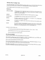
in
I R T Electronics Pty. Ltd. A.C.N. 000 832 575
26 Hotham Parade, ARTARMON. N.S.W. 2064 Australia
National: Phone: (02) 439 3744 Fax (02) 439 7439
International: +61 2 439 3744
+61 1 439 7439
IRT Digital Intercom System
Comprising Types:
AA-332
CP-332
IF-332
CI-332
Central Processor Matrix
Control Panel
2/4 Wire Interface
5 way Camera Interface
Designed and manufactured in Australia
aa-332.ibw
pagelof21
16/08/95
IRT Digital Intercom System
Comprising Types:
AA-332
CP-332
IF-332
CI-332
Central Processor Matrix
Control Panel
2/4 Wire Interface
5 way Camera Interface
Instruction Book
Table of Contents
Section
Page
General description
Technical specifications
Detailed description
Configuration
Software key configuration
Installation
Operational safety
Pre-installation
AA-332 Central processor matrix
TB-332 Dual talkback cards
Control panel wiring
AA-332 Control panels with microphones
4 Wire stations
2 Wire stations
Interrupted foldback
System additions
Connector pinouts
Layout diagrams
Operation
Maintenance & storage
Software maintenance
Hardware maintenance
Storage
Warranty & service
Equipment return
Drawing list index
3
4
5
7
8
9
9
9
10
10
12
12
12
13
13
13
14
16
17
18
18
20
20
20
20
21
This instruction book applies to units later than S/N 9507000.
aa-332.ibw
page 2 of 21
16/08/95
GENERAL DESCRIPTION
The AA-332 digital intercom system is intended to provide the type of intercom talkback facilities frequently
required in broadcast studios or production houses.
The system comprises a central processing frame to which each station is connected by a twisted pair of wires in a
star configuration.
Overall operation and control of the system is determined by a microprocessor in the AA-332 central control unit
which may be programmed by the user for specific key functions for each connected station. The programming of
the system may be changed at any time by simply connecting a PC to the central unit and re-programming the
microprocessor using the software provided.
The software controlled key assignment of each key on each station eliminates the need for custom panels and
allows flexibility as requirements grow or change. Each panel is equipped with a designation strip to indicate the
function of each switch in a manner most suited to the application.
The system features:
•
Adjustable size from 2 to 32 stations.
•
Single pair wiring
•
100% flexibility in switch assignment
•
Re-configure program runs on PC clones
•
2 wire and 4 wire interfaces
•
Unique "Answer" function
•
Call multiple stations with one key
•
"Command to Talk" or "Command to Listen"
•
Non blocking access
•
Provision for Interrupted Foldback
Components that may be included in the system are as follows:
AA-332
Central Processing Unit. (Essential item)
One unit required per system. Comprises a centrally located 3 RU Eurocard rack frame containing
from 1 to 16 Dual Talkback Cards, a Switch Logic Card, a Processor Card and a power supply.
CP-332
Control Panel.
Up to 32 panels may be connected to the AA-332. Each 1 RU panel features a microphone input, a
speaker volume control, 16 three position lever switches and an 'active' LED. On the rear of the panel
are connections for an optional external loudspeaker, a 600 Ohm 0 dBm output line, a 600 Ohm 0
dBm input line and a PTT contact set. Each panel requires 240 Vac for operation.
IF-332
2/4 Wire Interface Panel.
For interface to external lines which do not require local control.
This panel is equivalent to the CP-332, but without switches and microphone input.
CI-332
5 way Camera Interface.
Acts as a mix-minus sub-mixer for 2 to 5 camera style headsets. Each operator receives a mix of the
other operators without his own voice.
May be connected to an IF-332 for interface to the main intercom system. Where a PTT facility is
required this may be connected through to the IF-332 to sustain an intercom connection.
aa-332.ibw
page 3 of 21
16/08/95
TECHNICAL SPECIFICATIONS
Power Requirements:
240 Vac
Power consumption
Other:
Temperature range
Mechanical
Dimensions
0-50° C ambient
Suitable for mounting in 19" with input output and
power connections on the rear panel
Grey enamel, silk screened black lettering & red
IRT logo
1RU
Standard accessories
Matching data connectors.
Optional accessories
Instruction manual
TME-6 module extender card
Finish:
aa-332.ibw
page 4 of 21
16/08/95
DETAILED DESCRIPTION
(See Drawing 803058 - Digital intercom functional block diagram.)
The AA-332 is a 2 to 32 station digital intercom system. It comprises a centrally located 3 RU Eurocard rack frame
central processing unit which controls operation of the overall system.
Connected to this, each by a single screened pair of wires up to 1 Km in length, are from 2 to 32 CP-332 or IF-332
control panels.
All the information between the matrix and a control panel is carried on a single screened pair of wires. The speech
in both directions, the front pane! switch status and the PTT/Busy information is digitally multiplexed and
continually sent in a 'ping-pong' sequence.
Operation of the system is under software control allowing any key on any control panel to effect a connection
between any two control panels.
Each system is supplied with a configuration program which can be run on a PC.
Provided that the full 32 stations are not yet installed the addition of another station merely requires the insertion of
a Dual Talkback Card and the connection of another CP-332 or IF-332 control panel.
AA-332 Central processor matrix:
It comprises a centrally located 3 RU Eurocard rack frame containing from 1 to 16 TB-332 dual talkback cards, an
802954 switch logic card, an 803169 processor card and a power supply.
By connecting the serial port of a PC to the control port on the front of the processor card a complete matrix
configuration can be downloaded in seconds.
This program's prime function is to make key assignment an easy process, but in addition it allows for uploading of
the current configuration from the matrix for editing, the storing of matrix configurations on disk and the retrieval
of other configurations from disk.
Once the configuration has been downloaded it is stored in a 'look-up1 table held in battery backed RAM on the
AA-332 processor card.
For maintenance purposes access to the internal operation of the matrix can also be made through the control port.
IF-332 Control panel:
(See Drawing 803363 sheet 3 - Control panel functional diagram.)
Each 1 RU panel features a front panel volume control and an 'active' LED. On the rear of the panel are two
connectors, one for an optional external loudspeaker and the other containing connections for • the line to the matrix
• a 600 Ohm 0 dBm output line
• a 600 Ohm 0 dBm input line
• a PTT contact set.
Each panel requires 240 Vac for operation.
The IF-332 may be used for interfaces such as 2 or 4 wire external lines which do not require local control, switches
or microphone level input.
The IF-332 may also include a VOX adaptor which may be used to automatically switch the panel to a particular
address when audio input is detected.
aa-332.ibw
page 5 of 21
16/08/95
In addition a special version of the IF-332 (the IF-332/B) is available with an additional connector on the rear panel
which accesses the address lines of the panel so that it may be used with external switches. This allows the
construction of custom panels with only the required number of switches.
The IF-332/B VOX circuit connection is available on the rear panel remote switch connector allowing simple
patching of the VOX to any particular address. This may either be achieved through a remote panel or directly using
a 'D' connector with a shorting link from the VOX output to the desired address pin.
CP-332 Control panel:
(See Drawing 803363 sheet 3 - Control panel functional diagram.)
The CP-332 uses the same internal circuitry as the IF-332 but in addition provides a front panel XLR type
microphone input and 16 three position lever switches.
As each switch on the CP-332 has three positions, it is possible to select a total of 32 addresses. In most systems
however, it is unlikely that a particular panel will have reason to access more than 16 other addresses.
For this reason the switches supplied will normally be locking in the UP position and momentary in the DOWN
position. This allows a more natural key assignment of "press to talk" for the locking position and "monitor" for the
locking position.
Where this switch arrangement is deemed unsuitable the CP-332 may be supplied with switches with a momentary
action in both directions.
If other switch combinations are required consideration should be given to the construction of custom panels using
the IF-332/B described above.
The AMX800 or a similar microphone with integral gooseneck may be plugged directly into the front panel XLR
microphone socket of the CP-332.
aa-332.ibw
page 6 of 21
16/08/95
CONFIGURATION
Key assignment:
Any key on any control panel can be made to effect a connection between any two control panels. To achieve this
there is a 'look-up' table held in battery backed RAM on the Processor Card.
Provided with each system is a Configuration Program which can be run on a PC. By connecting the serial port of
the PC to the Control Port on the front of the Processor Card a complete matrix configuration can be downloaded in
seconds.
This program's prime function is to make key assignment an easy process, but in addition it allows for uploading of
the current configuration from the matrix for editing, the storing of matrix configurations on disk and the retrieval
of other configurations from disk.
For maintenance purposes access to the internal operation of the matrix can also be made through the Control Port.
2 wire/4 wire interfaces:
Each CP-332 Control Panel, in addition to its microphone input and loudspeaker output, has a balanced 0 dBm, 600
Ohm, input and output lines for 4 wire operation. Switching of the direction of the input line may enabled for 2 wire
operation. When ever a control panel is receiving a call a Tush To Talk' (PTT) relay in the panel is operated and the
front panel LED brightens. Contacts on this relay are available for external use (e.g. for keying 2 way radios etc.).
An IF-332 Interface Panel has all the features of a CP-332 except that it has no front panel switches and no
microphone circuit.
Answer:
Through the Configuration Program any key may be assigned the 'Answer' function.
When operated this key does just that. It calls the last station that called you.
Therefor to answer a call the operator does not need to know who it was that called, but merely answers by using
the Answer1 key.
Multiple station calls:
Two methods are provided to cause a key operation to call more than one station.
Firstly, the Configuration Program allows you to set up Groups.
A Group comprises from 2 to 7 switch numbers. Up to eight such Groups may be configured. Once a group has
been configured you may assign a Group to any key/s.
The effect is that operation of that key will call all the stations in that group.
Secondly, each control panel has on its PCB positions to add diodes to 'or' the function of front panel switches.
Command to listen:
The Command To Listen is the reverse assignment of a Command To Talk.
le: if a key on Control Panel 1 is used to call Control Panel 2 its function would be to connect Time Slot 1 to Time
Slot 2, but if it was required to be a 'listen' key it would connect Time Slot 2 to Time Slot 1.
Because you can assign any key to any function Command To Listen is easily achieved.
Non-blocking access:
In a Station Intercom System the fact that someone is already talking to you must not preclude anyone else from
also talking to you. This is called non-blocking access.
The AA-332 allows up to seven people to talk to you at once.
It is considered that any more than this would make for total confusion.
Interrupted foldback:
Each CP-332 or IF-332 has a 0 dBm, high impedance "Foldback* input.
If the control panel is appropriately configured the signal at this input will be heard from the panel loudspeaker
provided that the panel is not being called.
aa-332.ibw
page 7 of 21
16/08/95
Software Key Configur Uioii
A CP-332 Control Panel, unless specially ordered, has 16 three position keys on its front panel. The UP position is
locking and the DOWN position is momentary. The CENTRE position is normally considered as OFF.
You can assign any key on any control panel to turn on any "cross-point".
Definitions:
SWITCH NUMBER
For the purposes of the configuration program the switches are numbered from down to
up, from left to right, starting with the left hand switch down as Switch 1 and the
rightmost switch up as Switch 32.
SOURCE
The Source is the control panel number from which the speech is to originate.
DESTINATION
The Destination is the control panel number which will hear the source.
INVERT
Normally the operation of a switch will turn on a "cross-point". If it is an Invert switch
its operation will turn off the "cross-point".
ANSWER
The operation of an Answer switch will call the last control panel that called the answer
switch's panel.
GROUP
If a switch is assigned a Group Number the operation of the switch will operate all the
switches on its own control panel that are defined in that group. There are a maximum of
eight groups, and each group may have from 2 to 7 switch numbers in it.
Limitations to switch attributes exist.
1) A switch may only have one of the following attributes assigned to it. Invert -Answer - Group.
2) If a switch is an Answer then its source must be its own control panel.
3) A Group switch must not be part of a group.
Use of Invert attribute:
One use of the Invert attribute is when communicating with 2/4-wire circuits.
You may wish to arrange a key so that in its UP position it is 'OFF', in its MIDDLE position you LISTEN to the
2/4-wire circuit and in its DOWN position you TALK to the 2/4-wire circuit.
Here you need to invert the function of the listen position.
This will work satisfactorily provided that the 2/4-wire circuit does not have a microphone/loudspeaker. If it does
you will get 'sing round* as the 'Listen' function is not turned off when you talk.
One solution to this problem is to "wire or' the talk key to the listen key on the control panel PCB. There are places
on the PCB to install diodes. Certain traces must be cut when you do this.
aa-332.ibw
page 8 of 21
16/08/95
INSTALLATION
Unpack the AA-332 central processor matrix frame and control panels and ensure no damage has occurred in
transit.
Operational Safety
WARNING
Operation of electronic equipment involves the use of voltages and currents which
may be dangerous to human life. Maintenance personnel should observe all safety
regulations. Do not change components or make adjustments inside the equipment
with power ON unless proper precautions are observed. Note that under certain
conditions dangerous potentials may exist in some circuits even though power
controls are in the OFF position.
Pre-Installation
Handling:
The modules used in this equipment contain static sensitive devices and proper static free handling precautions
should be observed.
Where individual circuit cards are stored, they should be placed in antistatic bags and proper antistatic procedures
should be followed when inserting or removing cards from these bags.
Power:
Ensure that operating voltage of unit and local AC mains supply voltage match and that correct rating fuse is
installed for local supply.
Earthing:
Chassis earth connection of the equipment is via the earth connection on the three pin AC mains supply input. This
is a safety earth and must be connected.
Signal earth:
All signal earths are connected to chassis earth.
aa-332.ibw
page 9 of 21
16/08/95
AA-332 Centra] processor matrix:
Ensure lhat the power supply has been set for the correct input voltage. Note that there is a fuse in the IEC320 style
power inlet connector on the rear of the matrix as well as one internal to the power supply.
The frame should now be mounted in a standard 19" rack.
The AA-332 Central processor matrix has 18 slots for cards which plug into mating connectors on the motherboard.
These are numbered from left to right looking at the frame from the front.
To access the frame for insertion or removal of cards and for accessing the system for programming purposes,
simply loosen the two retaining screws at the top right and left ends of the perspex cover and allow the cover to
hinge downwards.
Check that the 802954 switch logic card occupies slot 17 in the frame. This card can be identified by a reset button
located on the front of the card.
Check that the 803169 main processor card occupies slot 18 in the frame. This card can be identified by a 20 pin
rectangular PCB connector located on the front of the card. This is the control port connector used for programming
purposes.
Locate the adaptor cable provided with each AA-332 central processor matrix unit which converts this connection
to the RS-232 25 pin D format. Connections to this D' connector are shown on Drawing 803058 sheet 3.
Also on this card is a battery backed RAM. Should the mains supply and the battery both fail the current
configuration will be lost and the Matrix will restart with a default configuration which is a 32 station system with
no Answer key, no Groups and no Inverted function keys. If this occurs replace the battery and download your
configuration via the control port.
TB-332 Dual talkback cards:
Before the system can operate a number of TB-332 dual talkback cards must be fitted to the AA-332 central
processor matrix frame. These occupy the leftmost 16 slots in the frame.
Before inserting the required number of TB-332 cards they must be set to an address indicating the number of the
stations to which they will be connected.
On every TB-332 dual talkback card there is an address switch.
To ensure that the numbering of control panels follows the connector sequence on the rear of the matrix this address
must be set to correspond to the slot into which the dual talkback card is inserted.
The 16 slots number from left to right looking at the front of the frame. The first slot is address 0 HEX and the 16th
slot is address F HEX.
Address 0 controls control panels 1 and 2 and address F controls control panels 31 and 32.
Observing antistatic precautions set the address switches on each TB-332 dual talkback card as required.
aa-332,ibw
page 10 of 21
16/08/95
The card address switches are marked SW 1. 2 x CARD ADDRESS and should be set as follows:
Station #'s
1 &
3 &
5 &
7&
9 &
11 &
13 &
15 &
17 &
19 &
21 &
23 &
25 &
27 &
29 &
31 &
2
4
6
8
10
12
14
16
18
20
22
24
26
28
30
32
Hex Address
0
1
2
3
4
5
6
7
8
9
A
B
C
D
E
F
4
ON
ON
ON
ON
ON
ON
ON
ON
OFF
OFF
OFF
OFF
OFF
OFF
OFF
OFF
Switch positions
3
2
ON
ON
ON
ON
OFF
ON
OFF
ON
OFF
ON
OFF
ON
OFF
OFF
OFF
OFF
ON
ON
ON
ON
ON
OFF
ON
OFF
OFF
ON
OFF
ON
OFF
OFF
OFF
OFF
1
ON
OFF
ON
OFF
ON
OFF
ON
OFF
ON
OFF
ON
OFF
ON
OFF
ON
OFF
TB-332 Dua] Tafkback card
OFF
ON
swi
2xCARD
ADDRESS
Front:
64 pin DIN
Connector
Slide each TB-332 card firmly into position in the frame.
One TB-332 is required for each two stations whether they are CP-332 or IF-332. Any number of TB-332 cards
from 1 to 16 may be fitted at any time.
If an existing system has an odd number of stations it will not be necessary to add another TB-332 when adding
only one additional station.
Conversely, when an existing system has an even number of stations a TB-332 dual talkback card will be required
even if only one station is being added.
The CI-332 cannot make connection directly to the AA-332 and requires an IF-332 to perform this function. Thus
sufficient IF-332's should be included in the overall system to link any required CI-332's to the AA-332 central
processor matrix. These IF-332's must be counted when determining the number of TB-332 cards required in the
AA-332 central processor matrix.
aa-332.ibw
page 11 of 21
16/08/95
Control panel wiring:
Wiring information for both the CP-332 & IF-332 is shown in drawing 803058 sheet 2.
Please note that panels must not be wired in parallel. Each CP-332 or IF-332 must be wired individually back to the
AA-332 central processor matrix.
All the information between the matrix and a control panel is carried on a single screened pair of wires.
The speech in both directions, the front panel switch status and the PTT/Busy information is digitally multiplexed
and continually sent in a 'ping-pong' sequence.
AA-332 Control panels with microphones:
Ensure that the CP-332 panels are the correct type for your mains voltage. Note that there is a fuse in the IEC320
style power inlet connector on the rear of the panel.
If you are using an external loudspeaker open the CP-332 and unplug the internal loudspeaker. (For best clarity we
recommend the use of an external loudspeaker.) There are 5 lid retaining screws, two on each end and one on the
bottom.
Mount the control panels.
Plug a the microphone into the front panel microphone connector. If you are using a AMX800 microphone note that
it has an on/off switch on its connector.
Wire the control panels to the matrix.
4 Wire stations
Either CP-332 or IF-332 control panels may be used for 4- wire operation. Ensure that the CP/IF-332 panels are the
correct type for your mains voltage. Note that there is a fuse in the IEC320 style power inlet connector on the rear
of the panel.
If you use a CP-332 the microphone is not necessary. Open the control panel. There are 5 lid retaining screws, two
on each end and one on the bottom.
Ensure that Link 1 and 3 are removed.
If you require sidetone install Link 2.
Wire PL 1 (the 15 pin D' connector) using shielded pairs as follows:
Incoming speech from 4-wire circuit
PL 1 7 and 14
Shield
PL 1 6
Outgoing speech to 4-wire circuit
Line to Matrix
PL 1 8 and 15
PL 1 1 and 9
Shield
PL 1 2
The Control Panel will send a level of approximately 0 dBm and expects the same level at its input. The send and
receive impedances are both 600 Ohms.
Where a lower send impedance is required (such as when feeding multiple cameras for instance) you may consider
connecting a balancing transformer to the loudspeaker output. If you do it is necessary to set the send level with the
front panel gain control (which in the case of the IF-332 is a screwdriver adjustment).
If the 4-wire circuit requires a Push-To-Talk control it is available on PL 1 12 and 13.
Wire the control panels to the matrix.
aa-332.ibw
page 12 of 21
16/Og/95
2 Wire stations
Either CP-332 or IF-332 control panels may be used for 2- wire operation. Ensure that the CP/IF-332 panels are the
correct type for your mains voltage. Note that there is a fuse in the IEC320 style power inlet connector on the rear
of the panel.
If you use a CP-332 the microphone is not necessary.
Open the control panel. There are 5 lid retaining screws, two on each end and one on the bottom.
Ensure that Link 1 is installed and Link 3 is removed.
If you require sidetone install Link 2.
Wire PL 1 (the 15 pin T>' connector) using shielded pairs as follows:
Incoming/Outgoing speech
Shield
Line to Matrix
Shield
PL 1 7 and 14
PL 1 6
PL 1 1 and 9
LI 2
The control panel will send a level of approximately 0 dBm and expects the same level at its input.
The send and receive impedances are both 600 Ohms.
If the 2-wire circuit requires a Push-To-Talk control it is available on PL 1 12 and 13.
Wire the control panels to the matrix.
Note that although the IF-332 has no switches installed it stil! has the switch scanning circuits. A possible use for
this could be where the 2/4 wire line has an 'RX Unmule' ground signal. This could be wired through an unused pin
of PL 2 to one of the switch positions. A received signal can now be made to call a particular station.
Interrupted Foldback
A balanced 0 dBm signal applied to PL 2 5 and 9 will appear in an unbalanced form at PL 1 3.
If Link 4 is installed this signal will be turned off whenever the panel is called.
By strapping PL 1 3 and 4 this signal will be heard in the loudspeaker (and sent out on the 4-wire send line).
Some preset to the level of this signal can be achieved by replacing the strap with a resistor. For example if the
resistor were 10 K Ohms the signal would be reduced by 6 dB. The input impedance at PL 2 6 and 9 is 20 K Ohms.
Adding to an existing system:
Provided that the full 32 stations are not yet installed the addition of another station merely requires the insertion of
a TB-332 dual talkback card and the connection of another CP-332 or IF-332 control panel.
Before testing the station ensure that the currently loaded software has been set up to allow for the additional panel.
If this is not the case this must be done before the panel will be able to communicate with the remainder of the
system. See configuration section for instructions.
aa-332.ibw
page 13 of 21
16/08/95
Connector pin outs:
AA-332:
Processor card I/O port - 20 pin dual PCB edge connector (male)
1. Signal GND
2. Transmitted data from PC
3. Data to PC
4. CIS from PC
5. RTS to PC
6. Internally connected
7. Protective ground
8- Internally connected
9.
10.
Rear panel SK 1 to SK 32 (each 15 pin 'D' female)
1. Serial data +ve
2. Serial data GND
3.
4.
5.
6.
7.
8.
CP-332:
Rear panel S K I - 9 pin'D'
1. Speaker +ve
2. Speaker GND
3. IFB input -ve
4. IFB input +ve
5.
18. Internally connected
19.
20.
9. Serial data -ve
10.
12.
13.
14.
15.
16.
6.
7.
8.
9.
Rear panel SK 2-15 pin 'D' connector (female)
1. Serial data +ve
2. Serial data GND
3. IFB
4. IFB
5. PTT relay NC
6. 2 Wire line GND
7. 2 Wire line +ve
8. 4 Wire send +ve
aa-332.ibw
11.
12.
13.
14.
15.
16.
17.
page 14 of 21
9. Serial data -ve
10.
11.
12. PTT relay common
13. PTT relay NO
14. 2 Wire line -ve
15. 4 Wire send -ve
16/08/95
IF-332:
Same as CP-332.
IF-332/B:
Same as CP-332 with additional connector for remote access to address matrix.
Rear panel SK 3 - 37 pin 'D' connector (female)
1. Address 1 (= CP-332 switch 1 DOWN)
2. Address 2(= CP-332 switch 1 UP)
3. Address 3(= CP-332 switch 2 DOWN)
4. Address 4(= CP-332 switch 2 UP)
5. Address 5(= CP-332 switch 3 DOWN)
6. Address 6(= CP-332 switch 3 UP)
7. Address 7(= CP-332 switch 4 DOWN)
8. Address 8(= CP-332 switch 4 UP)
9. Address 9(= CP-332 switch 5 DOWN)
10. Address 10(= CP-332 switch 5 UP)
11. Address 11(= CP-332 switch 6 DOWN)
12. Address 12(= CP-332 switch 6 UP)
13. Address 13(= CP-332 switch 7 DOWN)
14. Address 14(= CP-332 switch 7 UP)
15. Address 15(= CP-332 switch 8 DOWN)
16. Address 16(= CP-332 switch 8 UP)
17. Address 17(= CP-332 switch 9 DOWN)
18. Address 18(= CP-332 switch 9 UP)
19. Address 19(= CP-332 switch 10 DOWN)
aa-332.ibw
page 15 of 21
20. Address 20(= CP-332 switch 10 UP)
21. Address 21(= CP-332 switch 11 DOWN)
22. Address 22(= CP-332 switch HUP)
23. Address 23(= CP-332 switch 12 DOWN)
24. Address 24(= CP-332 switch 12 UP)
25. Address 25(= CP-332 switch 13 DOWN)
26. Address 26(= CP-332 switch 13 UP)
27. Address 27(= CP-332 switch 14 DOWN)
28. Address 28(= CP-332 switch HUP)
29. Address 29(= CP-332 switch 15 DOWN)
30. Address 30(= CP-332 switch 15 UP)
31. Address 31(= CP-332 switch 16 DOWN)
32. Address 32(= CP-332 switch 16 UP)
36. VOX out
37. GND
16/08/95
LAYOUT DIAGRAMS
The following panel drawings are not to scale and are intended to show connection order only.
AA-332:
Front:
<=>
,,_.,
FB- FB- FB- FB- FB- FB- FB- FB- FB- FB- FB- TB- FB- FB- FB- FB- 8
$32 332 332 332 332 332 332 332 332 532 332 332 B32 332 332 332 0
2
9
5
#1 #2 #3 #4 #5 #6 #7 #8 #9 #10 #11 #12 #13 #14 #15 #16 4
8
0
3
1
6
9
PSU
•=
Rear:
32
30
28
26
23
21
19
IT1
24
22
20
JIB!
16
14
12
10
IF-332:
Front:
Uvel
LED
Level
LED
Rear:
SK 1
Mains
<=>
AC In
SK 2
SK3
Note; SK 3 is only fitted to type IF-332/B.
CP-332:
Front:
Mic
O
Rear:
12
14
1 I 13 I I 5 I I 7 I 1 9 1 It
4
6
IB I
10
13
16
IS
1151 17
20
22
24
1191
21
23
1261 1281 1301 132
25
27
12VI 131
C=s
Mains
C=>
aa-332.ibw
2
SKI
SK2
AC In
page 16 of 21
16/08/95
OPERATION
Control panels:
The green LED on the front of a control panel faintly glows when the power is on.
It lights to full brilliance whenever the panel is called (or whenever (he panel is using a 'Command to Listen1 key).
Dual talkhack cards:
There are two green LED's on the front of each dual talkback card.
The upper LED illuminates whenever the odd numbered control panel is being called, and the lower LED
illuminates when the even numbered control panel is being called.
Switch logic card:
On the front of this card (which must be in slot 17) is a Reset button.
This button will
(a) restore alt cross connections to OFF, re-validate the look-up table and then restart the system
and
(b) Exit Monitor mode (see Software maintenance).
Processor card:
On the front of this card (which must be in slot 18) is the control port connector.
Provided with each matrix is an adaptor cable which converts this connection to the RS-232 25 pin D format.
Connections to this TV connector are shown on Drawing 803058 sheet 3.
This port has two functions.
The first is used to download and upload configurations to a PC which is running the AA-332 configuration
program.
The second allows an appropriately configured terminal to gain access to the internal address and data busses for
maintenance purposes.
Also on this card is a battery backed RAM. Should the mains supply and the battery both fail the current
configuration will be lost and the matrix will restart with a default configuration which is a 32 station system with
no Answer keys, no Groups and no Inverted function keys.
If this occurs replace the battery and download your configuration via the control port.
aa-332.ibw
page 17 Of 21
16/08/95
MAINTENANCE & STORAGE
Software Maintenance
Access to the internal address and data busses of the matrix is available through the control port on the front of the
processor card.
Sending the two ASCII characters 'MR' through this port will cause the Monitor response '>AA-332'.
WARNING - THIS WILL STOP OPERATION OF THE MATRIX. TO RETURN TO
NORMAL OPERATION PRESS THE RESET SWITCH ON THE FRONT OF THE
SWITCH LOGIC CARD OR TURN THE POWER OFF AND ON.
While in this monitor mode the following commands are available.
DISPLAY
DISPLAY <From>
DISPLAY <From> <Length>
DISPLAY <From> <To>
Format
Operation:
Display contents of memory in hexadecimal and ASCII characters.
The second argument, when entered, is taken to be a length if it is less than the first, otherwise it is the ending
address. A default length of 16 decimal is assumed for the first format.
The addresses are adjusted to include all bytes within the surrounding modulo 16 address byte boundary.
The CANCEL (CONTROL-X) key may be entered to abort the display.
Care must be exercised when the last 15 bytes of memory are to be displayed. The <Length> option should always
be used in this case to assure proper termination: D FFEO 40
Examples;
D
D
M
10
Display 16 bytes surrounding the last memory location examined.
EOOO
FOOO
Display memory from EOOO to FOOO hex.
GO
Format
Go
Go <Address>
Operation
Execute starting from the given address.
The first format will continue from the current program counter setting. If it is a breakpoint no break will be taken.
This allows continuation from a breakpoint.
The second format will breakpoint if the address specified is in the breakpoint list. Note that breakpoints cannot be
set in PROM.
aa-332.ibw
page 18 of 21
16/08/95
MEMORY
Format
Memory <Address>/
<Address>/
Operation
Initiate the memory examine/change function.
The second format will not accept an expression for the address, only a hex string.
The third format defaults to the address displayed during the last memory change/examine function. (The same
value is obtained in expressions by using the letter "M".)
After activation, the following actions may be taken until a carriage return is entered:
<Expr>
Replaces the byte with the specified value. The value may be an expression.
SPACE
Go to the next address and print the byte value.
,
(Comma) Go to the next address without printing the byte value.
LF
(Line Feed) Go to the next address and print it along with the byte value on the next line.
(Circumflex or Up Arrow) Go to the previous address and print it along with the byte value on the
next line.
/
Print the current address with the byte value on the next line.
CR
(Carriage Return) Terminate the command.
'<Text>'
Replace succeeding bytes with ASCII characters until the second apostrophe is entered.
REGISTER
Format
Register
Operation
Print the register set and prompt for a change. At each prompt the following may be entered.
SPACE
Skip to the next register prompt.
<Expr> SPACE
<Expr> CR
CR
Replace with the specified value and prompt for the next register.
(Carriage Return) Replace with the specified value and terminate the command.
Terminate the command.
Wiring and configuration of the Control Port is shown in Drawing 803058 sheet 3.
aa-332.ibw
page 19 of 21
16/08/95
Hardware maintenance:
No regular maintenance is required.
Care however should be taken to ensure that all connectors are kepi clean and free from contamination of any kind.
Storage:
If the equipment is not to be used for an extended period it is recommended the whole unit be placed in a sealed
plastic bag to prevent dust contamination. In areas of high humidity a suitably sized bag of silica gel should be
included to assist deter corrosion.
Where individual circuit cards are stored, they should be placed in antistatic bags and proper antistatic procedures
should be followed when inserting or removing cards from these bags.
WARRANTY & SERVICE
Equipment is covered by a limited warranty period of five years from date of first delivery unless contrary
conditions apply under a particular contract of supply.
Equipment warranty is limited to faults attributable to defects in original design or manufacture. Warranty on
components shall be extended by IRT only to the extent obtainable from the component supplier.
Equipment return:
Prior to arranging service ensure that the fault is in the unit to be serviced and not in associated equipment. If
possible confirm this by substitution.
Before returning equipment contact should be made with IRT or your local agent to determine whether the
equipment can be serviced in the field or should be returned for repair.
The equipment should be properly packed for return observing antistatic procedures.
The following information should accompany the unit to be returned:
1.
2.
3.
4.
5.
6.
A fault report should be included indicating the nature of the fault
The operating conditions under which the fault initially occurred.
Any additional information which may be of assistance in fault location and remedy.
A contact name and phone and fax numbers.
Details of payment method for items not covered by warranty.
Full return address.
Please note that all freight charges are the responsibility of the customer.
The equipment should be returned to the agent who originally supplied the equipment or, where this is not
possible, to IRT direct as follows.
Equipment Service
IRT Electronics Pty Ltd
26 Hotham Parade
ARTARMON
N.S.W.
2064
AUSTRALIA
Phone:
Fax:
aa-332.ibw
61 2 439 3744
6124397439
page 20 of 21
16/08/95
DRAWING LIST INDEX
Drawing #
803057
803058
803058
803058
803058
803058
802954
803169
803061
803061
803063
803064
803064
803064
803334
803458
803458
803391
803391
aa-332,ibw
Sheet #
Description
AA-332 Assembly numbers
AA-332 Functional block diagram
AA-332 to CP-332/ IF-332 interconnect cable wiring
AA-332 serial I/O port configuration
AA-332 Memory map & motherboard
AA-332 Look-up table definition
AA-332 Switch logic board
AA-332 Processor card
TB-332 Dual talkback card
TB-332 Dual lalkback card
CP-332 / IF-332 Control panel functional diagram
CP-332 / IF-332 Control panel
CP-332 / IF-332 Control panel
IF-332/B Control panel with VOX & switch remote schematic
VOX adaptor for IF-332
CI-332 Camera adaptor block diagram
CI-332 Camera adaptor wiring diagram
CI-332 Camera adaptor schematic
CI-332 Camera adaptor schematic
page 21 of 21
16/08/95
•Vi-WZ
DIGITAL
INTERCOM
8O3OS7
MATRIX
BO3O38
FRAME
SHEETS
1 —B
CP— 332
8O3O63
CONTROL PANEL
SHEETS
1 —3
<F—732
INTERFACE
PANEL
8O331*
PCB ASSY
OO3OS+
PCB Bosoao
REAR
PLATE
803180/603301
B03311/BO3247
PROMT COVER
B03300/B03302
POWER
PLATE
BO317O
COVER
BO317O
CHASSIS
FRONT PANEL
REAR
MOTHER
PC 9
BOARD ASSEMBLY
SHEETS
SHEET
ENQ
1.3.4
2
CHASSIS
COVER
BO3323
PANEL ENO
803170
BO317O
FRONT PANEL
8O3324
REAR
END
PANEL ENO
SHEeTS
SHEET
a.*, a
2
BO33ZS
SO332O
BO3O59
8O3OBO
Cl—332
BO34BB
OO3334
8O3O*1
VOX
DUAL
TALKBACK
CARD
CAMERA INTERFACE
SHEETS
1.2
ADAPTOR
PCB ASSY
BO33B1
PCB 8O3339
PCB BO3382
FRONT PANEL ENO
REAR PANEL
HO34-9B
ENO
8D34BO
Droir
ASSEMBLY NUMBERS
PRAWN
OIOITAU
DO NOT COPY NOR
CHSCLOSE TO ANY
THIRD PARTY
WITHOUT WRITTEN
CONSENT
TITLE
DRAWINO
ENO.
AA-332
No.
INTERCOM
8O3OS7
APR.
CONTRACT
Ns
SHEET
1 OF 1
IRT El-ctronlo» p>ty. Ltd.
ARTARMON NSW AUSTRALIA 2OO+
r »AMC
OF »Z TlMt SUOT* - 125 juS
r
PftOegS^oft PAT A
SWITCH PATA
PCM BU6»
J .
J .
_J
UPt-OAQ ,
DOWNLOAD,
N O T E : l) CP-332
may be
25 Talkback
CONTROL
PANEL.
CP-Z31
CONTROL
OAME.L
IF-332..
cards ntcd -lo have.
Address Swftch
6et to opprop
H
*
N
o
i
TO Mr HMO nun WITHOUT
••mm COHHITT
DMWW »,*.»
DH1
TWW
CHtCIlD
IMWT
mi
IRT
*C(L(
™«
AA-332
FUNCTIONAL BU>ck
DIAGRAM
8O30Sa
:
;
:
t w
• mtf \? !i£''?!u!J!SrVSm xm
—-^
*^
1 1^
j Q
ao
__
•+.
fi
-r
. . . . .
'
----_-
.
Pi
n
T
—
O'
•O
-^
O 10
10O
O 3
no
4O
O*
12 O
O S
SO
CO
13 O
O6
14 O
TO
Oi
ISO
O 8
O 11
on
O11
OH
O1S
J
'
Viewed from vwinng side
H
fr^W*""!
•B'MIMTCdn'MMBIICLaU
**TT1 H eMHHT
..
MHWN -H«»
• Im
BIT
•
•
o«Tt
THWO
M
*»[
CMCICIO
»
-
K All
(M 1M
4
I
5 «
o o
OO3O5Q
P*Ht»fllM* Jl*f M ••
•inr
zc.
IDTEmilwni LJO
HHMWiOH bmifc—i-aaW
25 PIN
MALE
1
•L
O
15 O
DATA TO P.C .
CTS
PROM P.C
*• RTS TO P.C
is O
19
O
PROTECTIVE G R O U N D
eO
zi O
#
3 O
22 O
23 O
10 O
ti O)
24 O
t2 O
13 O)
D" CONNECTOR AT END
OF
ADAPTOR
CABLE
(yTew*.d from nen-vwtr'mq tld*.")
#
& , e and 2O are internally Connected on processor card.
Sp«.a.d
- 48OO baud.
WO I'd l<tnqth » Ct
Stop
bit* - 1
^
V H Ml CBn urn 0KI.DH
••TllntniliillT
I
A
IRT
rufto
CMCKW
•at
tCMI
1MW
unnMOtmmnti «f Kmto
COHTIUCTW
4ERIAL, I/O PORT
CONF^taURATION
•MCT
8O3O58
FIMCTMMI HCHIILI MMlft
I HT 1
O
•.*'. n»Bi»i|nfi> u°
a
\\\
3S3l|
i
n-r-
f
f
^
.VPR
---1
---
;»
- Rflh -
(-
---
r
u u
V V V V » » t T
>
< K KK
>J >J > I >
\ \ ^ ^ ^
B
•r
^ ^
---
s
- SEN -----
f
r
[•
S
---
•s K KI < K
- PROM-
--
— \.
SWITCH
" TALKBACK
„ CARD 1
D
-
" LOB:C
PROCESSOR
LU +
<
R E L A T I V E TABLE ADDRESS
I'M I I 1 1TTTI I
I— S W I T C H Ho-4- PANEL Ne —I
CONTROL PANELS
8-31
>
BBBh
8 = NORMAL
1 - GROUP SUITCH
at I
B = NORMAL
/
|
1 = CALL LAST CALLER
B =
1 =
NORMAL
INVERT SUITCH F U N C T I O N
DESTINATION
CARD No
OR GROUP NUMBER
IF 1,7 = 1
3FFh
R E L A T I V E TABLE f l D D R E S S
M I
I
I
I I
I— SUITCH No—|— PBNEL No —I
CONTROL PANELS B-31
>
LU+RSLOT
e Ia
SOURCE
TIME SLOT
7Ff h
For
nun
for- • GROUP SUITCH th« SOURCE TIME
SLOT nuit b* ill oun T I M E SLOT ( CP
No), ind ih» D E S T I N A T I O N CARD No
nun b« th* GROUP PATTERN Ho,
CLC S u t t c h th« SOURCE TIHE SLOT
B Its own T I M E SLOT 1 CPNo) .
TWO Hirr VTMiur
KM
*CALI
IRT
AA-332 DIBITAL
TALKBflCK
LOOK-UP TABLE
DEFINITION
803058
OIIHHIIOH1 *BI
II1T
PCH
vcc
P3
P2
PI
PO
Q3
O3
Q1
OO
Q3
Q+
PS
P*
Q«
P7
P8
SYCLK
-
4.OBB
MHz
CE-R
H^W-R
BST—R
A10-R
OE—R
AO—»
A1— R
A2—R
A3-R
A*—R
A9 —R
AS-R
A7—R
A8-R
Aft—R
I/O-7—R
l/Ofl-R
I/03-R
1/04-R
IXO3—R
I/OZ-R
I/O1—R
I/OO-R
STATUS
SWITCH
—
SWDATA
XOOO—X3FF
—
X*OO— X7FF
C>
COPYRIGHT
DO NOT COPY NOR
DISCLOSE TO ANY
THIRO
fARTV
WITHOIJT W KITTEN
CONSENT
TITUC
AA—332
DIGITAL
SWITCH
DRAWN
DRAWINO
ENO,
Na.
INTERCOM
LOOIC
BOARD
BO2OS4
APP-
CONTRACT
NO.
IRT
HD2B33
El«etronlci"
ARTARMON
NSW
Pty
SHEET
i or i
Ltd.
AUSTRALIA
2OO4
PI
RSTo-Llft
Jt
fl»'A
fll'
4A
02'
ill
l|
74HC541
IP
16
*
Si
1"
lil+
C1I 22
J
-^
4
b
.5
"
s
.
B
:SET
ua
flB'o- 2B
3B
43
5B
Atl'oA12'o013'D-
4|
S6
SB
18
17
16
1 1>
14
13
ni2
6
All
i>
flie
2
3
4
9
11
ne
A9
Ate
TT
r? Sg_
Bl
B2
S3
B4
BS
B6
87
OIR
1
RE
/
T
•2
J
SVCK'tt
RE
x
V
T H
EVC1
5
6
1 |i|
4
\t
sf1
19
IB
1 1
16
r*Q i jm
I UMfl'o j^ft
! UPS' Q-.l 4A
m *ROCESSOIl CARD
AA-332 D I G I T A L
TALKBACM
PCB
2
1
ID
COPYRIGHT
DO NOT COPY NOR
DISCLOSE TO ANY
THIRD PARTY
WITHOUT WRITTEN
CONSENT
SIZE
OLE IT
TITLE
ENO,
TALKBACK
CARD
AA— 332
DIOITAL
DRAWN
CHECKED
2
SCALE
DRAWINO
No.
INTERCOM
BO3O81
Nff.
SHEET
1 OF 2
APP.
CONTRACT
BO3O83
IRT ElHti-onfn
PtxLtd.
ARTARMON NSW AUSTRALIA 2OQ+
2
?
2
pea 8O3OS2
© COPYRIGHT
DO NOT COPT NOR
DISCLOSE TO ANY
THIRD PARTY
SIZE
DDQTJ
TITLE
WrTHOLTT WRtTTEN
CONSENT
No.
TALKBACK
CARD
AA— 332
DIGITAL INTERCOM
DRAWN
CHECKED
CNO. APR.
CQNTfV&T
SCALE
DRAWING
No. OO3O81
SHEET
2 OF 2
IRT ElvetronloB Pty. l_td.
AMTARMON NSW AUSTRALIA 2OB4
INTERRUPTED FOLDBACK in PUT
(OdBm BRIDGING)
LINK TO FEED
INTO
[7
i
I »
CONTROL. PANEL •wrrcHu i-n. I OMrrrco PROM
-r* !
IHtTALL LINK
TO MUTE IFB
WUEM C*LL*D
°
"-"
|
IFB
RECEIVER AMPLIFIERS °
FROWT PAHE1.
VOLUME
LOUDSPEAKER
OUTPUT
(8 -n. , Aw 1 )
SEND
AMPLIFIER
4W
SEND
, 600
REMOVE LINK POR AW OPERATION)
INSTALL LINK FOR 2W OPERATION
Z W / 4 W UNE
(OdBm.feOO-n.)
BEMO/RECEIVIE.
DIGITAL SP^EtK
CIRCUITS
MICROPHONE
INPUT
MIC LCVtl.
PRCBCT
f-fco dBm,ZOO
REMOVE LINK
TO MUTE
MIC. AMPLIFIER
PUSH TO T*LK
^J
rt& CO*'BIM1
\KJtO *0t CHV WM wteiOH
•tlTTTII COMMIvr
i«4**f
»
CHtCMB
3
TttIB
«!
M
H»WH -Kin*
1P
«
I
s
H
D*TI
tut
KILE
• •«
HT
•
•
DIGITAL
TALK BACK
CONTROL. PANEL
PUNCT1ONM- 6IAC.RAM .
B030G3
BUNK M<Mt»I nun
• ni
o a
So,3
1 HT EHOWXa 'V "0
»hortW"PDt fc^no" *••"•»•-
^
HEEE32
U12: B
6
R4 1BK
<
'
>
R3
1BK
.1 Q < 2
Rl
75
I R;"75
041 ,,
W |n
R41
CI3 22u
II
II
75
C12
II
22u
•
•
D4B ,.
>h4s
PLl-2
SERIAL DATA
PCS 883B65
ISS 1
nmrrn COHMIII
tui
tun*
IRT
CONTROL PANEL
D I G I T A L TALK-BACK
VwajH)
803064
PHNNIKHII tut m ••
14-64-93
• nf]
PL4-1
r
—tt1
PL-* S h-
u
|
x\
'Y '
D33-33
1N40O4
T
V
SSOOu
U7
7812
*1
I
C
T
1
_L C2
0 ^
1
U6
7313
2
.
L
J?
T
-12
~
C
Xci
7J- 220 >U
I
^
3
C4
U9
7SL03
t
'
n1
C '
?
lu
^T
_L
T
L
C
CD-I
3
=
ua
^
*
CDS
J_
X
CD6
-L
T
CD7
_L
T
COS
J_
X
CO JO
_L
X
"J
7 x lOOn
79L05
l
2 l
n3
1
r
J^ C3
c
!L lu
,5
CD2
_±L
lr 2 3 u
"
_L.
T
T
22u
T
_li
cos
can GDI
£2u
..
22 u
+3
VOX CIRCUIT
3 , L02
C19
J7On
+5
+ ia
T
IN
D
i
f] R53
U
B
2K
3
^b
,-<$
Hi
H
HI
"]
nsi
_fa
—
n H54
R53
IM
' 1 T II T *—i '*5
1
1
4K7
13
II
'
H-g
12«
SK3 CONNECTIONS
PI
R 55
DJfi
INdldS
360
SWITCH NUMBERS 1-32 ARE AVAILABLE
14
ON SK3 PINS 1-32 RESPECTIVELY.
9
12
11
13 3
1
LWJii
RS6
J
i
SK3 PIN
10
i , D45
- - 1N414B
1
-12
i
_L C
—
icic "
D13 CO14
CO12
USA
3
2
vn
"^
SER
K
1
t)
7
*
K
P
1
P
I U7
313"5B
MC"H-
7
9
10
^
5
1
HC1SS -
7
F31
(LHO-7)
1
IDE
=.
L |
LI1
HC1S5.
i°-Cnfc
' ^
^aPPPPPPPP
a
S — TA
rn.n-e,
01234567
1 :." 1 3
|—'+5
^
6(
t
,0^
II
PQ, 3
pr-fpppp
01:34567
1111 H 4 1 H
1231
R
— -fT
""l"
Hf"
36 IS THE VOX CONTROL OUTPUT
AND PIN 37 IS GROUND.
^ — ygo 7^nc 4538
T5
-12
f5
+ 12
RV2
2<
t
U
10K
*
75151
U3
HC1SS.
1
t
17
,lh-LS
C C
'
Q
K K
P
DCn '
1 2
1-07
P PPPPPPP
O 1 2 3 d 5S7
PP P P PP P P
0 12 3 1 5 6 7
+
.,<,..«,<T]
0(1(1MHK^T
1
^^l/''3!.
ITS
M ,^"
tLnDU.K
RP2
1 1E 3 d
-S 1
i
QM o(.o<n.<T]
RP3
1*3
Rp-*
1
•H|
,
3 3
5 4
li
2
6
o
o
O
i>
2 3 2 1 1
4 2 O 8 6
1
i>
i>
1
1
1
<•
1
2
0
6
B
l < i' 1
1
2
3
5
7
i
! I
3
3
3
1
1
1
2
9
<i
2
7
1•
2
5
i.
2
3
2
1
<
i ,
. 1
^
7
1i
5
i 1 <
3
1
9
7
5 3 1
i• (
n
i_irtD^
HOR3
©
2
' • G O 0 6
3 3 3 3 3
6 5 4 3 2
i1
6
3
1
6 6
3 3
0 9
Clt ^
6
6 6 6 6 <
2 2 2 2
8 7 6 3
.
6
6
1
S
1
7
1
S
1
5
1
4
1
3
1
2
1
1
1 9
U
COPYRIGHT
DO NOT COPY
1
6 6 6 6 6 6 6
I T K R a - a s i
i•
I
THIRD
NOR
PARTY
SIZE
5 WITMUUT w n i i T b - N
^
CONSENT
6, DRAWN
RBB
§
CHECKED
EMG.
HI rjTJ cr-p
U
TITLE
LJ\ l_t
IF-3326
r.lcJf,IITT
„,.._,,...
L1HCUIT DIAGRAM
SCALE
n
,
APP.
SMFFT
"'
CONTRACT No.
" "
3 OF 7)
IHT E l e c t r o n i c s P t » . Ltd.
ARTAHMON N3H AUSTRALIA 206-1
P^B
T
I
R*£
'*">
HV1 <».
.
—!••
: :CB
+5V
~T"
+SV
T
z HI
>IM
+av
~^-
• r ci
O-l/^
+
—
-J-1
•H"
r
T
^ it-
?4K7
I
&
U1
LM31I
ft
^^
^]
J>
^
jS
7
r,
tltv|
-i^vi
T
°
O
GNO, I—O
n
H.
12
U2
11
9
-
/"^
O
LK1
ID
IK
^
«v.V—o
1
ni •0-ln.t
n 11
^
)5
1
*-
TAHCa 53 B
1
.
+5V •
s<z
^
^f y v
R*
100 ,3
1 "
3
1%
I
1
f
a
1
RS
SfeOR
: ca
Q-lfJ.
•^
*
N
W t» Hat ca»f •• IHCLBX
«TT»eo«M«
MIWII 2,AS>
• Im •
BUT!
T*MB
:
3
•a*
CHICK»
<•
+
I
5
o
8 0 333S
H
O
•cau
loa «H
Htm» no
IMMHMM* IM H ••
?
?
!
IN-
'\
803334
mttT
„,
» «*i?i^"tssr«^!— a*.
HT
3
CAMERA
4-
CAMERA
2
CAMERA
PTT IS
4.
OUTPUT
3.
OUTPUT
Z.
INPUT
1.
5.
IMPEDANCE
IS BOO
IMPEDANCE
LEVEL
IS
BROUND
IS
BOO
APPRO*
TO
PTT OUTPUT PULLS
< PUB PIN S }
CtimB
Onm*
(
PINS
C PINS
1*2
Mc4
POSATIVE
<
PL1 —S
VOLTS
PIN
TO
)
8 >
OHO UNO
THE LED AND VOX SENSmVtTr
ARE ON THE FRONT PANEL
B.
CAMERA
7.
GAIN IS ADJUSTABLE IN 3 STEPS
O. 1O. AND 2OdB APPROX.
a.
S
)
OdBm
OPERATE
THE Cl—332 MUST BE USED IN CONJUNCTION
WITH ETTHER A CP— 332 OR AN IF—332
9.
CAN NOT BE MUTED
CONTROL
PL2
IF-33a
PLB
PL3
<Q
OLE IT
COPYRIGHT
DO NOT COPY NOR
DISCLOSE TO ANY
THIRD PARTY
WTTHOLTT WRITTEN
T1TL.E
Cl—332
CAMERA
CONSENT
DRAWN
ROB
INTERFACE
BLOCK
DIAGRAM
SHEET
EN a. APP.
CONTRACT
1 Of
No.
inT
El«otronlo»
ARTARMON
NSW
Pty.
2
Ltd.
AUSTRALIA
2OO*
AFTER
BY
JOINING
SOLDERING.
SLEEVINO.
WHITE
dC
IMSULATE
INSULATE
Cl— ^32
PL1
1234397
PCB
PL3
1 2343C
ASSEMBLY
PI.*
1 234.5 87
123+587
T'
8O339 1
PL3
1234807
HLO
1204307
T
VIOLET
WITH
PINK
SEPARATELY
FOR
2-*OV
OPERATION
FUSE
IS
i.U.
• i
1 23456
ZaOmA
SFO
S
1 2 3 4 5*
i
1294-S0S
1 2 3 4 5O
3
1 Z 3 4 3 O S
123*58
S
HIQ
J2
CAMERA
2
CAMERA
1
2
O
2
© COPYRIGHT
DO NOT COPY NOR
DISCLOSE TO Ar^Y
THIRD PARTY
WITHOUT WRITTEN
CONSE'-JT
DRAWN
SIZE
DLETT
TITL.E
Cl— 332
CAMERA
WIRING
RBS
CHECKED
3
E*JC-
SCALE
DRAWING
INTEKPACE
PW3RAM
Mo. BO3*58
APP,
CONTRACT
NO.
lf*T EI»ctronTcB
Pty.
AWTARMOM MSW ALISTRAUA
SHEET
2 OF 2
Ltd.
2O84
FOR CONNECTOR PINS
CASE IS CHASSIS CONNECTOR
UPPER
CASE
LOWER
IS
PC B CONNECTOR
COPYRIGHT
DO NOT COPY NOR
DISCLOSE TO ANY
THIRD PARTY
wm-toLrr WRITTEN
CONSENT
e
ci—332
CAMERA,
PCB
DRAWINO
INTERFACE
ASSEMBLY
No, B03391
IRT Electronic* Pty. Ltd.
ARTARMON NSW AUSTRALIA ZOO*
I
R
A
C
O
B
O
IP
1O
pia-7 o
PUS—I
FOR CONNECTOR
LOWE*
CASE
13
PINS
PCS
DIE IT
DO NOT COPY NOR
DISCLOSE TO ANY
THIRD PARTY
WITHOUT WRITTEN
CONSENT
DRAWN
RBB
TITL.E
Cl— 332
CAMERA
PCS
INTCRfACC
ASSEMBLY
CONNECTOR
UPPEK CASE IS CHASSIS CONNECTOR
DRAWING No. OO3391
._ENO. APP.
CONTRACT No.
SHEET
2 OF
IRT El«otronlo« Pty. Ltd.
AKTARMON NSW AUSTRALIA ZOO*