1
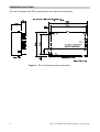
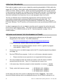
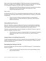
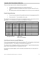
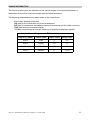
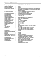
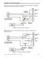
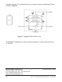
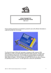
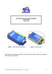
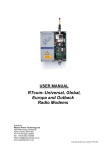
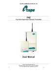
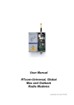
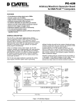
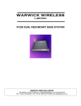
SR500 RECEIVER
OPERATING INSTRUCTIONS
1892 1211
These operating instructions are intended to provide the user with sufficient information to
install and operate the unit correctly.
The Wood & Douglas SR500 UHF synthesized receiver is intended to fulfil numerous OEM
applications by virtue of its highly flexible synthesized design approach, miniature size and
cost-effective performance. The unit complies with MPT1329 and as such does not require
an operating licence in the UK. It is also approved to various EC specifications.
1892 1211 - SR500 Receiver Operating Instructions - 2.10 / May 2006
1
DIMENSIONS AND FIXING
The unit is intended for PCB mounting within the customer’s equipment.
Figure 1 - SR unit dimensions and connectors
2
1892 1211 - SR500 Receiver Operating Instructions - 2.10 / May 2006
CONNECTION
Connection to the unit is via PL1, PL2 and PL3 which plug directly into the user's own
equipment. The location of these connectors is shown in Figure 1 and detailed in the
following tables.
PIN
NAME
1
0V
2
FUNCTION
0 volts
RF I/P RF input
3
0V
0 volts
REMARKS
common ground
50O input
common ground
Connector PL1 pin detail
PIN
NAME
1
+VIN
2
0V
FUNCTION
REMARKS
positive supply +6.0V to +14.0V
0 volts
common ground
Connector PL2 pin detail
PIN
NAME
FUNCTION
REMARKS
1
RSSI
S meter output 0.5 - 2V signal strength indicator, 60dB range
2
SQF
Squelch flag
open collector output, ON (low) = no signal (15V max)
250mV p-p +20% into 10kO
Note: The output audio is inverted with respect to the
ST500 (or similar Wood & Douglas product) audio
input.
3
AUDIO
AF output
4
DATA
Data output
open collector, no pull-up (14V max)
Note: The data output is inverted with respect to the
ST500 (or similar Wood & Douglas product) data
input.
5
+5V
+5 volt supply
output
50mA maximum permissible current drain
6
0V
0 volts
common ground
7
RS232 I/P serial
programming
input
8
RB1
9
RB2
10
RB3
parallel
frequency
select
RS232 programming input
Note: inverted TTL level data can also be used. If
not used, leave not connected, or connect to 0V
internal pull-up to +5V, active low
low < 0.8V
high > 4.0V
Connector PL3 pin detail
1892 1211 - SR500 Receiver Operating Instructions - 2.10 / May 2006
3
OPERATING FREQUENCIES
Each radio is made to order to cover a band (the switching bandwidth) of 5MHz within the
range 400 - 470 MHz. Each radio is also manufactured to work within a particular channel
width of 12.5kHz, 20kHz or 25kHz. Within the switching bandwidth, the unit can operate
on any frequency provided it is a multiple of the channel width, and up to 128 frequencies
can be stored as numbered channels. Before the unit leaves the factory, each of the 128
channels is allocated to a frequency, but you can reprogram them if you wish.
The first 16 channels can be individually programmed, and the remaining 112 are
sequentially programmed by entering a starting frequency and a step size. The
programming is done using Wood & Douglas software (STSRn00.exe) which runs on a
PC under Windows. The PC and the unit communicate via an asynchronous RS232 serial
link.
In order to reprogram the unit, an adaptor must be used to connect the unit to the serial
port of the PC and a power supply. This also inverts the readback output of the unit and
converts from TTL to RS232 levels for the PC. See the Appendix on page 13 for a
suitable adaptor.
OBTAINING AND RUNNING THE PROGRAMMING SOFTWARE
1.
Download the latest version of the programming software from the Wood &
Douglas site on the internet. The URL (address) is:
http://www.woodanddouglas.co.uk/products/software/stsrn00.exe
In case of difficulty, contact Sales at Wood & Douglas.
v
Note that you must have software version 1.00.21 or greater to program
units labelled “13MHz TCXO”
2.
Connect the unit to a suitable supply and to the PC using the programming adaptor
(see page 13).
3.
Run the STSRn00.exe program. It will run in a full-screen character session.
v
Please note that mouse operation is not supported with this program.
4.
You are prompted to enter the serial port number of the PC which is used to
communicate with the unit. Type 1 or 2 and press the <enter> key.
5.
In the same way, follow the prompt to select transmitter or receiver: 1: STn00
2: SRn00
6.
Finally, select the frequency range:
1 : ST/SR100 (125 - 180MHz)
2 : ST/SR500 (400 - 500MHz)
3 : ST/SR800 (860 - 880MHz)
At this stage, the main menu screen is displayed as shown in Figure 2. The screen
shows the default settings which are displayed whenever the STSRn00 software is run.
4
1892 1211 - SR500 Receiver Operating Instructions - 2.10 / May 2006
STSRn00 Programmer v.1.0.21
Chan
Chan
Chan
Chan
Chan
Chan
Chan
Chan
Chan
Chan
Chan
Chan
Chan
Chan
Chan
Chan
0
1
2
3
4
5
6
7
8
9
10
11
12
13
14
15
458.5
458.5125
458.525
458.5375
458.55
458.5625
458.575
458.5875
458.6
458.6125
458.625
458.6375
458.65
458.6625
458.675
458.6875
Start table 458.7
Max. Freq. 458.95
Table step 1 x 12.5
MHz <<
MHz
MHz
MHz
MHz
MHz
MHz
MHz
MHz
MHz
MHz
MHz
MHZ
MHz
MHz
MHz
MHz
MHz
kHz
Comparison freq.
12.5 kHz
Ref. (TCXO) freq. 12.8 MHz
Parallel channel select
COMMANDS:
F2 :copy Ch 16-31 to Ch 0-15
F3 :change comparison frequency
F4 :set parallel ch. mode
F5 :read from unit
F6 :program unit
F7 :program serial channel
F12:QUIT
Sequential frequencies, Chan. 16 to 127
Figure 2 - Programming screen
Note: Comparison and Ref (TCXO) frequencies are display-only, and cannot be
programmed by the user.
1892 1211 - SR500 Receiver Operating Instructions - 2.10 / May 2006
5
PROGRAMMING THE UNIT
Three steps are necessary:
v
v
v
Upload values from the unit
Edit the values
Download values to the unit
Uploading Current Unit Settings (F5)
First, you must read into the computer what is in the unit’s memory at present. To do this,
press F5. The data replaces the default on the screen.
v
The program insists that you do this before allowing you to reprogram the
unit to make it less likely that inappropriate values be entered.
v
However, once you have uploaded during a session, you may edit and
download the data to as many units as you wish.
Caution: If you do this, you must ensure that the units are all of the same
type. Check that all units are of the 13MHz TCXO type (“13MHz TCXO”
label affixed opposite serial number label) or the 12.8MHz TCXO type (no
such label). If you change unit type, you must use F5 again.
Programming Individual Channels (0-15)
To set the frequency of one of the first 16 channels (0-15), which can be individually set,
use the arrow keys to move the highlight over that channel and type in a frequency in
MHz.
v
The entered value must be an integer multiple of the Comparison Frequency
shown at the top right of the screen, otherwise an ‘invalid’ message is
displayed.
v
Make sure that the value is within the switching bandwidth of your unit, as
the software cannot prevent you from inserting an inappropriate value.
Press the <enter> key to complete.
Programming Sequential (Table or Block) Channels (16-127)
To set the frequency of channels 16-127, which can only be allocated as a block, use the
arrows to highlight Start Table and type in the lowest frequency (channel 16).
v
6
The entered value must be an integer multiple of the Comparison Frequency
shown at the top right of the screen, otherwise an ‘invalid’ message is
displayed.
1892 1211 - SR500 Receiver Operating Instructions - 2.10 / May 2006
Press <enter> then move the highlight to Table Step and type in the spacing between
channels in multiples of the Comparison Frequency shown at the top right. For example,
if the Comparison Frequency is 12.5kHz, enter 2 for a spacing of 25kHz.
v
Make sure that the Start and Maximum frequencies are within the switching
bandwidth of your unit, as the software cannot prevent you from
programming inappropriate values.
Press <enter>.
All channels from 16 to 127 are automatically programmed according to the Table (start)
Frequency and Table Step (channel spacing), and the Maximum Frequency is calculated
and displayed.
v
There is no way of viewing or editing the frequency of one particular
channel, although it can be calculated from Table Start, Table Step and
Maximum frequencies.
Setting a Maximum Frequency
When the Table Step is edited, the Maximum Frequency is recalculated and displayed.
However, you can override this such that any higher values are replaced with this value.
Thus all higher-numbered channels are programmed with this same frequency.
To do this, use the arrow keys to move the highlight over Maximum Frequency, type in a
maximum frequency, and press <enter>.
v
The entered value must be an integer multiple of the Comparison Frequency
shown at the top right of the screen, otherwise an ‘invalid’ message is
displayed.
Copying Values to the Individual Channels (F2)
To make programming easier, the first 16 channels of the sequential table (16-31) can be
copied in one step to the individual channels (0-15) by pressing the F2 button, and then
edited as described above.
Downloading New Settings to Unit (F6)
As yet, the settings have only been edited in the STSRn00 program. To download them
to the unit, press F6.
v
This is only permitted if F5 was previously used to upload settings at some
point during the session.
1892 1211 - SR500 Receiver Operating Instructions - 2.10 / May 2006
7
Channel Selection Mode (F7 and F4)
Having programmed frequencies into the channels, you can specify which channel to use
(channels 0-127) or that the channel will be selected by parallel logic levels (channels 0-7
only).
The unit defaults to serial channel selection whenever it has serial communications, which
includes whenever the STSRn00.exe software communicates with it.
To select serial control, and a channel from 0-127 (which will be used until further
commands are received), press F7. Type the new serial channel number and press
<enter>
v
The channel is displayed in ‘Serial channel selected’.
v
The channel command is sent to the unit immediately and becomes
operative.
To enable parallel channel selection mode press F4 (Parallel channel mode).
v
‘Parallel channel selected’ is displayed. The channel number is unknown,
because it depends on the logic levels applied to three inputs as described
on page 4.
Parallel channel mode select (F4) must be the last action before disconnecting the unit:
any further serial communication will reset it to serial mode.
Completing Programming
This completes programming and the unit may be disconnected. It is not necessary to
switch off power or stop the program first.
Programming Further Units
Further units may be programmed by disconnecting one unit and connecting the next,
which may be done without switching the power off.
v
If you want to use the channel frequency settings from the previous unit,
either as they are or as a basis for editing, do not stop the program, because
it does not save settings between sessions.
v
Note the caution on page 6 regarding mixed unit types
Proceed as above, using F6 to program the unit when all the channel parameters are
correct, and selecting a channel number (F7) or parallel selection (F4) before
disconnecting the unit.
8
1892 1211 - SR500 Receiver Operating Instructions - 2.10 / May 2006
CHANNEL SELECTION DURING OPERATION
There are three ways to select a channel during operation:
v
v
v
In hardware, using three logic lines to select channels 0-7
Using the STSRn00.exe software and a serial connection from a PC to the
unit
By sending a short serial data message to the unit from your own equipment.
Parallel Channel Selection
v
The unit must have been left in parallel mode when it was programmed (F4).
v
Only channels 0 - 7 are available in this mode
The channel in use depends on the logic levels supplied to pins 8 to 10, as set out in the
table below. If no connections are made, the unit defaults to channel 0.
CHANNEL SELECTION
PIN 10 (RB3)
PIN 9 (RB2)
PIN 8 (RB1)
CHANNEL
LOW
LOW
LOW
7
LOW
LOW
HIGH
6
LOW
HIGH
LOW
5
LOW
HIGH
HIGH
4
HIGH
LOW
LOW
3
HIGH
LOW
HIGH
2
HIGH
HIGH
LOW
1
HIGH
HIGH
HIGH
0
The logic levels are :
LOW < 0.8V
HIGH > 2V or floating
Serial Channel Selection (using STSRn00.exe)
If the unit was programmed for serial channel selection (F7), it will operate on the channel
nominated at that time. This setting is remembered during power off.
The channel can be changed by selecting a channel (press F7, type the channel number,
press <enter>) whenever the PC is connected to the unit.
By making up a special adaptor, the PC could be connected to the unit in situ while it is
operating.
1892 1211 - SR500 Receiver Operating Instructions - 2.10 / May 2006
9
Serial Channel Selection (own equipment)
If you want to select a channel using serial mode from your own equipment rather than
using the supplied software, then you must use this protocol:
1200 baud, RS232 levels, 1 start bit - 8 bit data - no parity - 1 stop bit
and send the following data sequence to the RS232 input, allowing at least 5ms between
the characters in the data stream:
x40 (decimal 64) synchronising code
Channel number in hex (decimal 0 to 127) (in bits 0-6, msb = 0)
x95 (decimal 149) confirmation byte
Any channel between 0 and 127 can be selected.
v
10
Any serial communication with the unit disables parallel selection.
1892 1211 - SR500 Receiver Operating Instructions - 2.10 / May 2006
RANGE INFORMATION
The following table gives an indication of the typical ranges to be expected between a
transmitter and receiver that have simple end-fed dipole antennas.
The following assumptions have been made in the calculations:
line-of-sight between antennas
0dB gain for the transmitter and receiver antennas
0dB loss for connectors and cables between the antenna and the radio connector
20dB fade and environmental margin
-100dBm received signal strength, allowing for digital and analogue signals
Range versus TX power
Frequency (MHz)
Power (mW)
Power (dBm)
Range (km)
458.5
1mW
0
0.5
458.5
10mW
10
1.7
458.5
100mW
20
5.3
458.5
500mW
27
11.9
1892 1211 - SR500 Receiver Operating Instructions - 2.10 / May 2006
11
TECHNICAL SPECIFICATION
Frequency range
Switching bandwidth
Frequency stability
Number of RF channels
:
:
:
:
RF channel selection
:
Channel switching delay
Channel spacing
Modulation type
Spurious emissions
(conducted & radiated)
Supply voltage
Supply current at 7.2V
Interface connections
RF connection
Operating temperature
Storage temperature
Weight
Size
Type approval
Sensitivity
:
:
:
:
:
:
:
:
:
:
:
:
:
:
Image/spurii
Intermodulation response
rejection
Blocking
Intermediate frequencies
Adjacent chan. selectivity
:
Audio response
Recovered audio level
Squelch type
General facilities
:
:
:
:
12
:
:
:
:
400 - 430 MHz, 430 - 470 MHz
5MHz
+2ppm
up to 128, frequencies programmable within switching
bandwidth (16 individually, 112 sequential table) using
supplied software
1 of 128 serial select (1200 baud RS232)
1 of 8 3-wire parallel select
<50ms across switching bandwidth
12.5kHz/20kHz/25kHz available
F1D/F2D/F3D
in accordance with R&TTE directive
6-14V DC, negative earth
<40mA
2 + 10 pin 0.1" header
3 pin 0.1" header
-20oC to +55oC
-30oC to +70oC
35g
60 x 39 x 15mm (2.36 x 1.53 x 0.59 inches)
MPT1329
<-115 dBm for 12dB SINAD (12.5 kHz)
<-117 dBm for 12dB SINAD (25 kHz)
(Measured with a flat audio response)
>60dB
>60dB
>75dB
45 MHz and 455kHz
>60dB for 12.5kHz channel spacing
>70dB for 25kHz channel spacing
9Hz to 6kHz at -3dB (25kHz channels)
>250mV p-p (+20%) into 10kO
Noise-operated open collector output
RSSI output (0.5 to +2V nominal)
+5V output
Independent data output
1892 1211 - SR500 Receiver Operating Instructions - 2.10 / May 2006
APPENDIX: TTL TO RS232 ADAPTOR
Many PCs do not require true RS232, and will work with the simple adaptor of Figure 3.
The transistor used must have a gain of at least 30.
Figure 3 - Simple programming adaptor
Figure 4 shows the circuit of an adaptor providing true RS232 for readback when
programming a unit.
Figure 4 - Programming adaptor (True RS232)
1892 1211 - SR500 Receiver Operating Instructions - 2.10 / May 2006
13
A suitable inverting TTL to RS232 buffer circuit using the industry-standard MAX232 part
is shown in Figure 5.
Figure 5 - Suggested RS232 buffer circuit
The MAX232 is obtainable from many component suppliers, e.g. RS Components stock
no. 655-290.
Wood & Douglas Ltd, Lattice House
Baughurst, Tadley, Hants, RG26 5LP
Tel:+44 (0)118 981 1444 Fax: +44 (0)118 981 1567
email: [email protected]
website: www.woodanddouglas.co.uk
14
, Wood & Douglas Ltd 2006
1892 1211 - SR500 Receiver Operating Instructions - 2.10 / May 2006