1
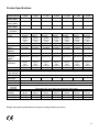
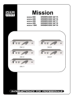
Palladium
P-400
P-500
P-700
P-900
P-1200
P-1600
P-2000
ORDERCODE D4131
ORDERCODE D4132
ORDERCODE D4133
ORDERCODE D4134
ORDERCODE D4135
ORDERCODE D4136
ORDERCODE D4137
Congratulations!
You have bought a great, innovative product from DAP Audio.
The Dap Audio Palladium Vintage Series brings excitement to any venue. Whether you want simple plug-&play action or a sophisticated show, this product provides the effect you need.
You can rely on DAP Audio, for more excellent audio products.
We design and manufacture professional sound equipment for the entertainment industry.
New products are being launched regularly. We work hard to keep you, our customer, satisfied.
For more information: [email protected]
You can get some of the best quality, best priced products on the market from DAP Audio.
So next time, turn to DAP Audio for more great sound equipment.
Always get the best -- with DAP Audio !
Thank you!
Dap Audio
Dap Audio Palladium Vintage Series ™ Product Guide
Warning..…...................................................................................………………………………………….
Safety-instructions………………………………………………………………………………………….….
Operating Determinations…………………………………………………………………………………….
2
2
3
Description..…..............................................................................……….…………………………………
Features Frontside………………………………………………………………………………….……...….
Backside…….……………………………………………………………………………………….……...….
4
4
5
Installation........................................................……..……………………………….………………………..
5
Set Up and Operation.....................................................................……..…………………………….……
5
Maintenance...................................................................................………..………….…….……………...
10
Troubleshooting............................................................................………………….………………….…..
10
Product Specifications.................................................................……………….…….…………………..
11
1
WARNING
CAUTION!
Keep this device away from rain and moisture!
FOR YOUR OWN SAFETY, PLEASE READ THIS USER MANUAL CAREFULLY
BEFORE YOUR INITIAL START-UP!
SAFETY INSTRUCTIONS
Every person involved with the installation, operation and maintenance of this device has to:
be qualified
follow the instructions of this manual
CAUTION! Be careful with your operations.
With a dangerous voltage you can suffer
a dangerous electric shock when touching the wires!
Before your initial start-up, please make sure that there is no damage caused by transportation. Should
there be any, consult your dealer and do not use the device.
To maintain perfect condition and to ensure a safe operation, it is absolutely necessary for the user to follow
the safety instructions and warning notes written in this manual.
Please consider that damages caused by manual modifications to the device are not subject to warranty.
This device contains no user-serviceable parts. Refer servicing to qualified technicians only.
IMPORTANT:
The manufacturer will not accept liability for any resulting damages caused by the non-observance of
this manual or any unauthorized modification to the device.
•
•
•
•
•
•
•
•
•
•
•
•
•
•
•
Never let the power-cord come into contact with other cables! Handle the power-cord and all
connections with the mains with particular caution!
Never remove warning or informative labels from the unit.
Do not open the device and do not modify the device.
Do not insert objects into air vents.
Do not connect this device to a dimmerpack.
Do not switch the device on and off in short intervals, as this would reduce the system’s life.
Only use device indoor, avoid contact with water or other liquids.
Avoid flames and do not put close to flammable liquids or gases.
Always disconnect power from the mains, when device is not used or before cleaning! Only handle
the power-cord by the plug. Never pull out the plug by tugging the power-cord.
Make sure that the available voltage is not higher than stated on the rear panel.
Make sure that the power-cord is never crimped or damaged. Check the device and the power-cord
from time to time.
Never use anything to cover the ground contact.
Make sure that there is sufficient room on all sides of the system for air circulation.
Avoid ground loops! Always be sure to connect the power amps and the mixing console to the same
electrical circuit to ensure the same phase!
Please turn off the power switch, when changing the power cord or signal cable.
2
•
•
•
•
•
•
•
•
•
•
•
•
•
•
•
•
•
•
Make sure that the amplifier is turned down, before turning the power on or off. So you can avoid
supersonic frequencies, which could damage your speakers.
Don't put your equipment next to TV, radio, etc., because of interference or distortion.
If you connect other parts of the system, be careful of ground loops.
The best way to avoid ground loops is connecting the electrical system ground to one central point
("star" system). In this case the mixer can act as a central point.
To prevent humming, please try different combinations of ground-lift or connect all chassis to the
system ground, either by a power cable or frontcover rack screws.
Before changing the ground, always turn off your amplifier.
Please read this manual carefully and keep it for future reference. Remember that the amplifier has a
better value on the market, if you save the carton and all packing materials.
Prevent distortion! Make sure that all components connected to the Palladium have sufficient power
ratings. Otherwise distortion will be generated because the components are operated at their limits.
Make sure you don’t use the wrong kind of cables or defective cables.
Make sure that signals into the mixer are balanced, otherwise hum could be created.
If device is dropped or struck, disconnect mains power supply immediately. Have a qualified
engineer inspect for safety before operating.
If the device has been exposed to drastic temperature fluctuation (e.g. after transportation), do not
switch it on immediately. The arising condensation water might damage your device. Leave the
device switched off until it has reached room temperature.
If your Dap Audio device fails to work properly, discontinue use immediately. Pack the unit securely
(preferably in the original packing material), and return it to your Dap Audio dealer for service.
Allow time to cool down, before cleaning or servicing.
For replacement use fuses of same type and rating only.
This device falls under protection class I. Therefore it is essential to connect the yellow/green
conductor to earth.
Repairs, servicing and electric connection must be carried out by a qualified technician.
WARRANTY: Till one year after date of purchase.
OPERATING DETERMINATIONS
This device is not designed for permanent operation. Consistent operation breaks will ensure that the device
will serve you for a long time without defects.
If this device is operated in any other way, than the one described in this manual, the product may suffer
damages and the warranty becomes void.
Any other operation may lead to dangers like short-circuit, burns, electric shock, lamp explosion, crash etc.
You endanger your own safety and the safety of others!
Improper installation can cause serious damage to people and property !
3
Description of the device
Features
The Palladium Vintage is an amplifier from DAP Audio.
There are 7 different versions: P-400, P-500, P-700, P-900, P-1200, P-1600, P-2000.
P400
Stereo mode:
• 2x 100 Watt RMS – 8 Ω
• 2x 200 Watt RMS – 4 Ω
Bridged mode: 400 Watt RMS – 8 Ω
P1200
Stereo mode:
• 2x 400 Watt RMS – 8 Ω
• 2x 600 Watt RMS – 4 Ω
Bridged mode: 1200 Watt RMS – 8 Ω
P500
Stereo mode:
• 2x 160 Watt RMS – 8 Ω
• 2x 250 Watt RMS – 4 Ω
Bridged mode: 500 Watt RMS – 8 Ω
P1600
Stereo mode:
• 2x 525 Watt RMS – 8 Ω
• 2x 800 Watt RMS – 4 Ω
Bridged mode: 1600 Watt RMS – 8 Ω
P700
Stereo mode:
• 2x 250 Watt RMS – 8 Ω
• 2x 350 Watt RMS – 4 Ω
Bridged mode: 700 Watt RMS – 8 Ω
P2000
Stereo mode:
• 2x 750 Watt RMS – 8 Ω
• 2x 1025 Watt RMS – 4 Ω
Bridged mode: 2050 Watt RMS – 8 Ω
P900
Stereo mode:
• 2x 300 Watt RMS – 8 Ω
• 2x 450 Watt RMS – 4 Ω
Bridged mode: 900 Watt RMS – 8 Ω
Overview
Frontside
1. Frontside Channel PROTECT.CLIP.POWER LEDS
2. Power-Switch / Circuit Breaker
3. Air intake grill
4. Channel Attenuators
4
Backside
5. Power cord
6. Fuse
7. 5-way Binding post output Connectors
8. Signal Ground Lift Barrier Strip
9. Bridged, Parallel, Stereo
10. Balanced Phone Jack Inputs
Installation
Palladium Vintage Installation
Remove all packing materials. Check that all foam and plastic padding has been removed.
Screw the equipment into a 19" rack. Connect all cables.
Always disconnect from electric mains power supply before cleaning or servicing.
Damages caused by non-observance are not subject to warranty.
Set Up and Operation
Before plugging the unit in, always make sure that the power supply matches the product specification
voltage. Do not attempt to operate a 120V specification product on 240V power, or vice versa.
Do not supply power before all components of the system are set up and connected properly.
Connection Input
The balanced phone jack inputs have a nominal impedance of 20 KΩ (10KΩ with unbalanced wiring) and
will accept the line level output of most devices. The correct input depends on 2 factors: (1) whether the
input signals are balanced or unbalanced, and (2) whether the signal source floats or has ground reference.
Figures provide examples of recommended connection techniques for each type of signal source. The
optional connector is shown.
The amplifier’s built-in 1/4“-Input-Phone-Connectors can be wired similarly for balanced or unbalanced,
floating or ground-referenced sources.
5
The phone connectors have a standard Tip-Ring-Sleeve (TRS) – configuration: The tip is positive (+), the
ring is negative (-) and the sleeve is ground.
a) Jack-Inputs Balanced Signals
Tip-HOT Ring-COLD Sleeve-Ground
b) Jack-Inputs Unbalanced Signals
Tip-HOT Sleeve Ground
c) XLR INPUTS Balanced Signals
Pin 1 Ground Pin2 HOT Pin3 COLD
Connecting Outputs
Speakers can be connected using Banana plugs, Speakon plugs or bare wire to the binding posts on the
rear panel of the amplifier. Consult the Wire-Gauge-Chart to determine suitable wire gauges for different
load impedances and cable lengths.
The red binding posts are considered „hot“, connected to the positive poles of the speakers, while the black
binding-posts are Signal Ground, connected to the negative poles of the speakers.
Never connect a „hot“ (red) Output to the Ground or to other „hot“ (red) Outputs! Always turn off the amplifier
before making connections.
Connecting Power
The actual current draw, the amplifier demands from the AC mains, depends on many factors (its load,
output level or the crest factor of its program material).
The power requirement is rated under typical music conditions, with both channels driven so those peaks
are just at the clipping point.
6
Stereo Operation
For stereo (dual channel) operation, set the mode select switch to the “Stereo” position. In this mode both
channels operate independently of each other, with their input attenuates controlling their respective levels.
A signal at Channel A’s input produces an amplified signal at Channel A’s output, while a signal at Channel
B’s input produces an amplified signal at Channel B’s output
Bridged Mono Operation
Both amplifier channels can be bridged together to make a very powerful single channel amplifier. When the
Mode switch is set to the “Bridge” position, 1 channel “pushes”, while the other “pulls” equally. Thus
effectively doubling the power. Use extreme caution when operating the amplifier in the bridged mode.
To bridge the amplifier, set the mode switch to the “Bridge” position. Apply the signal to Channel A’s input
and connect the speakers across the “hot” outputs – the red binding posts – of Channel A and B.
Channel B’s “hot” output is in phase with the input.
For operation adjust only the Channel A’s input attenuator, while Channel B’s input will not function
(Channel B’s input signal has been disconnected).
Never connect a „hot“-Output to ground or to other „hot“-Outputs!
Bridging Precautions
Never ground either side of the speaker cable when the amplifier is in bridged mode; Both sides are „hot“.
If an output patch panel is used, all terminals must be isolated from each other and from the ground.
7
Switches and controls
AC-Power-Switch-Circuit-Breaker
Never try to hold the switch in the „ON“-position, if it won’t stay there by itself.
The amplifier has a combined AC-switch/Circuit-Breaker on the front panel. If the switch shuts off during
normal use, push back to the ON position once. If it will not stay on, the amplifier needs servicing switches
and controls.
Input Attenuator
Whenever possible, set attenuates fully clockwise to maintain optimum system headroom. The input
attenuator controls (one for channel A, one for channel B) located at the front panel adjust gain for their,
respective amplifier channels in all modes. See the specifications at the end of this manual for standard
voltage gain and input sensitivity information. When operating the amplifier in bridged mode, both attenuates
must be in the same position, so the speaker load will be equally shared between the channels.
Mode-Select-Switch
The rear panel mode select switch determines whether the amplifier is in the stereo or bridged mono mode.
Do not operate the mode select switch with the amplifier on.
Signal Ground Lift Jumper
In a properly designed system (for safety and to minimize noise), the amplifier should receive its ground
from the line cord. Whenever possible, the signal source equipment should share the same AC ground as
the amplifier(s). In some cases, however, this may result in a ground loop. If this happens, remove the
ground lift jumper (supplied) on the rear barrier strip. This jumper electrically connects the signal ground to
the chassis / AC ground. If the jumper is removed, the signal ground is lifted and completely isolated from
the chassis / AC ground. Do not remove the jumper if the amplifier and the signal source equipment are not
on the same AC ground
Indicators
The Palladium features 4 front LED indicators per channel: Clip, Signal, Protect und Power. These LED
indicators inform the user of each channel’s operating status and warn of possible abnormal conditions.
Clip LED
A channel’s red clip LED will light dimly at the onset of clipping and increase in brilliance, as clipping
becomes more severe, staying on until the clipping ceases. If the LED’s are flashing quickly and
intermittently, the channel is just at the clip threshold, while a steady, bright glow means the amp is clip
limiting, or reducing gain to prevent severely clipped waveforms reaching the speakers.
Signal-LED
This green LED lights, when its channel produces an output signal of about 4 Volt RMS or more (0,1V or
more at the input, with 0dB attenuation and standard 40X voltage gain). It is useful to determine whether the
amplifier is amplifying a signal.
Protect LED
When the red LED lights, indicating that the channel has overheated, the channel’s output relay is open, and
the speaker(s) has been disconnected for any of the following reasons:
1. The unit was just powered up and is in the turn – on delay mode
2. The amplifier senses a DC voltage at its output.
Power LED
This indicator LED lights, when the amplifier has been turned on, AC power is available and the low-voltage
power supply and fan are operational.
8
Input Attenuates
The two input attenuator controls, located at the front panel, adjust gain for their respective amplifier
channels in stereo mode. With attenuate fully clockwise at 0 dB, professional power amplifiers have the
rated power (when the rated input is 0,775V) In bridged mode, only channel A’s attenuate controls the
power level, while channel B’s does not function.
Protection Features
Every amplifier incorporates several circuits to protect themselves and the speakers under virtually any
situation. Dap Audio has attempted to make the amplifier as “foolproof” as possible by making it impervious
to short and open circuits, DC Voltage and overheating.
When a problem occurs, that causes a channel to go into a protection mode, the PROTECT for that channel
will glow. DC voltage on the output, excessive subsonic frequencies, or thermal overloads will cause the
channel’s output relay to disconnect the speaker load, until the problem is corrected or the amplifier cools
down.
The internal fan(s) will keep the amplifier operating well within its intended temperature range under all
normal conditions.
When a channel’s heat sink temperature reaches 90 ºC, which may indicate an obstructed air supply,
clogged air filter, etc, the channel will disconnect its load. Normal operation will resume automatically once it
cools to 80 ºC. During this time, the channel’s PROTECT LED will light.
Short Circuit
If an output is shorted, the protection circuit will be more sensitive, than in the normal protection situation
and will protect the channel’s output transistors from the current stress. The channel’s PROTECT LED will
light. If the short circuit remains, the channel will eventually thermally protect itself by disconnecting the load.
DC Voltage Protection
If an amplifier channel detects DC voltage at its output, its output will immediately open to prevent speaker
damage. The channel’s PROTECT LED will light.
Subsonic Frequencies
All amplifiers have a built-in subsonic frequency protection circuit, cornered at 10Hz, for each channel.
An additional feature is a special high frequency protection technology, which enables you to automatically
disconnect speakers, when excessive high frequency energy appears at the output.
Turn-On/Turn-Off-Protection
At power up, the speakers are disconnected. The power supplies charge for about 2-3 seconds and
stabilize, and then the speakers are connected. When power is removed, speaker loop is synchronized with
the turn off signal, therefore no thumps or pops are heard.
Speaker-Protection
All amplifiers automatically protect speakers from DC voltage, subsonic signals and excessive high
frequency signal, but users should be aware of the application limits of their speakers.
Be aware that the amplifiers power does not exceed the speaker’s power capabilities.
9
Maintenance
The Dap Audio Palladium Vintage Series requires almost no maintenance. However, you should keep the
unit clean. Disconnect the mains power supply, and then wipe the cover with a damp cloth. Do not immerse
in liquid. Do not use alcohol or solvents.
Keep connections clean. Disconnect electric power, and then wipe the audio connections with a damp cloth.
Make sure connections are thoroughly dry before linking equipment or supplying electric power.
Troubleshooting
DAP Audio Palladium Vintage Series
This troubleshooting guide is meant to help solve simple problems.
If a problem occurs, carry out the steps below in sequence until a solution is found. Once the unit operates
properly, do not carry out following steps.
1. If you experience low output or no output at all, unplug the amplifier immediately.
2. Check power from the wall, all cables, the fuse, etc.
3. If all of the above appears to be O.K., plug the unit in again.
4. If nothing happens after 30 seconds, turn off the amplifier and unplug the device.
5. Return the machine to your DAP Audio dealer.
10
Product Specifications
Specification
8 Ω Stereo
Power (RMS)
4 Ω Stereo
Power (RMS)
8 Ω Bridge
Power (RMS)
Frequency
Response
THD into 4Ω,
1 KHz
SMPER IMD
Slew Rate
Damping
Factor
Input CMRR
(@1Khz)
Voltage Gain
Input
Sensitivity
(@8Ω)
Input
Impedance
Hum and Noise
Crosstalk
Connectors
(per channel)
Power Supply
Max. Current
Draw 220V
Cooling
Controls
Indicators (per
channel)
Protection
Dimensions
(LxWxH)
Gross Weight
Net Weight
P-400
P-500
P-700
P-900
P-1200
P-1600
P-2000
100W
160W
250W
300W
400W
525W
750W
200W
250W
350W
450W
600W
800W
1025W
400W
500W
700W
900W
1200W
1600W
2000W
20 Hz -20KHz: + 0.1 / - 3 dB (1W / 8 Ω)
<0.05%
@200W
<0.05%
@250W
<0.05%
@350W
<0.05%
@450W
<0.05%
@600W
<0.05%
@800W
<0.05%
@1025W
<0.01%
@100W
into(60Hz &
7 Khz)
<0.01%
@160W
into(60Hz &
7 Khz)
<0.01%
@250W
into(60Hz &
7 Khz)
<0.01%
@300W
into(60Hz &
7 Khz)
<0.01%
@400W
into(60Hz &
7 Khz)
<0.01%
@525W
into(60Hz &
7 Khz)
<0.01%
@750W
into(60Hz &
7 Khz)
40V/ µs
300:1,1
KHz@8Ω
>60dB
40V/ µs
300:1,1
KHz@8Ω
>60dB
40V/ µs
300:1,1
KHz@8Ω
>60dB
40V/ µs
300:1,1
KHz@8Ω
>60dB
40V/ µs
350:1,1
KHz@8Ω
>60dB
50V/ µs
400:1,1
KHz@8Ω
>60dB
60V/ µs
500:1,1
KHz@8Ω
>60dB
50x standard
50x standard
50x standard
61x standard
70x standard
80x standard
91x standard
0.775V for
rated power
0.775V for
rated power
0.775V for
rated power
0.775V for
rated power
0.775V for
rated power
0.775V for
rated power
0.775V for
rated power
20KΩ,
balanced
10KΩ,
unbalanced
20KΩ,
balanced
10KΩ,
unbalanced
20KΩ,
balanced
10KΩ,
unbalanced
20KΩ,
balanced
10KΩ,
unbalanced
20KΩ,
balanced
10KΩ,
unbalanced
20KΩ,
balanced
10KΩ,
unbalanced
20KΩ,
balanced
10KΩ,
unbalanced
-103dB
<60dB
5A
-103dB
-103dB
-103dB
-103dB
-103dB
<60dB
<60dB
<60dB
<60dB
<60dB
Female XLR (pin 2+), TRS (tip +), 5 – way Output binding post
6A
7A
230 V / 50 – 60 Hz
8A
8A
12 A
-103dB
<60dB
15 A
2 variable speed DC fans
2 front attenuators, rear panel signal ground lift jumper
PROTECT LED, CLIP LED, SIGNAL LED, POWER LED
483x400x
89 mm
20 Kg
18 Kg
Temperature, DC, sub / ultea, sonic short cicuit, IGM, output
483x400x
483x400x
483x400x
483x400x
483x400x
89 mm
89 mm
89 mm
89 mm
89 mm
22 Kg
24 Kg
26 Kg
28 Kg
30 Kg
20 Kg
22 Kg
24 Kg
26 Kg
28 Kg
483x400x
89 mm
32 Kg
30 Kg
Design and product specifications are subject to change without prior notice.
11
2003 Dap Audio.