1
User's Manual
VERB
24 32 BIT DIGITAL EFFECTS
R
LTO
www.altoproaudio.com
Version 2.2 August 2004
English
the recommended fuse type as indicated in this manual.
Do not short-circuit the fuse holder. Before replacing the
fuse, make sure that the product is OFF and disconnected
from the AC outlet.
SAFETY RELATED SYMBOLS
CAUTION
RISK OF ELECTRIC SHOCK
DO NOT OPEN
Protective Ground
This symbol, wherever used, alerts you to the presence of un-insulated and dangerous voltages within the product enclosure. These are voltages that
may be sufficient to constitute the risk of electric
shock or death.
This symbol, wherever used, alerts you to important operating and maintenance instructions.
Please read.
Protective Ground Terminal
Operating Conditions
Always install in accordance with the manufacturer's
instructions.
To avoid the risk of electric shock and damage, do not
subject this product to any liquid/rain or moisture. Do
not use this product when in close proximity to water.
AC mains (Alternating Current)
Hazardous Live Terminal
ON:
Before turning the product ON, make sure that it is
connected to Ground. This is to prevent the risk of
electric shock.
Never cut internal or external Ground wires. Likewise,
never remove Ground wiring from the Protective Ground
Terminal.
Denotes the product is turned on.
Do not install this product near any direct heat source.
OFF: Denotes the product is turned off.
WARNING
Describes precautions that should be observed to
prevent the possibility of death or injury to the user.
Do not block areas of ventilation. Failure to do so could
result in fire.
Keep product away from naked flames.
IMPORTANT SAFETY INSTRUCTIONS
CAUTION
Describes precautions that should be observed to
prevent damage to the product.
Read these instructions
Follow all instructions
Keep these instructions. Do not discard.
Heed all warnings.
WARNING
Power Supply
Ensure that the mains source voltage (AC outlet) matches
the voltage rating of the product. Failure to do so could
Only use attachments/accessories specified by the
manufacturer.
Power Cord and Plug
result in damage to the product and possibly the user.
Unplug the product before electrical storms occur and
when unused for long periods of time to reduce the risk of
Do not tamper with the power cord or plug. These are
designed for your safety.
electric shock or fire.
If the plug does not fit your AC outlet seek advice from a
qualified electrician.
External Connection
Always use proper ready-made insulated mains
cabling (power cord). Failure to do so could result
in shock/death or fire. If in doubt, seek advice from
a registered electrician.
Do Not Remove Any Covers
Within the product are areas where high voltages may
present. To reduce the risk of electric shock do not remove
any covers unless the AC mains power cord is removed.
Covers should be removed by qualified service
personnel only.
No user serviceable parts inside.
Fuse
To prevent fire and damage to the product, use only
1
Do not remove Ground connections!
Protect the power cord and plug from any physical
stress to avoid risk of electric shock.
Do not place heavy objects on the power cord. This
could cause electric shock or fire.
Cleaning
When required, either blow off dust from the product or
use a dry cloth.
Do not use any solvents such as Benzol or Alcohol.
For safety, keep product clean and free from dust.
Servicing
Refer all servicing to qualified service personnel only. Do
not perform any servicing other than those instructions
contained within the User's Manual.
PREFACE
Dear Customer:
Thanks for choosing
researches.
LTO
VERB and thanks for choosing the one of results of the
LTO AUDIO TEAM job and
For our LTO AUDIO TEAM, music and sound are more than a job...are first of all passion and let us say...our
obsession!
We have been designing professional audio products for a long time in cooperation with some of the major brands in
the world in the audio field.
The LTO line presents unparalleled analogue and digital products made by Musicians for Musicians in our R&D Centers
in Italy, Netherlands, United Kingdom and Taiwan. The core of our digital audio products is a sophisticated DSP (Digital
sound processor) and a large range of state of the art algorithms which have been developed by our Software team for
the last 7 years.
Because we are convinced you are the most important member of LTO AUDIO TEAM and the one confirming the quality
of our job, we'd like to share with you our work and our dreams, paying attention to your suggestions and your comments.
Following this idea we create our products and we will create the new ones! From our side, we guarantee you and
we will guarantee you also in future the best quality, the best fruits of our continuous researches and the best prices.
Our LTO VERB is the result of many hours of listening and tests involving common people, area experts,
musicians and technicians.
The result of this effort is the realization of effects such as reverb, chorus, flanger and delay that are today the best
guitar amplifiers and studio equipment in the world, effects that we collected in our single rack unit, efficient and easy
to use LTO VERB.
Nothing else to add, but that we would like to thank all the people that made the LTO VERB a reality, available
to our customers ,and thank our designers and all the LTO staff, there to make possible the realization of products
containing our idea of music and sound and there to support you, our customers, in the best way, conscious that
you are our best richness.
Thank you very much.
LTO AUDIO TEAM
2
TABLE OF CONTENTS
1. INTRODUCTION ................................................................................................................................................................... 4
2. FEATURE LIST ..................................................................................................................................................................... 4
3. FRONT AND BACK PANELS DESCRIPTION .......................................................................................................... 4
3.1 Control Panel (Front Panel)
a. Program and Variation Selections
b. Analog Levels
c. LED and Illuminated Power Switch
3.2 Analog Connections (Back Panel)
a. Analog Inputs/Outputs
b. MIDI Connectors
c. Power Connector
4. INSTALLATION & CONNECTION ................................................................................................................................. 5
4.1 Audio Connections and Power Up
a. Audio Connections
b. Power Up Setting
4.2 Analog
a. Levels Setting
4.3 Installation
a. Mono Use of VERB
b. Standard Use
c. Application Examples
- Line Instrument
- Mixer
4.4 Operational Overview
5. ALGORITHMS DESCRIPTIONS ....................................................................................................................................10
5.1 Reverbs
a. Halls
b. Rooms
c. Plates
5.2 Modulations
a. Tremolo
b. Chorus
c. Flange
d. Rotary (Speakers)
5.3 Delay
5.4 Effects Functional Data
5.5 Factory Presets Program Chart
6. TECHNICAL SPECIFICATIONS ...................................................................................................................... 32
7. WARRANTY ....................................................................................................................................................... 33
3
1. INTRODUCTION
Purchasing LTO VERB, you purchased a very powerful effect processor, easy to use and contained in a very
efficient rack package.
LTO VERB is divided in 9 effects algorithms and for each of them there are several factory presets so to reach
totally 64 factory presets that can be used as starting point to create 64 customer's presets storable into 64 available
memory locations. The powerful Editing section of the VERB allows the users to modify the presets accessing a huge
number of parameters defining the algorithms.
All the algorithms are based on classical algorithms for the effects generation and environment response modelling,
modified and optimized, thank the experience of LTO AUDIO TEAM researchers.
2. FEATURE LIST
Robust and Compact Design
24/32 bits Digital Audio Processor
MPU Control
Variable Input Output Gain
Illuminated Power Switch
Digital Saturation LED
Easy to Operate Front Panel Controls and Display
SMT Design for Greater Reliability
Optimized Signal Path to Provide Superior Sound
Manufactured Under QS9000, VDA6.1 Quality System
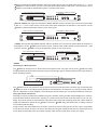
3. FRONT AND BACK PANELS DESCRIPTION
3.1 Control Panel (Front Panel)
(8)
(1)
(2)
UP
PROCESS
OVERFLOW
SAVING
PRESET
(3)
(4)
(5)
CLIP
VERB
-6
-12
R
LTO
-18
ON
-24
OFF
-30
DOWN
(6)
(7)
ENTER
ESC
EDIT
UTIL
DIGITAL MIX
ON / OFF
(9) (10) (11) (12) (13) (14)
a. Program and Variation Selections
(1) Digital Overflow LED
(2) Saving Preset LED
(3) Edit LED
(4) Utility LED
(5) Digital Mix ON / OFF LED
(6) VU-Meter
(7) LCD Display 20 2 alphanumeric
(8) Up key
(9) Down key
(10) Enter key
(11) Esc key
(12) Edit key
(13) Utility key
(14) Digital Mix ON / OFF key
(15) Analog Input volume
(16) Dry/Wet Mix Potentiometer for Analog Dry/Wet Mixing
(17) Analog Output gain
(18) Power ON/OFF Switch
4
10
INPUT LEVEL
DRY
WET
MIX
OFF
10
OFF
OUTPUT LEVEL
POWER
(15)
(16) (17)
(18)
24 32 BIT
DIGITAL EFFECTS
b. Analog levels
- Analog Input Level Potentiometer (15): The input level control sets the main input gain, before the signal reaches
the input bus. It controls both the Input1 and Input2 levels simultaneously.
- Dry/Wet Mix Potentiometer for Analog Dry/Wet Mixing (16): This potentiometer represents one of the most
powerful features of VERB. VERB offers the possibility to mix Dry and Wet signals digitally or analogically.
When Digital Mix ON/OFF key is pressed and the related Digital Mix ON/OFF LED is on (red), VERB is allowing
the Dry/Wet digital mixing with the chosen percentages operated by "%dir" and "%eff" functions available within
"EDIT MENU". When Digital Mix ON/OFF is on, the analog mix potentiometer must be positioned on fully Wet,
When Digital Mix ON/OFF is off (Digital Mix ON/OFF LED is turned off), the Dry/Wet Mix Potentiometer for Analog
Dry/Wet Mixing (16) can be used to analogically adjust the balance between the Dry signal coming into the input
and the Wet one coming from VERB after the effect's digital process.
- Analog Output Level Potentiometer (17): The output level control set the level going to the amplifier or mixer
from this apparatus.
c. LED and Illuminated Power Switch
- Digital Saturation LED (1): Displays the signal level coming into the input during normal operation, if the signal
level is too high, this LED will turn red and you will begin to hear the signal distortion.
- Power On/Off Switch (18): Turns the apparatus on and off.
3.2 Analog Connections (Rear Panel)
AC INPUT
95-120V /210-240V 60-50Hz
Rated Power Consumption 9W
PUSH
MODEL
TIP/PIN 2
RING/PIN 3
SLEEVE/PIN 1
FUSE:
A102
210-240V: T250mAL 250VAC
95-120V: 500mA 250VAC
REPLACE FUSE WITH CORRECT
TYPE ONLY
SERIAL
Apparaten skall anslutas till
jordat uttag nar den ansluts
till ett natverk
CODE
TIP/PIN 2
RING/PIN 3
SLEEVE/PIN 1
ON
OFF
OUTPUT
THRU
INPUT
OUTPUT2
OUTPUT1
MONO
PUSH
TIP/PIN 2
RING/PIN 3
SLEEVE/PIN 1
NEW
TIDE
NEW
3
2
TIDE
3
1
INPUT2(MONO)
2
1
INPUT1
MIDI
a. Analog Inputs/Outputs
- INPUTS: These are 1/4" TRS and XLR balanced connectors which connect to sources such as the effects
sends of mixing console. They may be used with nominal input levels from consumer to professional audio. For
mono application, use the INPUT2, once set manually the MONO ON/OFF switch to ON.
- OUTPUTS: These are 1/4" TRS and XLR balanced connectors which connect to devices such as the effects
returns on a mixing console or power amplifier inputs. For Mono applications, use the OUTPUT1 or the
OUPUT2 and the OUTPUT2 once set manually the MONO ON/OFF switch to ON.
- MONO ON/ OFF switch: this switch sets the operational mode, switch to ON for mono application.
b. MIDI Connectors
- MIDI IN: DIN connector for the MIDI input to the VERB.
- MIDI THRU: DIN connector for the MIDI thru.
- MIDI OUT: DIN connector for the MIDI output from the VERB.
c. Power Connector
- POWER CONNECTOR: This is the plug for connecting the power supply to the
VERB.
4. INSTALLATION & CONNECTION
4.1 Audio Connections and Power Up
a. Audio Connections
The connections between the VERB and the other audio devices have to be made using high quality cables
so to prevent bad performances of the VERB itself. So it should be good to use low-capacitance shielded
cables with a flexible internal conductor. Connect the cables to the VERB properly by observing the following
precautions:
Do not bundle audio cables with AC power cords.
Avoid place audio cables and VERB, near sources of electromagnetic interference such as transformers,
monitors, computers, etc.
Always unplug cables by firmly grasping the body of the plug and pulling directly outward.
Do not place cables where they can be stepped on.
Avoid twisting a cable or having it make sharp, right angle turns.
5
b. Power Up Setting
After making your connections, turn on the system power using this procedure:
Before turning on the VERB power, check if:
All connections been have made correctly.
The volume controls of the amplifier or mixer are turned down.
Insert the Power plug into the POWER input on the rear panel of the VERB and plug the power cord into an
AC outlet.
Turn on the power of the VERB, pushing the ON/OFF button on the front panel.
Turn on the power of the amplifier/mixer, and adjust the volume.
4.2 Analog
a. Levels Setting
Proper setting of the input and output levels is crucial in order to achieve the maximum signal-to-noise ratio. It
is possible to say that it is usually best to set both input and output level controls at 3/4 or 75% of full. This will
decrease the possibility of overload distortion and keep the amount of background noise to a minimum.
If the VU-Meters or the Digital Saturation LED on the VERB begin to clip (turn red), turn down the Input level
or decrease the volume of the source (instrument, mixer send, etc.). If the output level is causing the mixer or
amp to distort, turn the Output Level down.
4.3 Installation
a. Mono Use of VERB
The VERB's INPUT 2 can be used as MONO input when necessary setting in the proper way the switch
MONO ON/OFF on the back panel of VERB itself.
When the MONO ON/OFF switch is manually set to ON position, physically the INPUT 2 will be routed also
on the internal INPUT 1 line.
Inputs
Outputs
INPUT 2
OUTPUT 1
OUTPUT 2
ON position
INPUT 1
INPUT 2
OUTPUT 1
OUTPUT 2
OFF position
When the MONO ON/OFF switch is set to OFF position, the INPUT 2 is no more routed on the INPUT 1 line
and VERB works in fully stereo configuration and MUST have stereo input signals for a proper functioning of
the process algorithm.
When the input signal is mono, it has to be connected to the INPUT 2 and the MONO ON/OFF switch MUST be
set to ON.
b. Standard Use
The VERB may be placed almost anywhere: on a table, on top of an amp, next to a mixing console. If it will
be on furniture, check the rubber feet provided to the bottom of the unit. Make sure to place the VERB away
from other audio equipment that may induce fields, and away from the signal wiring. It is possible that VERB
may pick up noise fields generated by other equipment such as large power amplifiers; in this case, move the
VERB until the noise goes away.
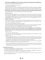
c. Application Examples
- LINE INSTRUMENT
When connecting audio cables and/or turning power on and off, make sure that all devices in your system have
their volume controls turned down.
VERB has four inputs (two 1/4" TRS inputs and two XLR balanced inputs) and four outputs (two 1/4" TRS
outputs and two XLR balanced outputs) allowing the VERB to be used in a classical Stereo in and Stereo Out
connection or in Mono configuration as described above.
6
MONO. Set manually the MONO ON/OFF switch to position ON. Connect one audio cable to the INPUT 2 of the
VERB from a mono source, and one or two other audio cables from the OUTPUT 1 and OUTPUT 2 of the
VERB to a mono/stereo amplification system or one/two mixer inputs.
From Instrument or Effects Send
To Amplifier or Mixing Console
OUTPUT 1
INPUT 2
CLIP
VERB
-6
-12
R
LTO
-18
UP
PROCESS
OVERFLOW
SAVING
PRESET
DOWN
ENTER
ESC
ON
-24
OFF
-30
EDIT
UTIL
DIGITAL MIX
ON / OFF
10
DRY
INPUT LEVEL
WET
MIX
OFF
10
24 32 BIT
DIGITAL EFFECTS
OFF
OUTPUT LEVEL
POWER
MONO IN, STEREO OUT. Again set manually the MONO ON/OFF switch to position ON. Connect one audio cable
to the INPUT 2 from a mono source, and now two other audio cables from the OUTPUT 1 and OUTPUT 2 of the
VERB to a stereo amplification system or two mixer inputs.
From Instrument or Effects Send
To Amplifier or Mixing Console
INPUT 2
OUTPUT 1
OUTPUT 2
CLIP
VERB
-6
-12
PROCESS
OVERFLOW
UP
R
LTO
-18
SAVING
PRESET
ON
-24
OFF
-30
DOWN
ENTER
ESC
EDIT
UTIL
DIGITAL MIX
ON / OFF
10
DRY
INPUT LEVEL
WET
MIX
OFF
10
24 32 BIT
DIGITAL EFFECTS
OFF
OUTPUT LEVEL
POWER
STEREO. Set manually the MONO ON/OFF switch to position OFF. Connect two audio cables to the INPUT 1
and INPUT 2 of the VERB from a stereo source, and two other audio cables from the OUTPUT 1 and
OUTPUT 2 of the VERB to a stereo amplification system or two mixer inputs.
To Amplifier or Mixing Console
From Instrument or Effects Send
INPUT 1
OUTPUT 1
INPUT 2
OUTPUT 2
CLIP
VERB
-6
-12
R
LTO
-18
UP
PROCESS
OVERFLOW
SAVING
PRESET
DOWN
ENTER
ESC
ON
-24
OFF
-30
EDIT
UTIL
DIGITAL MIX
ON / OFF
10
DRY
INPUT LEVEL
WET
MIX
OFF
10
24 32 BIT
DIGITAL EFFECTS
OFF
OUTPUT LEVEL
POWER
- MIXER
Interfacing to a Mixing Console
The VERB can accept mono or stereo sends at all system levels. The input circuitry of the VERB can easily
accept professional levels while having enough input and output gain to interface with the low signal levels of
home recording systems.
Aux
Send
Aux
Return
MIXING CONSOLE
CLIP
VERB
-6
-12
R
LTO
-18
UP
PROCESS
OVERFLOW
SAVING
PRESET
DOWN
ENTER
ESC
ON
-24
OFF
-30
EDIT
UTIL
DIGITAL MIX
ON / OFF
10
INPUT LEVEL
DRY
WET
MIX
OFF
10
24 32 BIT
DIGITAL EFFECTS
OFF
OUTPUT LEVEL
POWER
The VERB may be connected to a mixing console using Aux sends and returns. Another way of interfacing the
VERB to a mixer or recording console would be in-line between the output of your mixing console and the
input of a tape deck or power amplifier. This last setup would be used only if you wanted to effect the entire mix.
Using Aux Sends and Returns
Generally, on mixing consoles are available two types of auxiliary sends: pre-fader sends (headphone or monitor),
and post-fader sends for effects units. Typically, if a mixer has more than two sends per channel (4, 6 or 8, perhaps), the first two sends are reserved for the pre-fader sends, while the remaining sends are used to send the
signal to be effected to devices as the VERB. Connect the VERB using post-fader sends, so fading a channel
out, its effects will fade also.
Using a mixer's aux sends allows each channel to have its own level control going to the aux output. It is possible
to mix all the channels we want to be sent to the effects by using the individual channels' aux send levels on the
mixer. Most consoles also have aux master controls, which set the overall level of each aux output.
7
Sending signal to the VERB is only half of the process. With a mixing console, the output of the VERB must
go back to the mixer and turned up in the mix before to be able to hear it. Depending from the mixer, there are
two options for returning the effected signal to the mix:
connecting to dedicated aux return inputs, or
connecting to channel inputs.
Everything is easy if the mixer provides dedicated inputs (called returns) for effect devices like the VERB.
If the mixer does not have these, or the available returns have already been used all, it possible to connect
the VERB to channel inputs (if there are any remaining). The effect returns generally should only contain
effected signal, and not have any unaffected or "DRY" signal mixed with it (since these two signals are blended
together at the mixer). Therefore, it is necessary to set the mix so that only effected ("WET") signal is present
at the VERB's outputs. To do this, turn the Mix control all the way to the right.
MONO IN - STEREO OUT.
If you only want to use the VERB for a mono input signal and to connect both of its outputs back to the mixer,
you will need three audio cables. Connect an audio cable from an effect send to the INPUT 2 of the VERB
once set the MONO ON/OFF switch to ON and another 2 audio cable from the OUTPUT 1 and OUTPUT 2 outputs
of the VERB to a couple of effect return or other mixer inputs. On the reverb effect VERB creates a stereo
output, even though only a single input is used.
STEREO IN - STEREO OUT.
This connection is similar to the one described above. However, by utilizing two sends from the mixer, we have
to use one more audio cable to send a stereo signal to the VERB's inputs. The use of a stereo input is especially useful on the true stereo reverb program.
HOW TO SET AUX SEND AND RETURN LEVELS ON THE MIXER.
In the above connections, it is necessary to set proper levels on the mixer's individual Aux Sends, Aux Masters,
and Aux Return masters (as well as the VERB's own controls) to get good, clean, quiet results.
Improper level setting is the most common cause of noise and distortion problems.
By having the correct level at every point in the send/return chain, it is possible to avoid overloading distortion
and minimize noise. The most common mistake using effect units like the VERB is to have too low the input
signal level and to increase too much the output level to compensate the input and reach the desired effects
level: this amplifies the noise, reducing headroom. Here is a procedure that will give good results with most
standard equipment:
1. Set the mixer's input levels correctly.
2. Turn up the mixer channels' AUX SEND and AUX MASTERS (if applicable) to a nominal level (this is usually
between "noon" and "3:00" on a rotary knob).
3. Play the source.
4. Turn up the VERB's INPUT level until you see the Digital Saturation LED start lighting on peaks; then reduce
it slightly until the LED stops lighting. The ideal input level, to minimize the noise, is just below the Clipping
level. But if other instruments will be added to the mix later, or levels are unpredictable (as in a live Show),
it's preferable to leave additional headroom by turning the input level down a bit more.
5. Depending on the input sensitivity of the mixer's channels or Aux Returns, the OUTPUT knob of the
should be set somewhere between "2:00" and fully clockwise ("5:00").
VERB
6. Turn up the AUX RETURN level until the desired level of effect in the mix is reached. The control in the chain
that may need to be set to a low level is the Aux Return on the mixer itself. Here is where should be increased
or decreased the overall effect level in the mix to minimize the noise.
4.4 Operational Overview
Switching ON the VERB, after an initialization procedure, the last stored preset will be loaded and will be lost
all the NOT stored modifications to the last preset itself.
To load exactly the last preset's configuration running before the switching OFF of the
store these modifications using the STORE Function available in UTILITY Menu.
VERB, it's necessary to
After the initialization procedure, on the LCD will appear the first field of the UTILITY Menu and the LED related
to the UTILITY Button will turn ON.
8
Utility Button(13): To access the UTILITY Menu it's necessary to push the UTILITY Button (13).
If the VERB is already working on Utility Menu (Utility LED (4) = ON) each further use of the button will have
no effect.
Using the Utility Menu is possible to access the following functions:
Load Preset: this function allows the loading of one of the 128 available presets, where the first 64 presets
(1, 64), are factory presets, and the presets from 65 to 128 are the User's configurable presets and all not initialized (Empty) at VERB selling time.
To Load a preset:
Select "Load Preset" using UP/DOWN buttons
Press ENTER button to access the further sub menu
Select the chosen preset using UP/DOWN buttons
Press ENTER to load the preset or press ESC button if you decide to not load anymore the preset
Once terminated the sequence above, on the display will appear the name of the selected preset and the system
will go back to the starting menu.
Store Preset: this function allows the storing on one of the 64 available memory locations the modified (using
the Editing Menu) user's preset, starting from one of the 64 available factory presets.
To Store a preset:
Select "Store Preset" using UP/DOWN buttons
Press ENTER button to access the further sub menu
Select the memory location (Empty or already occupied from a previous user's preset) where to store the new
user's preset using UP/DOWN buttons
If you want to give up, press ESC to go back to the main menu without storing the new preset otherwise press
ENTER to store the new preset. The user can choose the identification name for the new preset using 6
characters max.
The blinking character show the character will be modified using the UP/DOWN buttons. When the right character
appears, press enter to confirm the character itself and pass to the next one. Pressing ESC before the 6t hcharacter,
the old name will be maintained as name of the new preset.
th
Pressing ENTER as confirmation of the 6 character, the new preset will be stored with the new name. There is
no possibility to correct a confirmed character, if necessary to change again the name, repeat the storing process
from the beginning.
Once terminated the sequence above, on the display the name of the new stored preset will appear and the
system will go back to the starting menu.
MIDI Setup: the MIDI SETUP utility allows the user to set up the VERB MIDI configuration. The configurable
MIDI parameters are:
MIDI Channel: allows to define the MIDI CHANNEL to associate to the VERB when connected to Remote
MIDI devices. When MIDI CHANNEL is set to OFF, the VERB will ignore each midi command coming from
the external midi devices.
MIDI Output: when this function is set as ON it is possible to ECHO on the MIDI output of the VERB all the
incoming MIDI messages.
Effect: this function allows to avoid the DIRECT signal percentage (Effect = WET) of the running preset, setting
the VERB in a mode useful for the "Send/Return" use of the VERB itself. When Effect =WET, the %Dir
field, normally available when in preset's editing, will be no longer accessible to the user. If Effect = Dry, the
%Dir field will be accessible to the user and will determine the percentage of direct signal mixed to the effected
one. Effect is a system's parameter and its action will affect all the running presets.
Output Attenuation This control allows the digital output volume setting. This parameter is a "system parameter"
and its modification acts on all the presets.
Digital Mix On/Off Button (14): The function activated and deactivated by this key, represents one of the most
powerful features of VERB.
VERB offers the possibility to mix Dry and Wet signals digitally or analogically. When Digital Mix ON/OFF key
is pressed and the related Digital Mix ON/OFF LED is on (red), VERB is allowing the Dry/Wet digital mixing,
where the Dry and Wet percentages are chosen by means of the "%dir" and "%eff", available within "EDIT MENU".
9
When Digital Mix ON/OFF is on, the analog mix potentiometer must be positioned on fully Wet. It is possible to
save preset including digital direct sound. When recalled, if the Digital Mix ON/OFF function is on, the preset
will have the previously chosen "%dir" and "%eff". If the Digital Mix ON/OFF is off, the recalled preset will have
only the Wet full percentage.
All the factory presets do not have digital "%dir" sound, so to permit to use easily VERB as Send/Return device.
Up/Down Button (8/9): these buttons are used to move inside the menus and to modify the parameter's value.
Enter/Esc Button (10/11): these buttons are used to access or to leave the several menus, or to confirm or not
the parameter's value.
Edit Button (12): this button allows the user to enter the EDIT Menu (the Edit LED(3) will be ON).
When entered the Edit Menu, the user will be able to access and modify all the parameters related to the effects.
When the user will modify one parameter's value, the LED (1) will start to blink to signal the modification of the
parameter. The LED will blink until the storing of the new modified preset in one of the 64 available locations.
PRESET NOT SAVED LED (1) this LED is blinking when a preset's parameter has been modified and the new
preset's configuration has not yet stored in a memory location. If you do not want to store the modified preset
accepting to lose the new configuration passing to a next preset or turning off the VERB, you can proceed
with the VERB use also if that LED is ON.
5. ALGORITHMS DESCRIPTIONS
5.1 Reverbs
Reverb in nature, is the sum of a large number of distinct echoes generated by the reflection of the original sound
against obstacles (i.e. walls). In a real acoustic space, the amplitude and brightness of these reflections decay
over time and the decaying is depending on the room size, the position of the sound source acoustic space, the
"nature" of obstacles (shape, material, dimension, etc.), and many other factors.
Impulse Response
Early
Reflections
Late Reflections
time
a. Halls
This algorithm is the simulation of a large acoustic space (as a concert hall). Halls want to simulate large rooms
with many reflective surfaces, where sounds can be reflected and also hided, changing its "colour" over time.
This is a classic reverb and can be used with all sound sources as vocals, drums or acoustic and electric instruments.
b. Rooms
This algorithm try to reproduce the sound of a medium size room. It has a more dense and rich sound than the
hall reverb algorithm, and this quality makes it good for rock and "disco" music. The attack is well defined and
"aggressive", sounding very good on keyboards, guitars and drums.
c. Plates
This algorithm want to simulate the "sound" of a classic plate reverb, obtained in the past using suspended
sheet of metal with transducers at either end. This kind of reverb, commonly used in the 1970's, it is still useful
for its transparent sound and it works well for vocals, piano, or guitar.
10
5.2 Modulations
a. Tremolo
Tremolo is an amplitude modulation of the signal. It is useful for adding warmth and life to standing electric piano
or guitar's chords.
Amplitude Multiplier
Modulated bv Ramo / Sin LFO
LFO
Tremolo- This program provides an amplitude modulation of the input signal and is normally used as "WET"
effect without adding direct sound or adding a few percentage of it, so to avoid the direct sound to cover the
amplitude modulation.
b. Chorus
The Chorus effect tries to recreate the illusion of more than one instrument from a single instrument sound.
Two musicians playing the same instrument never play in perfect unison (both time and pitch wise). In order to
build up the proper illusion using an electronic device, the original sound is summed with a slightly delayed and
detuned version of itself. Instead of a constant pitch deviation, more natural results come from a varying pitch
deviation (two players never keep constant their relative pitch distance). VERB's algorithm implements the
variable delay and the detuning of it is modulated by an LFO (low frequency oscillator) which causes the detuning
to vary. The direct sound and the detuned one are summed analogically on the outputs.
Analog Input(Direct)
Input
Effect
Fixed Delay
Var Delay Line
Analog Mix
LFO Sin/Ramp
c. Flanger
The flanger started its life as a mechanical realization: two identical tapes were run in parallel while a human
operator randomly controlled the speed of each unit, making minor variations up and down the nominal tape
speed. Mixing the sound from both tapes, the signals sometimes aligned in phase, while other times aligned in
counter phase, resulting in a time-varying filtering that has been named 'flanger'. The structure of the flanger is
then that of the mix of two randomly delayed copies of a signal. Here the detuning process is same as the one
of the chorus, added with a "regeneration" part.
Regeneration %
Effect
Delay
Var Delay Line
Input
Analog Mix
LFO Sin/Ramp
d. Rotary (Speakers)
The rotary speaker effect simulates the sound effect achieved by rotating horn speakers and a bass cylinder, as
first produced for organs. The sound is altered by the Doppler effect, the directional characteristic of the speakers,
phase effects due to air turbulence, etc. The rotary speaker system is normally used with organs, but can be
used also for guitar amplification.
Note: When using the Rotary program, the Mix potentiometer has be turned all right on "WET" position This
control sets the amplitude modulation rate.
11
Amp Mod
Cyl %
Input
LP F
HP F
Var delay line
LFO Sin
LFO Sin
LFO Sin
LFO Sin
Var delay line
Amp Mod
Horn %
5.3 Delay
Delay effect is a single echo repetition where the repetitions occur after a certain "delay time" and where the number
of repetitions depend on a "decay time" time, defining the time necessary to decrease the amplitude of the repetition
from the original sound level to zero.
Delay- This program provides a delay of up to 1000 ms. The delay time can be adjusted in terms of delay and the
decay time depends automatically from the delay time. This is a useful utility program which can add space to vocals
kor instruments.
5.4 Effects Functional Data
Effect Algorithms
Reverb, Reverse, Stereo Delay, PingPong Delay, Multi Delay, Chorus, Flanger,
Tremolo, Leslie
Reverb
Switchable input low pass filter 1 kHz/16 kHz step 1/3 oct.
Switchable high damp 1 kHz/16 kHz step 1/3 oct.
Switchable low damp 50 Hz/1 kHz step 1/3 oct.
Reverb pre-delay 0/254 ms step 2 ms.
Early reflections pre-delay 0/254 ms step 2 ms.
Fast reflections pre-delay 0/254 ms step 2 ms.
Diffusion: min-max in 127 steps.
Density: min-max in 127 steps.
Decay: min-max in 127 steps.Switchable effect high pass filter 50Hz/1 kHz step
1/3 oct.
Switchable effect low pass filter 1 kHz/16 kHz step 1/3 oct.
Tuning: min/max in 127 steps.
Percentage of early reflections: min-max in 127 steps.
Percentage of fast reflections: min-max in 127 steps.
Percentage of reverb: min-max in 127 steps.
Percentage of effect : min-max in 100 steps.
Percentage of direct signal: min-max in 127 steps.
Reverse
Time 40/705 ms in 200 steps
Pre-delay 0/254 ms step 2 ms.
Density: min-max in 127 steps.
Switchable effect high pass filter 50Hz/1 kHz step 1/3 oct.
Switchable effect low pass filter 1 kHz/16 kHz step 1/3 oct.
Reverse Mode: Linear/Exponential/Gated.
Percentage of effect : min-max in 127 steps.
Percentage of direct signal: min-max in 127 steps.
Stereo Delay
Switchable input low pass filter 1 kHz/16 kHz step 1/3 oct.
Switchable high damp 1 kHz/16 kHz step 1/3 oct.
Switchable low damp 50 Hz/1 kHz step 1/3 oct.
Time Left: 0/995 ms step 5 ms.
12
Time Right: 0/995 ms step 5 ms.
Decay Left: min-max in 127 steps.Decay Right: min-max in 127 steps.Switchable
effect high pass filter 50Hz/1 kHz step 1/3 oct.
Switchable effect low pass filter 1 kHz/16 kHz step 1/3 oct.
Link L+R: on/off.
Percentage of effect : min-max in 127 steps.
Percentage of direct signal: min-max in 127 steps.
Ping Pong Delay
Switchable input low pass filter 1 kHz/16 kHz step 1/3 oct.
Switchable high damp 1 kHz/16 kHz step 1/3 oct.
Switchable low damp 50 Hz/1 kHz step 1/3 oct.
Time: 0/995 ms step 5 ms.
Decay: min-max in 127 steps.Switchable effect high pass filter 50Hz/1 kHz step
1/3 oct.
Switchable effect low pass filter 1 kHz/16 kHz step 1/3 oct.
Percentage of effect : min-max in 127 steps.
Percentage of direct signal: min-max in 127 steps.
Multi Delay
Switchable input low pass filter 1 kHz/16 kHz step 1/3 oct.
Switchable high damp 1 kHz/16 kHz step 1/3 oct.
Switchable low damp 50 Hz/1 kHz step 1/3 oct.
Time 1: 0/995 ms step 5 ms.
Time 2: 0/995 ms step 5 ms.
Time 3: 0/995 ms step 5 ms.
Decay 1: min-max in 127 steps.
Decay 2: min-max in 127 steps.
Decay 3: min-max in 127 steps.
Volume 1: min-max in 127 steps
Volume 2: min-max in 127 steps
Volume 3: min-max in 127 steps
Pan-pot 1: min-max in 127 steps
Pan-pot 2: min-max in 127 steps
Pan-pot 3: min-max in 127 steps
Percentage of effect : min-max in 127 steps.
Percentage of direct signal: min-max in 127 steps.
Chorus
Switchable high damp 1 kHz/16 kHz step 1/3 oct.
Switchable low damp 50 Hz/1 kHz step 1/3 oct.
Rate Left: min-max in 128 steps.
Rate Right: min-max in 128 steps.
Depth Left: min-max in 240 steps.
Depth Right: min-max in 240 steps.
Switchable effect high pass filter 50Hz/1 kHz step 1/3 oct.
Switchable effect low pass filter 1 kHz/16 kHz step 1/3 oct.
Phase Effect: Direct/Reverse.
Oscillator Type: Sine/Ramp.
Effect Mode: Stereo/Mono/Sum.
Percentage of effect : min-max in 127 steps.
Percentage of direct signal: min-max in 127 steps.
13
Flanger
Switchable high damp 1 kHz/16 kHz step 1/3 oct.
Switchable low damp 50 Hz/1 kHz step 1/3 oct.
Rate Left: min-max in 128 steps.
Rate Right: min-max in 128 steps.
Depth Left: min-max in 240 steps.
Depth Right: min-max in 240 steps.
Decay Left: min-max in 127 steps.
Decay Right: min-max in 127 steps.
Switchable effect high pass filter 50Hz/1 kHz step 1/3 oct.
Switchable effect low pass filter 1 kHz/16 kHz step 1/3 oct.
Phase Effect: Direct/Reverse.
Oscillator Type: Sine/Ramp.
Effect Mode: Stereo/Mono/Sum.
Percentage of effect : min-max in 127 steps.
Percentage of direct signal: min-max in 127 steps.
Tremolo
Switchable high damp 1 kHz/16 kHz step 1/3 oct.
Switchable low damp 50 Hz/1 kHz step 1/3 oct.
Rate Left: min-max in 128 steps.
Rate Right: min-max in 128 steps.
Depth Left: min-max in 240 steps.
Depth Right: min-max in 240 steps.
Switchable effect high pass filter 50Hz/1 kHz step 1/3 oct.
Switchable effect low pass filter 1 kHz/16 kHz step 1/3 oct.
Phase Effect: Direct/Reverse.
Oscillator Type: Sine/Ramp.
Effect Mode: Stereo/Mono/Sum.
Percentage of effect : min-max in 127 steps.
Percentage of direct signal: min-max in 127 steps.
Leslie
Switchable low pass cyl: 50Hz/16kHz step 1/3 oct.
Switchable high pass horn: 50Hz/16kHz step 1/3 oct.
Rate cyl.: min-max in 128 steps.
Rate horn: min-max in 128 steps.
Depth cyl.: min-max in 240 steps.
Depth horn: min-max in 240 steps.
Cyl. amplitude modulation: min-max in 127 steps.
Horn amplitude modulation: min-max in 127 steps.
Cyl. volume: min-max in 127 steps.
Horn volume: min-max in 127 steps.
Percentage of effect : min-max in 100 steps.
Percentage of direct signal: min-max in 127 steps.
Effect Mix
Dry (%direct signal=X), Wet (%direct signal=0).
Output digital Attenuation
mute - 0dB in 127 steps.
14
5.5 Factory Presets Program Chart
ROOM-REVERB
Low Pass [Hz]
H Damp [Hz]
L Damp [Hz]
PreDly Rev [ms]
PreDly ER [ms]
PreDly FR [ms]
Diffusion
Density
Decay
HP Eff [Hz]
LP Eff [Hz]
Tuning
% Vol ER
% Vol FR
% Vol Rev
% Vol Eff
% Vol Dir
Room 1
Bypass
12500
50
4
20
58
127
58
17
50
12500
35
71
119
127
100
127
Room 2
Bypass
2500
50
18
8
78
127
58
107
200
5000
24
39
105
127
100
127
Room 3
Bypass
12500
50
4
22
58
127
58
65
50
12500
33
71
119
127
100
127
Room 4
Bypass
12500
50
4
20
58
127
58
94
50
12500
20
70
119
127
100
127
Room 5
Bypass
12500
50
4
20
58
127
58
104
50
12500
24
72
118
127
100
127
Room 6
Bypass
12500
50
4
4
58
127
58
53
50
12500
39
31
78
127
100
127
Room 7
Bypass
12500
50
4
4
58
127
58
80
50
12500
21
31
78
127
100
127
Room 8
Bypass
2500
50
18
8
78
127
58
80
200
5000
21
39
95
127
100
127
Hall 1
Bypass
2500
50
72
154
0
127
0
87
50
4000
30
15
12
127
100
127
Hall 2
Bypass
12500
50
50
156
0
127
75
16
50
16000
32
30
61
127
100
127
Hall 3
Bypass
12500
50
0
156
0
127
9
99
50
12500
34
0
0
127
100
127
Hall 4
Bypass
12500
50
0
154
0
127
9
103
50
12500
31
0
0
127
100
127
Hall 5
Bypass
12500
50
0
156
0
127
9
93
50
12500
31
0
0
127
100
127
Hall 6
Bypass
12500
50
50
156
0
127
75
116
50
16000
28
28
63
127
100
127
Hall 7
Bypass
8000
50
72
156
0
127
0
53
50
4000
31
8
5
127
100
127
Hall 8
Bypass
8000
50
72
156
0
127
0
113
50
4000
32
8
5
127
100
127
Plate 1
Bypass
12500
200
30
4
38
127
41
16
200
16000
42
26
66
127
100
127
Plate 2
Bypass
5000
50
18
8
92
127
41
65
200
6300
28
26
68
127
100
127
HALL-REVERB
Low Pass [Hz]
H Damp [Hz]
L Damp [Hz]
PreDly Rev [ms]
PreDly ER [ms]
PreDly FR [ms]
Diffusion
Density
Decay
HP Eff [Hz]
LP Eff [Hz]
Tuning
% Vol ER
% Vol FR
% Vol Rev
% Vol Eff
% Vol Dir
PLATE-REVERB
Low Pass [Hz]
H Damp [Hz]
L Damp [Hz]
PreDly Rev [ms]
PreDly ER [ms]
PreDly FR [ms]
Diffusion
Density
Decay
HP Eff [Hz]
LP Eff [Hz]
Tuning
% Vol ER
% Vol FR
% Vol Rev
% Vol Eff
% Vol Dir
Plate 6
Plate 3
Plate 4
Plate 5
Plate 7
Plate 8
Bypass
Bypass
Bypass
Bypass
Bypass
Bypass
5000
12500
12500
5000
12500
12500
100
100
100
50
200
200
32
18
18
18
18
32
4
8
8
8
4
8
90
110
110
90
40
40
127
127
127
127
127
127
41
41
41
41
41
41
80
111
53
94
80
80
200
200
200
200
200
200
6300
16000
16000
6300
16000
16000
60
31
12
27
29
31
26
20
18
18
16
27
62
61
63
63
62
65
127
127
127
127
127
127
100
100
100
100
100
100
127
127
127
127
127
127
15
REVERSE
Time [ms]
PreDelay [ms]
Density
HP Eff [Hz]
LP Eff [Hz]
Reverse Mode
% Vol Eff
% Vol Dir
Short G
75
0
127
100
6300
Gated
127
58
Long G
267
0
127
100
6300
Gated
127
58
Short R
75
0
127
100
6300
Linear
127
127
Long R
267
0
127
100
6300
Gated
127
58
STEREO DELAY
Low Pass [Hz]
H Damp [Hz]
L Damp [Hz]
Time R [ms]
Time L [ms]
Decay L
Decay R
HP Eff [Hz]
LP Eff [Hz]
Link L+R
% Vol Eff
% Vol Dir
100 ms
10000
6300
80
100
200
56
54
80
8000
OFF
127
127
300 ms
10000
6300
80
300
200
56
54
80
8000
OFF
127
127
400 ms
10000
6300
80
400
600
60
50
80
8000
OFF
127
127
M 100
10000
6300
80
100
100
30
30
80
8000
OFF
127
127
M 200
10000
6300
80
200
200
45
45
80
8000
OFF
127
127
M 400
10000
6300
80
400
400
60
60
80
8000
OFF
127
127
PING-PONG DELAY
Low Pass [Hz]
H Damp [Hz]
L Damp [Hz]
Time [ms]
Decay
HP Eff [Hz]
LP Eff [Hz]
% Vol Eff
% Vol Dir
100 ms
8000
6300
63
100
50
80
5000
127
127
200 ms
8000
6300
63
200
50
80
5000
127
127
300 ms
8000
6300
63
300
50
80
5000
127
127
400 ms
8000
6300
63
400
50
80
5000
127
127
150 ms
8000
6300
100
150
300
75
59
65
66
119
127
111
L=0 R=127
L=64 R=63
L=127 R=0
127
127
300Ams
8000
6300
100
300
400
150
59
65
66
112
127
109
L=0 R=127
L=64 R=63
L=127 R=0
127
127
300Bms
8000
6300
100
300
600
300
47
65
73
127
125
95
L=0 R=127
L=64 R=63
L=127 R=0
127
127
375 ms
8000
6300
100
375
300
75
59
65
66
112
127
109
L=0 R=127
L=64 R=63
L=127 R=0
127
127
MULTI DELAY
Low Pass [Hz]
H Damp [Hz]
L Damp [Hz]
Time1 [ms]
Time2 [ms]
Time3 [ms]
Decay 1
Decay 2
Decay 3
Volume 1
Volume 2
Volume 3
PanPot 1
PanPot 2
PanPot 3
% Vol Eff
% Vol Dir
16
CHORUS
H Damp [Hz]
L Damp [Hz]
Rate L
Rate R
Depth L
Depth R
HP Eff [Hz]
LP Eff [Hz]
Phase Eff
Type Osc
Mode Eff
% Vol Eff
% Vol Dir
Sin 1
8000
80
9
12
102
84
80
6300
Direct
Sin
Stereo
127
127
Sin 2
8000
80
24
18
43
59
80
6300
Direct
Sin
Stereo
127
127
Sin 3
8000
80
9
12
163
138
80
6300
Direct
Sin
Stereo
127
127
Sin 4
8000
80
20
25
89
69
80
6300
Direct
Sin
Stereo
127
127
Ramp 1
8000
80
10
11
135
130
80
6300
Direct
Sin
Stereo
127
127
Ramp 2
8000
80
10
11
217
189
80
6300
Direct
Sin
Stereo
127
127
Ramp 3
8000
80
29
23
135
130
80
6300
Direct
Sin
Stereo
127
127
Ramp 4
8000
80
45
64
43
59
80
6300
Direct
Sin
Stereo
127
127
FLANGER
H Damp [Hz]
L Damp [Hz]
Rate L
Rate R
Depth L
Depth R
Decay L
Decay R
HP Eff [Hz]
LP Eff [Hz]
Phase Eff
Type Osc
Mode Eff
% Vol Eff
% Vol Dir
Sin 1
12500
80
3
2
171
194
96
88
80
10000
Inverse
Sin
Stereo
127
127
Sin 2
12500
80
7
12
59
56
72
57
80
10000
Inverse
Sin
Stereo
127
127
Sin 3
12500
80
116
116
26
36
43
31
80
10000
Inverse
Sin
Stereo
127
127
Ramp 1
12500
80
12
11
59
102
99
96
80
10000
Inverse
Sin
Stereo
127
127
Ramp 2
12500
80
56
41
33
49
77
91
80
10000
Inverse
Sin
Stereo
127
127
Ramp 3
12500
80
99
101
28
31
76
88
80
10000
Inverse
Sin
Stereo
127
127
TREMOLO
H Damp [Hz]
L Damp [Hz]
Rate L
Rate R
Depth L
Depth R
HP Eff [Hz]
LP Eff [Hz]
Phase Eff
Type Osc
Mode Eff
% Vol Eff
% Vol Dir
Sin 1
5000
160
10
19
112
240
100
8000
Inverse
Sin
Mono
127
127
Sin 2
10000
160
76
19
112
240
100
10000
Inverse
Sin
Mono
127
127
17
Ramp 1
5000
160
56
23
199
240
100
8000
Inverse
Sin
Mono
127
127
Ramp 2
10000
160
93
23
135
240
100
10000
Inverse
Sin
Mono
127
127
LESLIE
Slow 2
2000
1600
5
12
143
110
20
45
127
110
100
0
Slow 1
2000
1600
5
12
105
39
8
13
127
111
100
0
LP Cyl [Hz]
HP Horn [Hz]
Rate Cyl
Rate Horn
Depth Cyl
Depth Horn
M Amp Cyl
M Amp Horn
Vol Cyl
Vol Horn
% Vol Eff
% Vol Dir
Fast 1
2000
1600
60
65
105
39
8
13
127
107
100
0
Fast 2
2000
1600
60
64
143
110
20
45
127
111
100
0
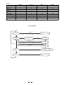
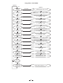
UTILITY MENU
init
Enter/Esc
Load Preset
Factory 1,...,64
User 65,...,128
Enter/Esc
Store Preset
Enter
User
65,...,128
Edit Name 1
Esc
Esc
Edit Name 2
Esc
Up/Down
Enter/Esc
Midi Setup
Enter
Enter
Edit Name 6
Channel OFF,1,...,16,OMNI
0,...,127
0=Mute; 127=0dB
Output Att.
18
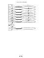
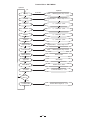
Reverb Effect - EDIT MENU
Start
Up/Down
Enter/Esc
No
Low Pass Input
1KHz,..,16KHz,Bypass; step 1/3 oct
H Damp
1KHz,..,16KHz,Bypass; step 1/3 oct
L Damp
Bypass,50Hz,..,1KHz; step 1/3 oct
PreDlelay Riv
0,...,254 ms step 2ms
PreDlelay ER
0,...,254 ms step 2ms
PreDlelay FR
0,...,254 ms step 2ms
Diffusion
0,...,127; Min,...,Max
Density
0,...,127; Min,...,Max
Decay
0,...,127; Min,...,Max
High Pass Eff.
Bypass,50Hz,..,1KHz; step 1/3 oct
Loe Pass Eff.
1KHz,..,16KHz,Bypass; step 1/3 oct
Tunging
Min=0 Max=127
%VolumeER
Volume Early Reflection; 0,...,127
% Volume FR
Volume Fast Reflection; 0,...,127
% Volume Riv
Volume Reverb; 0,...,127
% Vol Effect
% Volume Effect; 0,...,100
Effect=
DRY?
Yes
% Volume Dir
Volume direct signal; 0,...,127
19
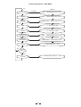
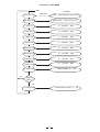
Reverse Effect - EDIT MENU
init
Up/Down
Time
No
Enter/Esc
36,...,636 ms step 3ms
PreDelay
0,...,254 ms step 2ms
Density
0,...,127; Min,...,Max
High Pass Eff.
Bypass,50Hz,...,1KHz; step 1/3 oct
Low Pass Eff.
1KHz,...,16KHz,Bypass; step 1/3 oct
Reverse Mode
Linear, Exp, Gated
% Volume Eff.
Volume Effect; 0,...,127
Effect=
DRY ?
Yes
Volume direct signal; 0,...,127
% Volume Dir
20
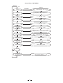
Stereo Delay Effect - EDIT MENU
init
Up/Down
Low Pass Input
No
Enter/Esc
1KHz,...,16KHz,Bypass; step 1/3 oct
H Damp
1KHz,...,16KHz,Bypass; step 1/3 oct
L Damp
Bypass,50Hz,...,1KHz; step 1/3 oct
Time R
0,...,995 ms step 5ms
Time L
0,...,995 ms step 5ms
Decay L
0,...,127; Min,...,Max
Decay R
0,...,127; Min,...,Max
High Pass Eff.
Bypass,50Hz,...,1KHz; step 1/3 oct
Low Pass Eff.
1KHz,...,16KHz,Bypass; step 1/3 oct
Link L+R
OFF, ON
% Vol Eff.
Volume Effect; 0,...,127
Effect=
DRY ?
Yes
Volume direct signal; 0,...,127
% Volume Dir
21
PingPong Delay Effect - EDIT MENU
init
Up/Down
Low Pass Input
Enter/Esc
1KHz,...,16KHz,Bypass; step 1/3 oct
H Damp
1KHz,...,16KHz,Bypass; step 1/3 oct
L Damp
Bypass,50Hz,...,1KHz; step 1/3 oct
Time
0,...,995 ms step 5ms
Decay
0,...,127; Min,...,Max
High Pass Eff.
1KHz,...,16KHz,Bypass; step 1/3 oct
Low Pass Eff.
Bypass,50Hz,...,1KHz; step 1/3 oct
Volume Effect; 0,...,127
% Vol Eff.
No
Effect=
DRY ?
Yes
Volume direct signal; 0,...,127
% Vol Dir
22
Multi Delay Effect - EDIT MENU
Up/Down
init
Up/Down
Low Pass Input
No
Enter/Esc
1KHz,...,16KHz,Bypass; step 1/3 oct
H Damp
1KHz,...,16KHz,Bypass; step 1/3 oct
L Damp
Bypass,50Hz,...,1KHz; step 1/3 oct
Time 1
0,...,995 ms step 5ms
Time 2
0,...,995 ms step 5ms
Time 3
0,...,995 ms step 5ms
Decay 1
0,...,127; Min,...,Max
Decay 2
0,...,127; Min,...,Max
Decay 3
0,...,127; Min,...,Max
Volume 1
0,...,127; Min,...,Max
Volume 2
0,...,127; Min,...,Max
Volume 3
0,...,127; Min,...,Max
Panpot 1
0,...,127; (MinL Max R,...,Min R Max L
Panpot 2
0,...,127; (MinL Max R,...,Min R Max L
Panpot 3
0,...,127; (MinL Max R,...,Min R Max L
% Vol Eff.
Volume Effect; 0,...,127
Effect=
DRY ?
Yes
Volume direct signal; 0,...,127
% Volume Dir
23
Chorus Effect - EDIT MENU
Up/Down
init
Up/Down
H Damp
Enter/Esc
1KHz,...,16KHz,Bypass; step 1/3 oct
L Damp
No
Bypass,50Hz,...,1KHz; step 1/3 oct
Rate L
0,...,128; Min,...,Max
Rate R
0,...,128; Min,...,Max
Depth L
0,...,240; Min,...,Max
Depth R
0,...,240; Min,...,Max
High Pass Eff.
Bypass,50Hz,...,1KHz; step 1/3 oct
Low Pass Eff.
1KHz,...,16KHz,Bypass; step 1/3 oct
Phase Chorus
Direct, Invers
Type Osc
Sin, Ramp
Effect Mode
Stereo, Mono, Sum
Effect=
DRY ?
Yes
Volume direct signal; 0,...,127
% Volume Dir
24
Flange Effect - EDIT MENU
Up/Down
init
Up/Down
H Damp
Enter/Esc
1KHz,...,16KHz,Bypass; step 1/3 oct
Bypass,50Hz,...,1KHz; step 1/3 oct
L Damp
No
Rate L
0,...,128; Min,...,Max
Rate R
0,...,128; Min,...,Max
Depth L
0,...,240; Min,...,Max
Depth R
0,...,240; Min,...,Max
Decay L
0,...,127; Min,...,Max
Decay R
0,...,127; Min,...,Max
High Pass Eff.
Bypass,50Hz,...,1KHz; step 1/3 oct
Low Pass Eff.
1KHz,...,16KHz,Bypass; step 1/3 oct
Phase Tremolo
Direct, Invers
Type Osc
Sin, Ramp
Effect Mode
Stereo, Mono, Sum
% Volume Eff
Volume Effect; 0,...,127
Effect=
DRY ?
Yes
Volume direct signal; 0,...,127
% Volume Dir
25
Tremolo Effect - EDIT MENU
Up/Down
init
Up/Down
H Damp
Enter/Esc
1KHz,...,16KHz,Bypass; step 1/3 oct
L Damp
No
Bypass,50Hz,...,1KHz; step 1/3 oct
Rate L
0,...,128; Min,...,Max
Rate R
0,...,128; Min,...,Max
Depth L
0,...,240; Min,...,Max
Depth R
0,...,240; Min,...,Max
High Pass Eff.
Bypass,50Hz,...,1KHz; step 1/3 oct
Low Pass Eff.
1KHz,...,16KHz,Bypass; step 1/3 oct
Phase Chorus
Direct, Invers
Type Osc
Sin, Ramp
Effect Mode
Stereo, Mono, Sum
% Vol Eff
% Volume Effect; 0,...,127
Effect=
DRY ?
Yes
Volume direct signal; 0,...,127
% Volume Dir
26
Leslie Effect - EDIT MENU
Start
Low Pass Cyl
Up/Down
Enter/Esc
50Hz,..,16KHz,Bypass; step 1/3 oct
High Pass Horn
No
Bypass,50Hz,.. ,16KHz; step 1/3 oct
Rate Cyl
0,...,128; Min ,..,Max
Rate Horn
0,...,128; Min ,..,Max
Depth Cyl
0,...,240; Min ,..,Max
Depth Horn
0,...,240; Min ,..,Max
Mod Amp Cyl
0,...,127; Min ,..,Max
Mod Amp Horn
0,...,127; Min ,..,Max
Volume Cyl
0,...,127; Min ,..,Max
Volume Hron
0,...,127; Min ,..,Max
% Volume Eff
% Volume Effect; 0,....,100
Effect=
DRY ?
Yes
% Volume direct signal; 0,...,127
% Volume Dir
27
Effect & Parameter
Reverb
Revers
St_Dly
Pp_Dly
Mt_Dly
Low Pass
Input
H-Damp
Low Pass
Input
H-Damp
H-Damp
H-Damp
H-Damp
L-Damp
L-Damp
L-Damp
Chorus
Flanger
Tremolo
Leslie
Time
1
Low Pass
Input
H-Damp
PreDelay
Low Pass
Input
H-Damp
2
L-Damp
Density
L-Damp
L-Damp
L-Damp
Rate L
Rate L
Rate L
Rate Cyl
3
High Pass
eff
Low Pass
eff
Revers
Mode
% Vol Eff
Time L
Time
Time1
Rate R
Rate R
Rate R
Rate Horn
Time R
Decay
Time 2
Depth L
Depth L
Depth L
Depth Cyl
Decay L
Depth R
Depth R
Depth R
Depth Horn
Decay 1
Density
% Vol Dir
High Pass
eff
Delay R
8
Decay
High Pass
eff
Low Pass
eff
Link L+R
% Vol Dir
Decay 3
High Pass
eff
Low Pass
eff
Phase eff
Delay L
7
High Pass
eff
Low Pass
eff
% Vol Eff
Time3
6
PreDelay
E.R.
PreDelay
P.R.
PreDelay
Rev
Diffusion
Volume 1
Type Osc
% Vol Eff
Volume 2
% Vol Dir
0
4
5
Decay R
Low Pass
Cyl
High Pass
Horn
Phase eff
Type Osc
Vol Horn
Mode Eff
High Pass
eff
Low Pass
eff
Phase eff
Mod Amp
Cyl
Mod Amp
Horn
Vol Cyl
Mode eff
% Vol Eff
Volume 3
% Vol Eff
Type Osc
% Vol Eff
% Vol Dir
12 % Vol E.R
PanPot 1
% Vol Dir
Mode eff
% Vol Dir
13 % Vol F.R
PanPot 2
% Vol Eff
14 % Vol Rev
PanPot 3
% Vol Dir
15 % Vol Eff
16 % Vol Dir
% Vol Eff
% Vol Dir
High Pass
eff
10 Low Pass
eff
11 Turning
9
28
Decay 2
Delay R
MIDI
Change Preset
st
MIDI 1 Byte - PROGRAM CHANGE
MIDI 2nd Byte - 0,...,127
nd
MIDI 2 byte
Preset
Legend
0,...,7
8,...,15
16,...,23
24,...,27
28,..,33
34,...,37
38,...,41
42,...,49
50,...,55
56,...,59
60,...,63
64,...,127
Reverb - Room
Reverb - Hall
Reverb - Plate
Reverse
Stereo Delay
Pingpong Delay
Multi Delay
Chorus
Flanger
Tremolo
Leslie
User
Preset Custom Effect 1
Preset Custom Effect 1
Preset Custom Effect 1
Preset Custom Effect 2
Preset Custom Effect 3
Preset Custom Effect 4
Preset Custom Effect 5
Preset Custom Effect 6
Preset Custom Effect 7
Preset Custom Effect 8
Preset Custom Effect 9
Preset User
Change Parameter
MIDI 1st Byte - CONTROL CHANGE(MAX FREQUENCY CHANGES: 6 SECONDS)
MIDI 2nd byte
14
7
MIDI 2nd byte
15
16
17
18
19
20
21
22
23
24
25
26
27
28
29
30
31
Status
MIDI 3rd byte
Digital Mix
Output Att
0,1
0,...,127
Dry / Wet
Master output volume (for all effects)
Reverb
MIDI 3rd byte
Legend
Low Pass Input
H-Damp
L-Damp
PreDelay Rev
PreDelay E.R.
PreDelay F.R.
Diffusion
Density
Decay
High Pass eff
Low Pass eff
Tuning
% Vol E.R
% Vol F.R
% Vol Rev
% Vol Eff
% Vol Dir
0,...,13
0,...,13
0,...,14
0,...,127
0,...,127
0,...,127
0,...,127
0,...,127
0,...,127
0,...,14
0,...,13
0,...,127
0,...,127
0,...,127
0,...,127
0,...,100
0,...,127
1KHz,..,16KHz,Bypass; step 1/3 oct
1KHz,..,16KHz,Bypass; step 1/3 oct
Bypass,50Hz,..,1KHz; step 1/3 oct
0,...,254 ms step = 2ms
0,...,254 ms step = 2ms
0,...,254 ms step = 2ms
0,...,127
0,...,127
0,...,127
Bypass,50Hz,..,1KHz; step 1/3 oct
1KHz,..,16KHz,Bypass; step 1/3 oct
Volume Early Reflection
Volume Fast Reflection
tuning
Volume Reverb
Volume of Effect
Volume Direct Signal
29
Legend
MIDI 2
nd
byte
15
16
17
18
19
20
21
22
MIDI 2
nd
byte
15
16
17
18
19
20
21
22
23
24
25
26
MIDI 2 nd byte
15
16
17
18
19
20
21
22
23
MIDI 2 nd byte
15
16
17
18
19
20
21
22
23
24
25
26
27
28
29
30
31
rd
Reverse
MIDI 3 byte
Legend
Time
PreDelay
Density
High Pass eff
Low Pass eff
Revers Mode
% Vol Eff
% Vol Dir
0,...,100
0,...,127
0,...,127
0,...,14
0,...,13
0,1,2
0,...,127
0,...,127
0 / 100ms; Step 1ms
0 / 254 ms; Step 2ms
0,...,127
Bypass,50Hz,..,1KHz; step 1/3 oct
1KHz,..,16KHz,Bypass; step 1/3 oct
Gated, Linear, Exp
Volume of Effect
Volume of Direct Signal
St_Dly
MIDI 3 byte
Low Pass Input
H-Damp
L-Damp
Time L
Time R
Decay L
Decay R
High Pass eff
Low Pass eff
Link L+R
% Vol Eff
% Vol Dir
0,... ,13
0,...,13
0,...,14
0,...,199
0,...,199
0,....127
0,...,127
0,...,14
0,...,13
0,....1
0,...,127
0,...,127
0,...,127
Bypass,50Hz,..,1KHz; step 1/3 oct
1KHz,..,16KHz,Bypass; step 1/3 oct
OFF, ON
Volume of Effect
Volume of Direct Signal
Pp_Dly
MIDI 3 rd byte
Legend
Low Pass Input
H-Damp
L-Damp
Time
Decay
High Pass eff
Low Pass eff
% Vol Eff
% Vol Dir
0,... ,13
0,...,13
0,...,14
0,...,199
0,....127
0,...,14
0,...,13
0,...,127
0,...,127
1KHz,..,16KHz,Bypass; step 1/3 oct
1KHz,..,16KHz,Bypass; step 1/3 oct
Bypass,50Hz,..,1KHz; step 1/3 oct
0 / 995ms; Step 5ms
0,...,127
Bypass,50Hz,..,1KHz; step 1/3 oct
1KHz,..,16KHz,Bypass; step 1/3 oct
Volume of Effect
Volume of Direct Signal
Mt_Dly
MIDI 3 rd byte
Legend
Low Pass Input
H-Damp
L-Damp
Time 1
Time 2
Time 3
Decay 1
Decay 2
Decay 3
Volume 1
Volume 2
Volume 3
PanPot 1
PanPot 2
PanPot 3
% Vol Eff
% Vol Dir
0,... ,13
0,...,13
0,...,14
0,...,199
0,...,199
0,...,199
0,....127
0,...,127
0,....127
0,...,127
0,....127
0,...,127
0,....127
0,...,127
1KHz,..,16KHz,Bypass; step 1/3 oct
1KHz,..,16KHz,Bypass; step 1/3 oct
Bypass,50Hz,..,1KHz; step 1/3 oct
0 / 995ms;Step= 5ms;Time Impulse 1
0 / 995ms;Step= 5ms;Time Impulse 2
0 / 995ms;Step= 5ms;Time Impulse 3
0,...,127 Decay Impulse 1
0,...,127 Decay Impulse 2
0,...,127 Decay Impulse 3
Volume Impulse 1
Volume Impulse 2
Volume Impulse 3
PanPot Impulse 1
PanPot Impulse 2
PanPot Impulse 3
Volume of Effect
Volume of Direct Signal
rd
0,....127
0,...,127
0,....127
30
Legend
1KHz,..,16KHz,Bypass; step 1/3 oct
1KHz,..,16KHz,Bypass; step 1/3 oct
Bypass,50Hz,..,1KHz; step 1/3 oct
0 / 995ms; Step 5ms
0 / 995ms; Step 5ms
nd
MIDI 2 byte
15
16
17
18
19
20
21
22
23
24
25
26
27
nd
MIDI 2 byte
15
16
17
18
19
20
21
22
23
24
25
26
27
28
29
nd
MIDI 2 byte
MIDI 3rd byte
H-Damp
L-Damp
Rate L
Rate R
Depth L
Depth R
High Pass eff
Low Pass eff
Phase Chorus
Type Osc
Effect Mode
% Vol Eff
% Vol Dir
0,... ,13
0,...,14
0,...,128
0,...,128
0,...,240
0,...,240
0,....14
0,....13
0,1
0,1
0,1,2
0,...,127
0,...,127
Flanger
MIDI 3 byte
H-Damp
L-Damp
Rate L
Rate R
Depth L
Depth R
Decay L
Decay R
High Pass eff
Low Pass eff
Phase Chorus
Type Osc
Effect Mode
% Vol Eff
% Vol Dir
0,... ,13
0,...,14
0,...,128
0,...,128
0,...,240
0,...,240
0,...,127
0,...,127
0,....14
0,....13
0,1
0,1
0,1,2
0,...,127
0,...,127
Tremolo
MIDI 3 byte
H-Damp
L-Damp
Rate L
Rate R
Depth L
Depth R
High Pass eff
Low Pass eff
Phase Chorus
Type Osc
Effect Mode
% Vol Eff
% Vol Dir
15
16
17
18
19
20
21
22
23
24
25
26
27
nd
MIDI 2 byte
15
16
17
18
19
20
21
22
23
24
25
26
Chorus
rd
rd
0,... ,13
0,...,14
0,...,128
0,...,128
0,...,240
0,...,240
0,....14
0,....13
0,1
0,1
0,1,2
0,...,127
0,...,127
rd
Leslie
MIDI 3 byte
Low Pass Cyl
High Pass Horn
Rate Cyl
Rate Horm
Depth Cyl
Depth Horn
Mode Amp Cyl
Mode Amp Horn
Vol Cyl
Vol Horn
% Vol Eff
% Vol Dir
0,... ,25
0,...,25
0,...,128
0,...,128
0,...,240
0,...,240
0,...,127
0,...,127
0,...,127
0,...,127
0,...,100
0,...,127
31
Legend
1KHz,..,16KHz,Bypass; step 1/3 oct
Bypass,50Hz,..,1KHz; step 1/3 oct
0,...,128
0,...,128
0,...,240
0,...,240
Bypass,50Hz,..,1KHz; step 1/3 oct
1KHz,..,16KHz,Bypass; step 1/3 oct
Direct/Invers
Sin, Ramp
Stereo, Mono, Sum
Volume of Effect
Volume of Direct Signal
Legend
1KHz,..,16KHz,Bypass; step 1/3 oct
Bypass,50Hz,..,1KHz; step 1/3 oct
0,...,128
0,...,128
0,...,240
0,...,240
0,...,127
0,...,127
Bypass,50Hz,..,1KHz; step 1/3 oct
1KHz,..,16KHz,Bypass; step 1/3 oct
Direct/Invers
Sin, Ramp
Stereo, Mono, Sum
Volume of Effect
Volume of Direct Signal
Legend
1KHz,..,16KHz,Bypass; step 1/3 oct
Bypass,50Hz,..,1KHz; step 1/3 oct
0,...,128
0,...,128
0,...,240
0,...,240
Bypass,50Hz,..,1KHz; step 1/3 oct
1KHz,..,16KHz,Bypass; step 1/3 oct
Direct/Invers
Sin, Ramp
Stereo, Mono, Sum
Volume of Effect
Volume of Direct Signal
Legend
50KHz,..,16KHz,Bypass; step 1/3 oct
Bypass,50Hz,..,1KHz; step 1/3 oct
0,...,128
0,...,128
0,...,240
0,...,240
Modulation Amplitude Cyl
Modulation Amplitude Horn
Volume of Osc Cyl Signal
Volume of Osc Horn Signal
Volume of Effect
Volume of Direct Signal
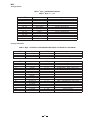
6. TECHNICAL SPECIFICATIONS
Analog Input section
Inputs
Analog variable gain, 1/4" TRS and XLR-F
Input Impedance
Max. input Level
44 kOhms
15 dBu (4.4V RMS)
Sensitivity
-22 dBu (63mV RMS)
Outputs
Output Impedance
Max. output level
Analog variable gain, 1/4" TRS and XLR-M
Analog Output section
<150 Ohms
17 dBu on 600 Ohms (5.5V RMS)
Digital / Analog Interface
Amplitude Response
Signal to Noise Ratio
THD+N
Group Delay
20 Hz - 20 kHz + 0.1 / - 1 dB
90 dB (A wtg. / 20 Hz-20kHz)
0.03 % @ 1kHz -6 dB (VU-meter level)
700
S
Sampling Frequency
Conversion
46.875 kHz
1 bit Sigma-Delta
Processor Speed
12 Mips
DSP Resolution
Control
24 32 bits
Microprocessor
Connections
Sockets
Input/Output/Thru
5-poles DIN (female)
Mode
Photocoupled
Connector type
3-pole IEC, grounded
Type
Mains supply
Servo controlled, stabilized
95-120V /210-240V ,60-50Hz
Power Rating
9W
Alphanumeric LCD Display
VU meter
2 20 characters
7 user keys / 5 LEDs
2 6 LEDs
Size
Standard 19'' rack mounting
Dimensions
Net Weight
483(W)
Digital
MIDI Section
Power Supply
User Interface
Keyboard
Physical
232.5(D)
3.8kg(8.38lb)
32
44(H)mm(19''
9.3''
1.7'')
7. WARRANTY
1. WARRANTY REGISTRATION CARD
To obtain Warranty Service, the buyer should first fill out and return the enclosed Warranty Registration Card within
10 days of the Purchase Date.
All the information presented in this Warranty Registration Card gives the manufacturer a better understanding of
the sales status, so as to purport a more effective and efficient after-sales warranty service.
Please fill out all the information carefully and genuinely, miswriting or absence of this card will void your warranty
service.
2. RETURN NOTICE
2.1 In case of return for any warranty service, please make sure that the product is well packed in its original shipping
carton, and it can protect your unit from any other extra damage.
2.2 Please provide a copy of your sales receipt or other proof of purchase with the returned machine, and give detail
information about your return address and contact telephone number.
2.3 A brief description of the defect will be appreciated.
2.4 Please prepay all the costs involved in the return shipping, handling and insurance.
3. TERMS AND CONDITIONS
3.1
LTO warrants that this product will be free from any defects in materials and/or workmanship for a period
of 1 year from the purchase date if you have completed the Warranty Registration Card in time.
3.2 The warranty service is only available to the original consumer, who purchased this product directly from the
retail dealer, and it can not be transferred.
3.3 During the warranty service, LTO may repair or replace this product at its own option at no charge to you for
parts or for labor in accordance with the right side of this limited warranty.
3.4 This warranty does not apply to the damages to this product that occurred as the following conditions:
Instead of operating in accordance with the user's manual thoroughly, any abuse or misuse of this product.
Normal tear and wear.
The product has been altered or modified in any way.
Damage which may have been caused either directly or indirectly by another product / force / etc.
Abnormal service or repairing by anyone other than the qualified personnel or technician.
And in such cases, all the expenses will be charged to the buyer.
3.5 In no event shall LTO be liable for any incidental or consequential damages. Some states do not allow the exclusion or limitation of incidental or consequential damages, so the above exclusion or limitation may not apply to you.
3.6 This warranty gives you the specific rights, and these rights are compatible with the state laws, you may also
have other statutory rights that may vary from state to state.
33
SEKAKU ELECTRON INDUSTRY (H.K.) CO. LTD.
No.1, Lane 17, Sec. 2, Han Shi West Road, Taichung, 401 TAIWAN
http://www.altoproaudio.com
Tel:886-4-22313737
email: [email protected] Fax:886-4-22346757
All rights reserved to ALTO. All features and content might be changed
without prior notice. Any photocopy, translation, or reproduction of part of this
manual without written permission is forbidden. Copyright c 2004 Sekaku Electron
NF0 0868 -2.2