1
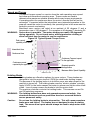
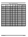
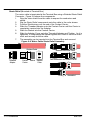
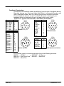
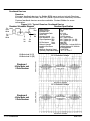
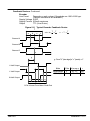
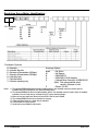
Brushless Servo
Motors
Installation and Operating Manual
6/06
MN1240
Table of Contents
Section 1
General Information . . . . . . . . . . . . . . . . . . . . . . . . . . . . . . . . . . . . . . . . . . . . . . . . . . .
Overview . . . . . . . . . . . . . . . . . . . . . . . . . . . . . . . . . . . . . . . . . . . . . . . . . . . . . . . . .
Limited Warranty . . . . . . . . . . . . . . . . . . . . . . . . . . . . . . . . . . . . . . . . . . . . . . . . . .
Safety Notice . . . . . . . . . . . . . . . . . . . . . . . . . . . . . . . . . . . . . . . . . . . . . . . . . . . . .
Section 2
Installation . . . . . . . . . . . . . . . . . . . . . . . . . . . . . . . . . . . . . . . . . . . . . . . . . . . . . . . . . . .
Overview . . . . . . . . . . . . . . . . . . . . . . . . . . . . . . . . . . . . . . . . . . . . . . . . . . . . . . . . .
Location . . . . . . . . . . . . . . . . . . . . . . . . . . . . . . . . . . . . . . . . . . . . . . . . . . . . . . . . . .
Mounting . . . . . . . . . . . . . . . . . . . . . . . . . . . . . . . . . . . . . . . . . . . . . . . . . . . . . . . . .
Alignment . . . . . . . . . . . . . . . . . . . . . . . . . . . . . . . . . . . . . . . . . . . . . . . . . . . . . . . .
Receiving . . . . . . . . . . . . . . . . . . . . . . . . . . . . . . . . . . . . . . . . . . . . . . . . . . . . . . . .
Storage . . . . . . . . . . . . . . . . . . . . . . . . . . . . . . . . . . . . . . . . . . . . . . . . . . . . . . . . . .
Unpacking . . . . . . . . . . . . . . . . . . . . . . . . . . . . . . . . . . . . . . . . . . . . . . . . . . . . . . . .
Handling . . . . . . . . . . . . . . . . . . . . . . . . . . . . . . . . . . . . . . . . . . . . . . . . . . . . . . . . .
Repairs . . . . . . . . . . . . . . . . . . . . . . . . . . . . . . . . . . . . . . . . . . . . . . . . . . . . . . . . . .
Prevent Electrical Noise . . . . . . . . . . . . . . . . . . . . . . . . . . . . . . . . . . . . . . . . . . . .
Shaft Loads . . . . . . . . . . . . . . . . . . . . . . . . . . . . . . . . . . . . . . . . . . . . . . . . . . . . . . .
Life Determination . . . . . . . . . . . . . . . . . . . . . . . . . . . . . . . . . . . . . . . . . . . . . . . . .
Speed and Torque . . . . . . . . . . . . . . . . . . . . . . . . . . . . . . . . . . . . . . . . . . . . . . . . .
Holding Brake . . . . . . . . . . . . . . . . . . . . . . . . . . . . . . . . . . . . . . . . . . . . . . . . . . . . .
Electrical Connections . . . . . . . . . . . . . . . . . . . . . . . . . . . . . . . . . . . . . . . . . . . . .
Overview . . . . . . . . . . . . . . . . . . . . . . . . . . . . . . . . . . . . . . . . . . . . . . . . . . . .
Motor Lead Termination . . . . . . . . . . . . . . . . . . . . . . . . . . . . . . . . . . . . . . .
Feedback Termination . . . . . . . . . . . . . . . . . . . . . . . . . . . . . . . . . . . . . . . . .
Feedback Devices . . . . . . . . . . . . . . . . . . . . . . . . . . . . . . . . . . . . . . . . . . . .
Brushless Servo Motor Identification . . . . . . . . . . . . . . . . . . . . . . . . . . . . . . . . .
MN1240
1-1
1-1
1-1
1-2
2-1
2-2
2-2
2-2
2-2
2-3
2-3
2-3
2-3
2-3
2-3
2-4
2-6
2-8
2-8
2-10
2-10
2-10
2-12
2-13
2-15
Table of Contents i
ii Table of Contents
MN1240
Section 1
General Information
Overview This manual contains general procedures that apply to Baldor Motor products.
Important:
Be sure to read and understand the Safety Notice statements in this manual.
For your protection, do not install, operate or attempt to perform maintenance
procedures until you understand the Warning and Caution statements. A
Warning statement indicates a possible unsafe condition that can cause harm
to personnel. A Caution statement indicates a condition that can cause
damage to equipment.
This instruction manual is not intended to include a comprehensive
listing of all details for all procedures required for installation, operation
and maintenance. This manual describes general guidelines that apply
to most of the motor products shipped by Baldor. If you have a question
about a procedure or are uncertain about any detail, Do Not Proceed.
Please contact your Baldor distributor for more information or
clarification.
Before you install, operate or perform maintenance, become familiar with the
following:
S
NEMA Publication ICS16, Motion/Position Control Motors; Controls; and
Feedback Devices.
S
The National Electrical Code
S
Local codes and Practices
Limited Warranty
1.
2.
3.
MN1240
Baldor Electric motors are warranted for a period of one (1) year, from date
of shipment from the factory or factory warehouse against defects in
material and workmanship. To allow for stocking and/or fabrication period
and to provide one year of actual service, the warranty period is extended
for an additional period of six (6) months for a total of eighteen (18) months
from the original date of shipment from the factory or factory warehouse
stock. In no case will the warranty period be extended for a longer period.
Baldor extends this limited warranty to each buyer of the electric motor for
the purpose of resale and to the original purchaser for use.
Baldor will, at its option repair or replace a motor which fails due to
defects in material or workmanship during the warranty period if:
a.
the purchaser presents the defective motor at or ships it prepaid to,
the Baldor plant in Fort Smith, Arkansas or one of the Baldor
Authorized Service Centers and
b.
the purchaser gives written notification concerning the motor and
the claimed defect including the date purchased, the task
performed by the Baldor motor and the problem encountered.
Baldor will not pay the cost of removal of any electric motor from any
equipment, the cost of delivery to Fort Smith, Arkansas or a Baldor
Authorized Service Center, or the cost of any incidental or consequential
damages resulting from the claimed defects. (Some states do not allow
the exclusion or limitation of incidental or consequential damages, so the
above exclusion may not apply to you.) Any implied warranty given by
laws shall be limited to the duration of the warranty period hereunder.
(Some states do not allow limitations on how long an implied warranty
lasts, so the above limitation may not apply to you.)
General Information 1-1
4.
5.
6.
7.
Baldor Authorized Service Centers, when convinced to their satisfaction
that a Baldor motor developed defects in material or workmanship within
the warranty period, are authorized to proceed with the required repairs to
fulfill Baldor’s warranty when the cost of such repairs to be paid by Baldor
does not exceed Baldor’s warranty repair allowance. Baldor will not pay
overtime premium repair charges without prior written authorization.
The cost of warranty repairs made by centers other than Baldor
Authorized Service Centers WILL NOT be paid unless first authorized in
writing by Baldor.
Claims by a purchaser that a motor is defective even when a failure results
within one hour after being placed into service are not always justified.
Therefore, Baldor Authorized Service Centers must determine from the
condition of the motor as delivered to the center whether or not the motor
is defective. If in the opinion of a Baldor Authorized Service Center, a motor
did not fail as a result of defects in material or workmanship, the center is
to proceed with repairs only if the purchaser agrees to pay for such repairs.
If the decision is in dispute, the purchaser should still pay for the repairs and
submit the paid invoice and the Authorized Service Center’s signed service
report to Baldor for further consideration.
This warranty gives you specific legal rights, and you may also have
other rights which vary from state to state.
Safety Notice: This equipment contains high voltage! Electrical shock can cause serious
or fatal injury. Only qualified personnel should attempt installation, operation
and maintenance of electrical equipment.
Be sure that you are completely familiar with NEMA publications ICS16 and
MG-2, safety standards for construction and guide for selection, installation
and use of electric motors and generators, the National Electrical Code and
local codes and practices. Unsafe installation or use can cause conditions
that lead to serious or fatal injury. Only qualified personnel should attempt
the installation, operation and maintenance of this equipment.
WARNING: Do not use these motors in the presence of flammable or combustible
vapors or dust. These motors are not designed for atmospheric
conditions that require explosion proof construction.
WARNING: Do not touch electrical connections before you first ensure that power
has been disconnected. Electrical shock can cause serious or fatal
injury. Only qualified personnel should attempt the installation,
operation and maintenance of this equipment.
WARNING: Be sure the system is properly grounded before applying power. Do not
apply power before you ensure that all grounding instructions have
been followed. Electrical shock can cause serious or fatal injury.
National Electrical Code and Local codes must be carefully followed.
WARNING: Avoid extended exposure to machinery with high noise levels. Be sure
to wear ear protective devices to reduce harmful effects to your hearing.
1-2 General Information
MN1240
WARNING: The holding brake alone does not guaranty personnel safety. Use
structural measures such as protective fences or a second brake to
secure personnel safety.
WARNING: This equipment may be connected to other machinery that has rotating
parts or parts that are driven by this equipment. Improper use can
cause serious or fatal injury. Only qualified personnel should attempt to
install operate or maintain this equipment.
WARNING: Do not by-pass or disable protective devices or safety guards. Safety
features are designed to prevent damage to personnel or equipment.
These devices can only provide protection if they remain operative.
WARNING: Avoid the use of automatic reset devices if the automatic restarting of
equipment can be hazardous to personnel or equipment.
WARNING: Be sure the load is properly coupled to the motor shaft before applying
power. The shaft key must be fully captive by the load device. Improper
coupling can cause harm to personnel or equipment if the load
decouples from the shaft during operation.
WARNING: Use proper care and procedures that are safe during handling, lifting,
installing, operating and maintaining operations.
Improper methods may cause muscle strain or other harm.
WARNING: Before performing any motor maintenance procedure, be sure that the
equipment connected to the motor shaft cannot cause shaft rotation. If
the load can cause shaft rotation, disconnect the load from the motor
shaft before maintenance is performed. Unexpected mechanical rotation
of the motor parts can cause injury or motor damage.
WARNING: Disconnect all electrical power from the motor windings and accessory
devices before disassembly of the motor.
Electrical shock can cause serious or fatal injury.
WARNING: Ensure all electrical connections are securely made. High voltage may
be present and high motor speeds may result from a broken connection.
WARNING: Pacemaker Danger − Magnetic and electromagnetic fields in the vicinity
of current carrying conductors and permanent magnet motors can result
in a serious health hazard to persons with cardiac pacemakers, metal
implants and hearing aids.
WARNING: Dangerous movements can occur when a motor is improperly
connected or a fault occurs. Be careful during start−up, troubleshooting
and maintenance procedures to avoid injury.
WARNING: Severe burn is possible. The motor winding can reach 155 degrees C
during operation. Do not touch motor without protective clothing or
allow sufficient time for motor to cool to avoid burns.
MN1240
General Information 1-3
Safety Notice Continued
Caution:
To prevent premature equipment failure or damage, only qualified
maintenance personnel should perform maintenance.
Caution:
Do not lift the motor and its driven load by the motor lifting hardware.
The motor lifting hardware is adequate for lifting only the motor.
Disconnect the load from the motor shaft before moving the motor.
Caution:
To prevent equipment damage, be sure that the control is fused for the
maximum motor rated amps listed on the rating plate.
Caution:
If a HI POT test (High Potential Insulation test) must be performed, follow
the precautions and procedure in NEMA MG-1 and MG-2 standards to
avoid equipment damage.
Caution:
Do not perform dielectric withstand tests on any feedback device or
motor control as damage may result.
Caution:
Motor housings get very hot during normal operation. Do not touch the
motor after use until it has had sufficient time to cool. Severe burns
may result from touching the motor after use.
Caution:
Do not use the holding brake to stop motion. This will cause premature
brake wear and failure. The brakes are not designed to stop a rotating
load. The servo drive inputs should always be used to stop motor shaft
rotation.
Caution:
The AC servo motor is not intended to be connected directly to the AC
mains. Do not connect AC Mains directly to BSM AC Servo Motors.
If you have any questions or are uncertain about any statement or procedure,
or if you require additional information please contact your Baldor distributor
or an Authorized Baldor Service Center.
1-4 General Information
MN1240
Section 2
Installation
Overview Installation should conform to the National Electrical Code as well as local
codes and practices. When other devices are coupled to the motor shaft, be
sure to install protective devices to prevent accidents. Some protective
devices include, coupling, belt guard, chain guard, shaft covers etc. These
protect against accidental contact with moving parts. Machinery that is
accessible to personnel should provide further protection in the form of guard
rails, screening, warning signs etc.
Location The motor should be installed in an area that is protected from direct sunlight,
corrosives, harmful gases or liquids, dust, metallic particles, and vibration.
Exposure to these can reduce the operating life and degrade performance.
Be sure to allow clearance for ventilation and access for cleaning, repair,
service and inspections. Ventilation is extremely important. Be sure the area
for ventilation is not obstructed. Obstructions will limit the free passage of air.
Motors get warm and the heat must be dissipated to prevent damage.
These motors are not designed for atmospheric conditions that require
explosion proof operation. They must NOT be used in the presence of
flammable or combustible vapors or dust.
Mounting The motor must be securely installed to a rigid foundation or mounting surface
to minimize vibration and maintain alignment between the motor and shaft
load. Failure to provide a proper mounting surface may cause vibration,
misalignment and bearing damage. For mounting dimensions, refer to
http://www.baldor.com/products/servo_motors.asp and provide adequate
clearance.
Alignment Accurate alignment of the motor with the driven equipment is extremely
important.
1.
Direct Coupling
For direct drive, use flexible couplings if possible. Consult the drive or
equipment manufacturer for more information. Mechanical vibration and
roughness during operation may indicate poor alignment. Use dial
indicators to check alignment. The space between coupling hubs should
be maintained as recommended by the coupling manufacturer.
2.
End-Play Adjustment
The axial position of the motor frame with respect to its load is also
extremely important. The motor bearings are not designed for excessive
external axial thrust loads. Improper adjustment will cause failure.
Figure 2-1 Mounting Orientation
These mounting orientations
are allowed.
MN1240
Installation 2-1
Receiving Each Baldor Electric Motor is thoroughly tested at the factory and carefully
packaged for shipment. When you receive your motor, there are several
things you should do immediately.
1.
Observe the condition of the shipping container and report any damage
immediately to the commercial carrier that delivered your motor.
2.
Verify that the part number of the motor you received is the same as the
part number listed on your purchase order.
Storage
If the motor is not put into service immediately, the motor must be stored in a
clean, dry and warm location. If the parts are not put into service immediately,
store them in a clean, dry and warm location. The motor must be protected
from moisture and condensation. Storage area should be a dust free
environment, maintained −25 degC to +85 degC and less than 90% relative
humidity non−condensing.
Unpacking
Each Baldor motor is packaged for ease of handling and to prevent entry
of contaminants.
1.
To avoid condensation inside the motor, do not unpack until the motor
has reached room temperature. (Room temperature is the temperature
of the room in which it will be installed). The packing provides insulation
from temperature changes during transportation.
2.
When the motor has reached room temperature, remove all protective
wrapping material from the motor.
Handling Use proper care and procedures that are safe during handling, lifting,
installing, operating and maintenance operations. Improper methods may
cause muscle strain or other harm.
Repairs
Baldor will not share any responsibility for damage caused by customer
attempt to repair or modify a motor. Consult Baldor for any service.
Prevent Electrical Noise
Electro−Magnetic−Interference (EMI), commonly called “electrical noise” may
adversely affect motor performance by introducing stray signals. Effective
techniques to reduce or prevent EMI include AC power filters, cable shielding,
separating signal wires from power wires and good grounding techniques.
Effective AC power filtering can be achieved by using properly installed
“Isolated AC Power Transformers” or “AC Line Filters”. Other techniques are:
S
Install motor cables and signal wires in separate conduits.
S
Do not route motor cables and signal wires in parallel. Separate cables
by at least 1 foot for every 30 feet of run.
S
Cross signal and power wires at 90 degree angles to prevent inductive
noise coupling.
S
Do not route signal wires over the vent openings of the servo drives.
S
Ground all equipment using a single point ground system.
S
Keep wires as short as possible.
S
Ground both ends of the encoder cable and use twisted pair wires.
S
Use shielded motor cables to prevent EMI from other equipment.
2-2 Installation
MN1240
Shaft Loads The motors can be damaged by excessive shaft loads. This may shorten
the motor’s service life. The motor warranty is also voided for excessive shaft
load related failures.
The maximum allowable radial force ( F radial max ) depends on the shaft load. It
is determined by (distance x force) and the output shaft design (plain shaft or
shaft with keyway). When motor shaft has both a radial load and an axial
load, axial load rating = 44% of radial load rating listed. Should questions
arise contact [email protected]
Figure 2-2 Radial Load Capacity
Notes:
1) Solid lines are based on L10 = 20,000 hours.
2) Dashed line is based on 104 load peaks @
110% of rated torque.
X"
(Radial Force)
MN1240
Installation 2-3
Figure 2-2 Radial Load Capacity Continued
2-4 Installation
MN1240
Life Determination
How Life is Determined
A life estimate is a calculated, statistical expectancy and is defined as the
length of time, or the number of revolutions, until fatigue develops. This life
depends on many different factors such as loading, speed, lubrication,
operating temperature, contamination, plus other environmental factors. It’s
impossible to predict precisely.
Statistical calculation estimates are based upon L10 life. This is the life that 90
percent of a group, of apparently identical parts, will reach or exceed. Typical
bearing radial load capacity curves presented in the literature are based upon
bearing L10 life of 20,000 hours.
Using the Curves
First determine your load (or force), location (or distance) from the bearing the
load will be applied, and speed (or RPM). Typical bearing radial load capacity
curves presented in the literature are based upon bearing L10 life of 20,000
hours for a BSM80 Motor, (Figure 2-3). Second, plot these points on the
curve. For example, a force of 80 lbs (352 N), applied 1 inch (25mm) from the
bearing, with a motor speed of 2,000 RPM, would relate to a bearing L10 life
estimate of 20,000 hours.
Figure 2-3
X"
(Radial Force)
Operating 24 hours / day, which is 8500 hours, this would provide a L10 life
estimate of: (20,000 hours) (8500 hours/yr)=2.35yrs.
If Plotted Point Does Not Match your RPM
Many times the point plotted (force and distance), is not specifically on your
applications speed curve, so an estimate for life is calculated as follows:
L 10 +
Where:
MN1240
ǒ16667
ǓxǒCFǓ
S
3
L10 = 20,000 hours
S = RPM
C = capacity of system
F = Force or Load (lb)
Installation 2-5
Example:. Provide an estimate L10 life for a BSM90 motor with a radial load or
force of 130 lbs (570 N) located 3” (76mm) from the bearing. Operating speed
is 1000 RPM.
1.
Determine the systems capacity − at the distance for our application. To
do this, refer to Figure 2-4 and read information from the curve:
a.
Locate our distance (3”) on the X axis.
b.
Pick a speed (8,000 RPM) and locate the intersect with the 3”.
c.
Read the force (100 lbs) on the Y axis.
Figure 2-4 BSM90 Load Capacity Curves
X"
Step 1c
(Radial Force)
Step 1b
Step 1a
d.
Next, insert these numbers into equation (1) above and solve for
capacity “C” (round off for clarity):
x 10 Ǔxǒ C Ǔ
ǒ16667
ǓxǒCFǓ + ǒ168 x10
100
S
20, 000 + ǒ16667Ǔxǒ C Ǔ
8000
100
3
3
L 10 +
3
3
3
2.
C + 2125
Now that capacity is known, it is possible to estimate L10 with the
applications load of 130 lbs (570 N) and 1000 RPM.
L 10 +
ǒ16667
ǓxǒCFǓ
S
3
+
x 10 Ǔxǒ2125Ǔ
ǒ161 x10
130
3
3
3
+ 72, 795 hours
This relates to 72,795 hours / 8500 hours/yr = 8.56 years.
Conclusion
Life is a statistical calculation based upon 90 percent of identical parts
reaching or exceeding an estimate. It depends on many different factors and
is impossible to predict precisely, however calculations provide a guideline.
Motor Poles
BSM50/63/80 Series motors are 4 pole (2 pole pair)
BSM90/100 Series motors are 8 pole (4 pole pair)
2-6 Installation
MN1240
Speed and Torque
The speed−torque curves for a motor show the safe operating area, speed
limit area and intermittent operating area. These curves are used to
determine the maximum useable speeds with known torque requirements.
If operating within the continuous area, the motor’s thermal limit will not be
exceeded. If operated within the intermittent area (extended operation in this
area will cause the motor to overheat), the operating time in this area must be
limited to prevent overheating.
Brushless servo motors are rated at an ambient of 25 degrees C and a
temperature rise of 130 degrees C. For operation at 40 degrees C derate by 6%.
WARNING: Severe burn is possible. The motor winding can reach 155 degrees C
during operation. Do not touch motor without protective clothing or
allow sufficient time for motor to cool to avoid burns.
Figure 2-5 Typical Speed−Torque Curve
Peak current
capability of the motor
Intermittent Area
Continuous Area
Continuous Torque at speed
for the application
Continuous current
required by the application
Required speed for
the application
Maximum Motor Speed Capability
Holding Brake
Holding brakes are offered as options for servo motors. These brakes are
designed to hold the motor shaft at 0 RPM (to rated brake holding torque).
The purpose of the holding brake is to hold the servo axis when power to the
machine is turned off. The holding brake uses the “electric release” principle.
Apply 24VDC to the brake causes the brake to release and let the motor shaft
rotate. Loss of power causes the brake to hold the motor shaft.
The machine controller controls the holding brake. This ensures correct On
and Off switching sequence.
WARNING: The holding brake alone does not guarantee personnel safety. Use
structural measures such as protective fences or a second brake to
secure personnel safety.
Caution:
Do not use the holding brake to stop motion. This will cause premature
brake wear and failure. The brakes are not designed to stop a rotating
load. The servo drive inputs should always be used to stop motor shaft
rotation.
MN1240
Installation 2-7
Motor Code
BSM50N−1
BSM50N−2
BSM50N−3
BSM63N−1
BSM63N−2
BSM63N−3
BSM80N−1
BSM80N−2
BSM80N−3
BSM90N−1
BSM90N−2
BSM90N−3
BSM100N−1
BSM100N−2
BSM100N−3
BSM100N−4
BSM80C−1
BSM80C−2
BSM80C−3
BSM90C−1
BSM90C−2
BSM90C−3
BSM100C−1
BSM100C−2
BSM100C−3
BSM100C−4
BSM100C−5
BSM100C−6
2-8 Installation
Table 2-1 Brake Specifications
Brake Holding
Brake
Brake
Torque
Voltage Current
Watts
(lb−in / N−m)
VDC
AMPS
13/1.4
10.1
24
0.5
13/1.4
10.1
24
0.5
13/1.4
10.1
24
0.5
18/2
11.9
24
0.6
18/2
11.9
24
0.6
18/2
11.9
24
0.6
40/4.5
19.7
24
0.7
40/4.5
19.7
24
0.7
40/4.5
19.7
24
0.7
77/8.7
22.5
24
0.9
140/15.8
22.5
24
0.9
140/15.8
22.5
24
0.9
200/22.5
31.4
24
1.3
200/22.5
31.4
24
1.3
350/39.5
33.7
24
1.4
350/39.5
33.7
24
1.4
30/3.3
19.7
24
0.8
30/3.3
19.7
24
0.8
30/3.3
19.7
24
0.8
77/8.7
22.5
24
0.9
77/8.7
22.5
24
0.9
77/8.7
22.5
24
0.9
200/22.5
31.4
24
1.3
200/22.5
31.4
24
1.3
200/22.5
31.4
24
1.3
200/22.5
31.4
24
1.3
350/39.5
33.7
24
1.4
350/39.5
33.7
24
1.4
Brake Times (msec)
Pull−out
Pull−in
(with Diode)
18.6
55
18.6
55
18.6
55
33.5
33.8
33.5
33.8
33.5
33.8
34.5
79.3
34.5
79.3
34.5
79.3
64.1
73.6
64.1
73.6
64.1
73.6
83.9
188
83.9
188
157.3
220
157.3
220
34.5
79.3
34.5
79.3
34.5
79.3
64.1
73.6
64.1
73.6
64.1
73.6
83.9
188
83.9
188
83.9
188
83.9
188
157.3
220
157.3
220
MN1240
Electrical Connections
Overview Figure 2-6 shows typical connections to a control. Note all wiring
should be 600volts.
Figure 2-6 Typical Connections to Motor Control
Motor
Temperature
Switch
Motor Temperature Input
Holding
Brake
Holding Brake Connector
Shielded
Twisted Pair Wire
Motor Ground Wire
Motor
Connector
Shielded Motor Cable
V W
U
G
Feedback
Connector
AC Motor
Feedback
Control
Motor
Shielded
Twisted Pair Wire
All wiring should have 600V rated insulation.
Single Point Ground
Motor Lead Termination
Motor leads are normally terminated using a Connector or Terminal Box (see
Figure 2-7) or Flying Leads. When no termination is provided and the motor
leads just exit the motor housing, this is called “Flying Leads”. For flying
leads, refer to the motor packing list to determine the lead configuration.
Figure 2-7 Motor Termination
8 Pin
Function
Pin
Function
Pin
Thermal Switch
Thermal Switch
Brake
Brake
U
Ground
W
V
MN1240
A
B
C
D
1
2
3
4
C
D
3
B
A
4
1
2
Connector Termination
Thermal Switch
Thermal Switch
Brake
Brake
U
V
W
Ground (P.E.)
1
2
3
4
U
V
W
Screw
Terminal Box Termination
Installation 2-9
Strain Relief (Mounted at Terminal Box)
The motor cable is terminated at the Terminal Box using a Shielded Strain Relief
Connector. Figure 2-8 shows the components.
1.
Strip the outer shield from the cable to expose the conductors and
shield.
2.
Slip the Strain Relief components onto the cable in the order shown.
3.
Fold the Shield wires over the end of the Contact Carrier.
4.
Slide the Threaded Adapter onto the Contact Carrier until the Carrier is
completely inserted into the Adapter.
5.
Slide the Gasket into the Contact Carrier.
6.
Slide the Adapter Cover onto the Threaded Adapter and Tighten. As it is
tightened, it compresses the Gasket against the Cable to form the strain
relief and securely hold the cable.
7.
The assembly can be inserted into the Terminal Box and secured.
Figure 2-8 Motor Cable Strain Relief Assembly
Shielded Cable
Threaded
Adapter
Contact
Carrier
Gasket Adapter
Cover
Assemble Parts onto Cable
Fold Shield wires over Contact Carrier
Assembled
2-10 Installation
MN1240
Feedback Termination
Connections for Feedback cables are different for each type of feedback device.
Standard devices are: Resolver, Halls (Hall Effect), Incremental Encoder with
Halls, Absolute Encoder, and SSI (Serial Synchronous Interface) encoder.
Custom feedback devices are also available. Request a drawing of your
feedback device to determine the pin−out and/or wire color codes.
Figure 2-9 Typical Connections to Feedback Termination
Function
Pin
Function
Pin
12 Pin
12 Pin
R1
R2
S1
S3
S2
S4
REF HI
REF LO
COS+
COS−
SINE+
SINE−
Open
Function
DC +5V
Ground
Channel A+
Channel A−
Channel B+
Channel B−
Channel C+
Channel C−
Open
Channel U+
Channel U−
Channel V+
Channel V−
Channel W+
Channel W−
Open
1
2
3
4
5
6
7−12
9
1
2
10
11
3
4
8
12
7
6
5
Resolver
Pin
1
2
3
4
5
6
7
8
9
10
11
12
13
14
15
16
Data−
SIN A+
0V Sensor
COS B+
Clock−
5V Sensor
Clock+
COS B−
+5V 9
D GND
SIN A−
Data+
1
2
3
4
5
6
7
8
Function
Pin
+Vs (5VDC)
0V 2
SSI Clock
NSSI Clock
SSI Data
NSSI Data
1
1 9
2
3
Encoder with Halls
12
11
6
7
4
5
Absolute Encoder
10
11
12
16 Pin
11 1
2
10
12
13 3
16
9
15 14
4
8
5
7
6
8
10
12 Pin
3
4
5
6
1 9
2
3
4
8
10
12
11
6
7
5
Serial Synchronous Interface
For complete control connections/wiring refer to the following manuals:
MN723 − SD23H
MN7423 − H2 Servo
MN1902 − Flex/Flex+DriveII MN1901 − MintDriveII
MN1919 − MicroFlex
MN1240
Installation 2-11
Feedback Devices
Resolver
Common feedback devices for Baldor BSM servo motors include Resolver,
Encoder, Absolute Encoder, and SSI (Serial Synchronous Interface) encoder.
Custom feedback devices are also available. Contact Baldor for more
information.
Figure 2-10 Typical Resolver Feedback Device
Resolver Schematic Diagram
Resolver Specification
R1
Red/
White
S1
Red
R2
Yel/
White
S3
Blk
S2
Yel
S4
Blu
L2=Motor lead L2 (V)
L3=Motor lead L3 (W)
Waveform 1
8 Pole Motor and
2 Pole Resolver
Power Source
Primary Element
Electrical Error
Transformation Ratio
Phase Shift
Accuracy Spread
Input Impedance ZRO
Output Impedance ZSO
ZSS
DC Resistance
Rotor
Stator
Dielectric Strength
Insulation Resistance
Weight
Maximum Operating Speed
Operating Temperature Range
AC 10VRMS 4.5kHz
Rotor
±7%
0.5 ±10%
±8° nominal
12 ARC minutes
90 + j180Ω nominal
220 + j350Ω @ 0° (s1−S3)
210 + j300Ω @ 0° (s1−S3)
46Ω REF
120Ω REF
AC 500 volts, 1 minute 60/50 Hz
100MΩ Minimum DC 500Volts
0.18kg Maximum
10,000 RPM
−55 °C to +150 °C
L2−L3 Generated Voltage
Cosine Signal
L2−L3 Generated Voltage
Waveform 2
4 Pole Motor and
2 Pole Resolver
2-12 Installation
Cosine Signal
MN1240
Feedback Devices Continued
Encoder
Line Count
Depends on unit ordered. Standards are 1000−2500 ppr.
(Custom resolutions are available.)
Supply Voltage 5VDC
Supply Current 250mA maximum
Output
TTL (Line Driver)
Figure 2-11 Typical Encoder Feedback Device
T
a
b
c
a.b.c.d = T " T
4
8
d
e +T"T
2
Channel A
Channel B
Channel C
e
g
g: From U" (rise edge) to c" (center) ±1°
U Hall Output
V Hall Output
Motor
Pole
BSM50/63/80
BSM 90/100
4
8
k,l,m,n,p,q
30° ± 1°
15° ± 1°
r
180°
90°
W Hall Output
k
l
m
r
n
p
q
CCW Viewed From Motor Shaft End
MN1240
Installation 2-13
Brushless Servo Motor Identification
SS = Stainless
Steel
IEC
50
63
80
90
100
NEMA
5N
6N
8N
9N
C
N
1
2
3
4
50
75
etc.
Feedback Options
A = Resolver
D = Absolute Encoder
E = Encoder w/Commutation (1000ppr)
F = Encoder w/Commutation (2500ppr)
H = Hall effect only
T = Tach/Hall effect
Y = Resolver mounting only
Notes:
Accessory Options
Blank
= No Option
M
= No Keyway
N
= DIN 42955−R
O
= DIN 42955−R & No Keyway
P
= Optional Motor Connector on BSM 90/100
(Note: This option available only if
current is 20 amps or less).
Z
= Blower 115 VAC
1) The standard BSM50/63/80 Series includes feedback device, two threaded connectors (metric style) for
feedback and motor terminations, IEC square mounting flange.
2) The standard BSM90/100 Series includes feedback device, one threaded connector (metric style) for feedback,
termination of motor lead wires on terminal block, IEC square mounting flange.
3) Motors do not have shaft seal. Motors will meet IP65 if shaft oil seal is added.
4) The standard BSM50 Series has as standard no−keyway.
5) Cables and flying leads are 1 meter long as standard.
6) Contact Baldor for special options
7) Not all options are available on all models.
2-14 Installation
MN1240
Baldor District Offices
BALDOR ELECTRIC COMPANY
5711 R.S. Boreham Jr. Street
Fort Smith, AR 72901−2400
(479) 646−4711
Fax (479) 648−5792
© Baldor Electric Company
MN1240
Printed in USA
6/06