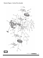
1
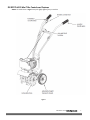
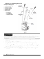
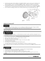
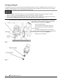
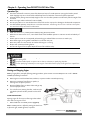
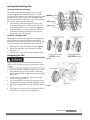
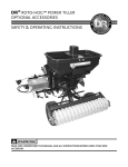
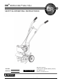
DR® ROTO-HOG™ Mini Tiller SAFETY & OPERATING INSTRUCTIONS Serial No. Order No. Original Language DR Power Equipment Toll-free phone: 1-800-DR-OWNER (376-9637) Fax: 1-802-877-1213 Website: www.DRpower.com Read and understand this manual and all instructions before operating the DR ROTO-HOG Mini Tiller. Table of Contents Chapter 1: Important Safety Considerations .......................................................................................................... 3 Chapter 2: Setting up your DR ROTO-HOG Mini Tiller ........................................................................................ 6 Chapter 3: Operating Your DR ROTO-HOG Mini Tiller ...................................................................................... 11 Chapter 4: Maintaining the DR ROTO-HOG Mini Tiller ..................................................................................... 14 Chapter 5: Troubleshooting .................................................................................................................................. 18 Chapter 6: Parts Lists and Schematic Diagrams .................................................................................................. 20 Conventions used in this manual This indicates a hazardous situation, which, if not avoided, could result in death or serious injury. This indicates a hazardous situation, which, if not avoided, could result in minor or moderate injury. This information is important in the proper use of your machine. Failure to follow this instruction could result in damage to your machine or property. Tip: This is a helpful hint to guide you in getting the most out of your DR ROTO-HOG Mini Tiller. Tools Needed: This indicates you will need a special tool to perform a maintenance function on your Tiller. NOTE: This information may be helpful to you. We have done our utmost to ensure that your DR ROTO-HOG Mini Tiller will be one of the most trouble-free and satisfying pieces of equipment you have ever owned. Please let us know of any questions you may have. We want to answer them as quickly as possible. When you do call, please have your order number, or serial number handy. For technical assistance, please visit our website at www.DRpower.com or call Toll-Free 1-800-DR-OWNER (376-9637) and one of our Technical Support Representatives will be happy to help you. We also hope to hear from you on how much you like your new helper. If you are ever unsure about an action you are about to take, don’t do it, visit our website at www.DRpower.com for help or information. DR Power Equipment reserves the right to discontinue, change, and improve its products at any time without notice or obligation to the purchaser. The descriptions and specifications contained in this manual were in effect at printing. Equipment described within this manual may be optional. Some illustrations may not be applicable to your machine. 2 DR® ROTO-HOG™ Mini Tiller Chapter 1: Important Safety Considerations We want you to enjoy years of safe and productive use from your DR ROTO-HOG Mini Tiller. We do not want you injured, so please take a few moments to read the following instructions for safely operating your new Tiller. Your DR ROTO-HOG Mini Tiller carries a prominent safety label (shown below) to remind you of important information while you are operating the machine. Take a moment to study this label before you operate the machine. Please, immediately replace this label if it should become unreadable due to fading, or otherwise damaged during use of your DR ROTO-HOG Mini Tiller. 35918 Tine Shield Warning Decal Protecting Yourself and Those around You Tragic accidents can occur if the operator is not alert to the presence of children. Children are often attracted to the Tiller and the activity of tilling. Never assume that children will remain where you last saw them. This tilling machine, can cut, and sever parts of your body if they become in contact with the moving Tines. Always take the following precautions when operating the DR ROTO-HOG Mini Tiller: Only allow responsible individuals who have a thorough understanding of these instructions to operate the Tiller. Never allow children to operate the machine. Always wear protective goggles or safety glasses with side shields while tilling to protect your eyes from possible foreign objects thrown from the machine. Wear shoes with non-slip treads when using this machine. If you have safety shoes, we recommend wearing them. Do not use the machine while barefoot or wearing sandals with exposed toes or heels. Avoid wearing loose clothing or jewelry, which can catch on the machine’s moving parts. We recommend wearing long pants and gloves while using this machine. Be sure the gloves fit properly and do not have loose cuffs or drawstrings. Never place your hands, feet, or any part of your body near the Tines when starting the Engine or while the DR ROTOHOG Mini Tiller’s Engine is running. Keep children, other bystanders, and pets away from your work area at all times. Stop the Engine when another person or pet approaches. Before and while pulling the machine backwards, look behind and down for small children and for secure footing. We recommend the use of ear protectors or earplugs rated for at least 20 dba to protect your hearing. CONTACT US AT www.DRpower.com 3 Operating the Tiller Safely Clear the work area of objects that might jam or wrap around the Tines such as glass, large sticks, stones, metal objects, wire, rope, and string-like materials. Use on these objects could damage the DR ROTO-HOG Mini Tiller and/or cause injury. Do not touch the muffler and Engine when the machine is in use as they become very hot and can cause severe burns. The Engine should always be off before adjusting the Wheel Height or Drag Stake. Never, under any conditions, remove, bend, cut, fit, weld, or otherwise alter standard parts on the DR ROTO-HOG Mini Tiller. This includes all shields and guards. Modifications to your machine could cause personal injuries and property damage and will void your warranty. Do not operate the machine when under the influence of alcohol, drugs, or medication. Use the DR ROTO-HOG Mini Tiller only in daylight. Do not hurry or take things for granted when using the DR ROTO-HOG Mini Tiller. When in doubt about the machine or your surroundings, stop the machine and take time to look things over. Do not use this machine around large roots and surface rocks that you cannot remove prior to use. Do not use this machine around underground pipes and wiring. Prior to removing material from the Tines by hand, stop the Engine and remove the Spark Plug wire. Safety with Gasoline-Powered Machines Gasoline is a highly flammable liquid. Gasoline also gives off flammable vapor that is easy to ignite and cause a fire or explosion. Never overlook the hazards of gasoline and always follow these precautions: Never run the DR ROTO-HOG Mini Tiller Engine in an enclosed area or without proper ventilation as the exhaust from the Engine contains carbon monoxide, this is an odorless, tasteless, and deadly poisonous gas. Store all fuel and oil in containers specifically designed and approved for this purpose and keep away from heat, open flame, and out of the reach of children. Mix the oil and gasoline outdoors and then fill the Fuel Tank outdoors with the Engine off; allowing the Engine to cool completely. Do not handle gasoline if you or anyone nearby is smoking, or if you are near anything that could cause it to ignite or explode. Replace the Fuel Tank and Fuel Container Caps securely. If you spill gasoline, do not attempt to start the Engine. Move the machine away from the area of the spill and avoid creating any source of ignition until the gas vapors have dissipated. Wipe up any spilled fuel to prevent a fire hazard and properly dispose of the waste. Allow the DR ROTO-HOG Mini Tiller Engine to cool completely before storing in any enclosure. Never store the machine with fuel in the tank or with fuel in a container near an open flame or spark such as a water heater. Never make adjustments or repairs with the Engine running. Before making an adjustment or repair, shut off the DR ROTO-HOG Mini Tiller Engine, wait five (5) minutes to cool, then disconnect the spark plug wire and keep the wire away from the spark plug to prevent accidental starting. Never check for an ignition spark with the Spark Plug or Spark Plug wire removed. Always use an approved spark tester. To reduce fire hazard and keep the Engine from overheating, keep the Engine and Muffler area free of debris or any other combustible material. Never operate the Engine without the Muffler. Inspect the Muffler periodically and replace if necessary. Never operate the Engine with the Air Filter or Cover over the Carburetor air intake removed, except for adjustment. Removal of such parts could create a fire hazard. Do not use flammable solutions to clean Air Filter. Always check Fuel Lines and fittings frequently for cracks or leaks, replace if necessary. Replace rubber Fuel Lines and Grommets when worn or damaged, but do not use over five (5) years. 4 DR® ROTO-HOG™ Mini Tiller Safe operation of the DR ROTO-HOG Mini Tiller is necessary to prevent or minimize the risk of minor or moderate injury. Unsafe operation can create a number of hazards for you. Always take the following precautions when operating this machine: The DR ROTO-HOG Mini Tiller is a powerful tool and not a plaything. When using this machine, exercise extreme caution at all times. The design of this machine is to till soil. Do not use it for any other purpose. The operator or user of the DR ROTO-HOG Mini Tiller is responsible for accidents or hazards occurring to other people, their property, and themselves. In an emergency, to quickly stop the machine, simply release the Throttle Lever and shut off the Engine. Do not transport the DR ROTO-HOG Mini Tiller from one place to another with the Engine running. If the machine should make an unusual noise or vibration during use, shut off the DR ROTO-HOG Mini Tiller Engine. Vibration is generally a warning of trouble. Wait five (5) minutes for the DR ROTO-HOG Mini Tiller Engine to cool, disconnect the Spark Plug wire and then inspect the machine for clogging, damaged Tines, or loose Engine mounting bolts. Clear any obstructions and repair and/or replace damaged parts. Always keep the machine in good safe operating condition. Always make certain nuts and bolts are tight and always use the supplied self-locking hardware. Do not use substitute hardware. Always shut off the DR ROTO-HOG Mini Tiller Engine, wait five (5) minutes to cool, and disconnect the spark plug wire before attempting to clear any obstructions. If the DR ROTO-HOG Mini Tiller Engine should stall, raise the Tines out of the soil by pushing down on the Handlebars. Never squeeze the Throttle Lever when the Tines are already in the ground. Never leave the DR ROTO-HOG Mini Tiller unattended with the Engine running. No list of Warnings and Cautions can be all-inclusive. If situations occur not covered by this manual, the operator must apply common sense and operate the DR ROTO-HOG Mini Tiller in a safe manner. Visit our website at www.DRpower.com or call 1-800-DR-OWNER (376-9637) for assistance. A Note to All Users Under California law, and the laws of some other states, you are not permitted to operate an internal combustion Engine using hydrocarbon fuels without an Engine Spark Arrester. This also applies to operation on US Forest Lands. We provide all DR ROTO-HOG Mini Tillers shipped to California and Washington State with Spark Arresters. Failure of the owner/operator to maintain this equipment in compliance with state regulations is a misdemeanor under California law and may be in violation of other state and/or Federal regulations. Contact your local Fire Marshal, Forest Service, State Park Association, or the appropriate State organization for specific information in your area. CONTACT US AT www.DRpower.com 5 Chapter 2: Setting up your DR ROTO-HOG Mini Tiller This chapter outlines a few simple steps you will need to follow to set up your new machine before you use it. It may be helpful to familiarize yourself with the controls and features on your new machine by reviewing Figure 1 on the following page before beginning the steps outlined in this chapter. For technical assistance, please visit our website at www.DRpower.com and one of our Technical Support Representatives will be happy to help you. DR ROTO-HOG Mini Tiller Specification Sheet ENGINE DISPLACEMENT FUEL TANK CAPACITY FUEL TYPE OIL TANK CAPACITY OIL TYPE SPARK PLUG SPARK PLUG GAP TRANSMISSION GEAR RATIO TILLING WIDTH TILLING DEPTH TINE SPEED WHEEL SIZE WEIGHT OF UNIT UNIT SIZE L x W x H (inches) 6 DR® ROTO-HOG™ Mini Tiller 40cc 0.75 L Minimum 87 octane gasoline with NO ethanol content NOTE: If using an ethanol blended fuel, a fuel stabilizer, mixed to manufacturer specifications, is recommended 3.72 ounces OIL VIPER 4 CYCLE (p/n 194211) 10W-30 NGK CMR6A 0.6 mm GEAR DRIVE 32:1 6” minimum - 10” maximum 8” maximum 288 rpm 7.1” x 1.5” diameter 33 lb 33.6” x 17.8” x 40.6” DR ROTO-HOG Mini Tiller Controls and Features NOTE: The model shown in Figure 1 may look slightly different from your machine. Figure 1 CONTACT US AT www.DRpower.com 7 Unpacking and Assembling the Machine Parts Supplied in Shipping Carton: DR ROTO-HOG Mini Tiller Upper Left Handlebar Upper Right Handlebar Middle Handlebar Battery Charger Hardware Bag: - (4) T-Handle Nuts - (4) Curved Washers - (4) Handle Clamp Bolts Figure 2 Stabilize the shipping carton on a flat ground surface before attempting to unpack and assemble the machine. Do not place the machine on a bench or table where it can fall and cause personal injury or damage the machine. 1. Carefully lift the DR ROTO-HOG Mini Tiller out of the carton and set the machine upright with the Tines and Wheels on a level surface. 2. Remove the Hardware Bag from the Shipping Carton. 3. Remove any packing material from the machine and cut the Ties holding the Handlebar pieces to the Tiller assembly. NOTE: Use care with the Upper Right Handlebar so as not to kink the Throttle Cable or pinch the On/Off Switch Wire; they are preattached to the Engine and Handlebars. Make sure the pull cord is in the center of the middle handle bar when attaching. 4. Using two T-Handle Nuts, two Handle Clamp Bolts and two Curved Washers, assemble the Middle Handlebar to the Lower Handlebar already attached to the machine (Figure 2). NOTE: You can install the Middle Handlebar in either of two (2) positions, one high, and one low. DO NOT over tighten the THandle Nuts. 8 DR® ROTO-HOG™ Mini Tiller 5. 6. 7. Attach the Upper Right and Left Handlebars to the Middle Handlebar using the remaining two T-Handle Nuts, two Handle Clamp Bolts, and two Curved Washers (Figure 2 on page 8). DO NOT over tighten the T-Handle Nuts. The Drag Stake shipped with its pointed end facing upwards. Remove the Detent Pin, turn the Drag Stake around and direct the point in the downward position facing towards the Tines, and then reinsert the Detent Pin (Figure 3). Do not discard your packaging material until you are fully satisfied with your new DR ROTO-HOG Mini Tiller. Figure 3 Adding the Gasoline and Oil Engine is shipped from factory without oil. You must add engine oil before starting engine. If engine is started without oil, engine may be damaged beyond repair and will not be covered by warranty. Filling the Fuel Tank Always fill the Fuel Tank outdoors or in a well-ventilated area, away from sparks, open flames, pilot lights, heat, and other ignition sources. 1. 2. 3. 4. 5. 6. 7. Shut-off engine and allow engine to completely cool before refilling the fuel tank. Move to a well ventilated area, outdoors, away from flames and sparks. Clean debris from area around the fuel cap. Loosen fuel cap slowly. Prevent the cap from coming in contact with dirt or debris. Carefully add fuel without spilling. Do not fill gas tank completely full, allow space for fuel to expand. Immediately replace fuel cap and tighten. Wipe off spilled fuel and allow to dry before starting engine. Note: To refill the Fuel Tank, turn the Engine OFF, and let the Engine cool at least five minutes before removing the Fuel Tank Cap. Never store engine with fuel in the tank indoors. Fuel and fuel vapors are highly flammable. An adult only must always handle and fill the engine with fuel. Always handle gas in a well ventilated area, outdoors, away from flames or sparks. Do not start engine if fuel is spilled. Wipe off excess fuel and allow to dry. Remove engine from area to avoid sparks. CONTACT US AT www.DRpower.com 9 Checking and Adding Oil To operate the engine, we recommend using “VIPER” brand 4-cycle oil (194211), included with each new machine, or an equivalent 10W-30 engine oil to ensure that the engine operates correctly throughout the life of the engine. Use straight unleaded premium gasoline, low/no ethanol blends recommended. Engine is shipped from factory without oil. You must add engine oil before starting engine. If engine is started without oil, engine may be damaged beyond repair and will not be covered by warranty. Engine must be tipped forward with gas tank down when checking oil level or filling with oil (Figure 4). Failure to do so can result in overfilling the engine with oil which will impair the engine’s performance. 1. Be sure the engine is located on a level surface before checking or refilling oil. Proper position for checking oil level or refilling oil is face down, with the gas tank of the Tiller down on a horizontal surface (Figure 4). 2. Clean around oil fill area. 3. Unscrew dipstick and wipe clean with cloth. 4. Reinsert dipstick (must be fully threaded for accurate reading). 5. Unscrew and check dipstick. If no oil shows on the dipstick, refill so that the oil level appears between the low and high marks on the dipstick (Figure 5). 6. Change oil if contaminated. Figure 4 Figure 5 10 DR® ROTO-HOG™ Mini Tiller Chapter 3: Operating Your DR ROTO-HOG Mini Tiller Operation Tips The clutch will transfer maximum power after about two hours of normal operation. During this break-in period clutch slippage may occur. The clutch should be kept free of oil and other moisture for efficient operation. Cultivate without placing excessive body weight on the unit. The Tiller operates most efficiently with the weight of the unit itself. Never run engine indoors. Exhaust fumes are deadly. Do not spray water on or near the electronics of the Tiller as this may result in damage to the electrical components. For cold weather operation, store the unit in a cool environment. Transferring the unit from a cold to a warm place can cause the build up of harmful condensation. Make sure the unit is in a stable position before pulling the starter handle. When the unit starts to fire or run, return both hands to the handlebar position to maintain control and stability of the unit. Starter rope can cause an unanticipated jerk towards engine. Please follow instructions to avoid injury. Never leave engine running while unattended. Turn off after every use. Never carry Tiller from one location to another while engine is running. Always wear a protective hearing device. Do not start engine if fuel is spilled. Wipe off excess fuel and allow to dry. DO NOT attempt to start engine in the following ways: DO NOT use starting fluid. DO NOT spray flammable liquids or vapors into air cleaner, carburetor or spark plug chamber. DO NOT remove spark plug and attempt to start engine. Flammable fuel can spray out & ignite from a spark from spark plug. Starting and Stopping Engine Note: If engine fails to start after following starting procedures, please contact us at www.DRpower.com or call 1-800-DROWNER (376-9637) for assistance. Move engine to a well ventilated area, outdoors, to prevent carbon monoxide poisoning. Move to an area away from flames or sparks, to avoid ignition of vapors if present. Remove all debris from air cleaner holes and gas cap to ensure proper air flow. If it is the first time starting the Tiller, make sure the included 4-cycle oil has been poured into the oil fill area. COLD ENGINE START: Starting engine for first time or after engine has cooled off or after running out of fuel. 1. Move choke lever to CHOKE position (Figure 6). Note: CHOKE position is defined by moving the choke lever as far to the right, towards gas tank, as possible. Figure 6 CONTACT US AT www.DRpower.com 11 2. Prime unit by pushing the primer bulb until primer hose is filled with gas. Note: When using the primer bulb, allow the bulb to return completely to its original position between pushes. 3. 4. Push ON/OFF switch on the right side handlebar to the ON position. Hold handle bar firmly. Grasp starter handle and pull out slowly until it pulls slightly harder. Without letting starter handle retract, pull rope with a rapid full arm stroke. Let it return to its original position slowly. Repeat this step every time the starter rope is pulled until unit fires or runs. Note: If engine fails to start after 5-6 pulls, push primer 1 time and pull starter rope again. 5. After engine starts running, move choke lever to HALF CHOKE position until unit runs smoothly. Note: Half choke is defined when the choke lever is between CHOKE and RUN positions (Figure 6). 6. Move choke lever to RUN position and squeeze throttle to desired speed (Figure 6). Note: Run at full throttle when possible. Do not let unit idle for extended periods of time. WARM ENGINE START: 1. 2. Move choke lever to CHOKE position (Figure 6). Continue with Step 3 of Cold Engine Starting. HOT ENGINE START: 1. 2. Begin with Step 3 of Cold Engine Starting. If engine does not fire, refer to Step 1 of Warm Engine Starting. STOPPING THE ENGINE Never stop the Engine by moving the Choke Lever to the CHOKE position. This could cause an Engine backfire resulting in Engine damage. 1. To stop engine, push ON/OFF switch on the right side handlebar to the OFF position. 12 DR® ROTO-HOG™ Mini Tiller Adjusting Wheels and Drag Stake TO ADJUST WHEELS UP OR DOWN: The wheels on the Tiller can be adjusted to one of three positions (Figure 7). The LOW wheel position is used for transporting the cultivator across a smooth level surface while the engine is not running. The HIGH and HIGHEST wheel positions are used when cultivating in soil and help stabilize the unit when cultivating at different depths. 1. 2. Pull the locking metal sleeve against the spring, away from the vertical guide until it releases from one of the three notched positions in the vertical guide (Figure 8). Slide the wheel set up or down to the desired position, and release the locking metal sleeve until it locks into desired notch in the vertical guide. Figure 7 TO ADJUST THE DRAG STAKE: The drag stake is used to help regulate cultivating depth and control the Tiller from leaping forward during operation. Resistance to forward motion is greatest when the drag stake is set in its lowest position allowing for deeper cultivation. 1. 2. 3. Pull the pin out of the drag stake mount hole (Figure 9). Position the drag stake so the pointed tip is directed downward. Insert the pin into the hole that achieves desired depth. Transporting Your Tiller Figure 8 Never transport engine inside an enclosed space within a vehicle. Fuel or fuel vapors may ignite causing serious injury or death. 1. 2. 3. 4. 5. After using the tiller, and before transporting it in a truck bed, check that the gas cap is screwed on (clockwise) tightly. The gas cap will not leak during transporting if gas cap is tight. If fuel is present in the fuel tank, transport in an open vehicle in an upright position. If an enclosed vehicle must be used, remove gas into an approved red fuel container. DO NOT siphon by mouth. Wipe away any spilled fuel from engine and tiller. Allow to Figure 9 dry. Run engine to use up the fuel in the carburetor and fuel tank. Always run engine in a well ventilated area. CONTACT US AT www.DRpower.com 13 Chapter 4: Maintaining the DR ROTO-HOG Mini Tiller Before performing any maintenance procedure or inspection, flip the ON/OFF switch to the OFF position to stop the engine, wait five minutes to allow all parts to cool. Disconnect the spark plug wire, keeping it away from the spark plug. Regular Maintenance Checklist Procedure Check the Engine Fuel Level Check the Engine Oil Level Check Air Filter (See Air Filter section) Clean the Tines and Hood * Check the general condition of the machine, e.g. nuts, Clean Engine Exterior & Cooling Fins Clean Air Filter ** (See Air Filter section) Change the Engine Oil **** (see “Changing Oil” Check/Adjust Spark Plug Clean Fuel Filter Check Tines for Wear Replace Fuel Filter *** Clean Gas Tank *** Replace Air Filter (See Air Filter section) Replace Spark Plug Every 8 Hours (Daily) Every 50 Hours or Seasonally ▲ ▲ ▲ After each use ▲ ▲ Every 100 Hours or Seasonally Each Year ▲ (20 Hours) (Initial 5 Hours) ▲ ▲ ▲ ▲ ▲ ▲ ▲ ▲ * Cover the Engine Muffler, Carburetor and Air Filter before using a hose to clean the Tines and Hood. ** Service more frequently under dusty conditions *** These items should only be performed by a mechanically proficient person or by the servicing dealer **** Perform initial oil change after first 5 hours of operation, then every 50 hours or every season NOTE: All repair parts must come from the factory. Never replace parts that are not specifically designed for the Tiller. Lubrication TRANSMISSION The transmission case has grease installed at the factory. It is recommended that once a year the gear case be split by a qualified service professional and the grease level checked. Add a molylithium type grease only if level of grease is below top of the gears. DO NOT OVERFILL. ENGINE Choose engine oil that meets or surpasses the latest API service classification. For temperatures higher than 32º F, use 10W-30 motor oil. Use SAE 5W-30 if temperatures are below 32º F. Oil Maintenance After the first five hours of operating a new Viper engine the oil should be replaced, and every 50 hours of operating time thereafter. The oil should be changed every 25 hours if used under severe conditions, such as in high temperatures or under heavy loads. Check oil periodically; do not overfill! Changing Oil Be sure the engine is not operating and is located on a level surface before checking or refilling oil. Engine should be warm for easy removal of oil. 14 DR® ROTO-HOG™ Mini Tiller Proper position for checking oil level or re-filling oil is face down, with the gas tank of the Tiller down on a horizontal surface (Figure 10). Failure to maintain this position can result in over filling the engine with oil which will impair the engine’s performance. STEPS FOR CHANGING OIL 1. 2. 3. 4. 5. Flip the ON/OFF switch to the OFF position. Unscrew oil drain screw and empty oil into suitable oil container (Figure 10). Dispose of oil properly. Reinsert drain screw and remove oil dipstick. Fill with appropriate oil to “FULL“ or top line of dipstick (Figure 11). Reinsert dipstick or oil fill cap and tighten. Figure 10 Spark Plug The recommended spark plug is a NGK CMR6A. For maintenance and care of the spark plug please contact us at www.DRpower.com or call 1-800-DR-OWNER (376-9637) for assistance. Carburetor Never tamper with factory setting of the carburetor. Cooling Fins Figure 11 Cooling fins, air inlets and linkages must be free from any debris before each use. Air Filter Never run engine without air cleaner properly installed. Added wear and engine failure may occur if air cleaner is not installed on engine. Service air cleaner every 3 months or after 20 hours of operation. Clean filter daily in extremely dusty conditions. STEPS FOR REPLACING AND CLEANING AIR FILTER (BLOCK STYLE FOAM FILTER) 1. 2. Before removing the air filter cover, move the choke lever to the CHOKE position. To remove air filter cover, unscrew the cover bolt with a screw driver and gently pop out the front latch tab (Figure 12). The cover then can be slid off the back latch tabs and away from the engine. Figure 12 CONTACT US AT www.DRpower.com 15 3. Remove the foam filter and fiber filter elements. Replace with a new fiber filter and a new oiled foam filter (Figure 13), or clean the original foam and fiber filters with warm water and mild soap. Never twist air filters when cleaning. Always press. 4. Remember to thoroughly oil the foam filter with 30 or 40 weight motor oil and squeeze out any excess oil before reinstalling it. Make sure to press the foam filter evenly into place over the fiber filter to ensure that the foam is fully seated into its sealed position. 5. Replace the air filter cover by first connecting the back latch tabs then swinging the cover, making sure the foam filter block stays fully seated and in its proper position, and connect the front latch tab so that it is secured into place. 6. Screw the cover bolt back into place. Check that the cover is securely attached by pulling slightly on the cover. If the cover doesn’t move when pulled, it is secure. Figure 13 Tine Removal and Installation TO REMOVE TINES 1. Remove the hairpins from each end of the tine shaft (Figure 14). 2. Slide the four tines off the shaft. TO INSTALL TINES 1. First slide the inside tines onto each end of the tine shaft (Figure 14). One inside tine is stamped with a B and the other is stamped with a C. 2. Slide the outside tine A and tine D onto each end of the shaft next. The tines should be installed in the correct order so that they are positioned left to right A, B, C, D, as viewed from the user’s position on the Tiller. Make sure that the hub collars on both the right and left pairs of tines face each other so that there is adequate spacing between the tine blades. 3. Insert the hairpins into the holes at each end of the tine shaft to lock the tines into place. Figure 14 Note: Tines can be reversed so the pointed tip of the tines are directed forward - for more aggressive digging. In this arrangement, tines are positioned left to right D, C, B, A as viewed from the user’s position 16 DR® ROTO-HOG™ Mini Tiller 27759 Border-Edger Kit Installation (Optional Accessory) The Border-Edger Kit is a useful tool for making clean cuts in the lawn along the borders of gardens, flower beds, walkways, and driveways for a well manicured look. To install the Border-Edger Kit, do the following: INSTALLATION 1. Make sure the Tiller is not running by flipping the ON/ OFF switch to the OFF position. 2. Remove the hairpins from both sides of the tine shaft (Figure 15). 3. Remove the cultivating tines from the shaft, remembering which direction they are facing. 4. Put the tines in a safe place and save the two hairpins, they will be used on the Border-Edger Kit. Figure 15 5. Slide the border-edger tine onto either side of the tine shaft. Make sure that the hub collar of the border-edger tine faces outward, away from the transmission of the Tiller. 6. Take the two hairpins saved in Step 4 and insert them through the inner and outer holes in the tine shaft on each side of the border-edger tine to secure the tine blade in place on the shaft. 7. Slide the border-edger wheel onto the opposite side of the tine shaft as far as it will go. 8. Insert the one remaining hairpin, that came with the kit, through the inner hole next to the wheel in the middle of the tine shaft. 9. Before using the Border-Edger Kit, remove the drag stake from the unit. 10. Set the Tiller wheels to the HIGHEST (top) position. PARTS BREAKDOWN Key # 1 2 3 Part # 36015 36016 36017 Description Border-Edger Tine Border-Edger Hairpin Qty. 1 1 1 Figure 16 Be aware that the Tiller could unexpectedly bounce upward, or jump forward if the tines strike concrete, pavement, or other hard surfaces or hard obstacles buried under ground. CONTACT US AT www.DRpower.com 17 Chapter 5: Troubleshooting Most problems are easy to fix. Consult the Troubleshooting Table for common problems and their solutions. If you continue to experience problems, visit our website at www.DRpower.com or call: 1-800-DR-OWNER (376-9637) for support. Before performing any maintenance procedure or inspection, flip the ON/OFF switch to the OFF position to stop the engine, wait five (5) minutes to allow all parts to cool. Disconnect the spark plug wire, keeping it away from the spark plug. Troubleshooting Table PROBLEM Engine will not start POSSIBLE CAUSE REMEDY/ACTION Power switch in off position Flip switch to ON position Spark plug wire disconnected Connect spark plug wire to spark plug Out of fuel Refuel Spark plug wet, faulty or improperly gapped Clean, replace or gap spark plug Fuel line hose not positioned in bottom of gas tank Push fuel line down into fuel in gas tank Dirty air filter Clean or replace air filter Choke partially engaged Turn off choke Carburetor out of adjustment Contact DR Power Equipment Stale fuel Drain old fuel and replace with fresh. Use gas stabilizer at end of season Spark plug wire loose Make sure spark wire is securely attached to spark plug Dirty carburetor Clean carburetor, use gas stabilizer, new gas can Clogged gas tank Remove and clean gas tank Clogged air filter Clean or replace air filter Carburetor out of adjustment or bad Contact DR Power Equipment Spark plug wet, faulty or improperly gapped Clean, replace or gap spark plug Gas cap not venting Clean or replace gas cap, check vent Plugged fuel filter Clean or replace fuel filter Carburetor out of adjustment or bad Contact DR Power Equipment Engine revs too high Carburetor out of adjustment Contact DR Power Equipment Tines turn at idle Idle speed too high Adjust idle speed lower Broken clutch spring Replace spring Engine runs rough, floods during operation Engine is hard to start Engine misses or lacks power Engine runs, then quits 18 DR® ROTO-HOG™ Mini Tiller CONTACT US AT www.DRpower.com 19 Chapter 6: Parts Lists and Schematic Diagrams Parts List - Handlebar Assembly NOTE: Part numbers listed are available through DR Power Equipment. Ref# Part# 1 2 3 4 5 6 7 8 9 10 11 12 13 14 15 16 20 35919 35920 35921 25729 26146 26147 35922 26161 35923 26162 35924 25196 35925 35926 35927 35928 Description Upper Left Handlebar Assembly Grey Upper Right Handlebar Assembly Grey Knob Textured Handle Grip T-Handle Nut Washer Handle Clamp Bolt Middle Handlebar Assembly Grey Bolt 10-24 X 1 1/4 Handlebar Rubber Pad 15mm X 28.5mm Trigger Assembly Long On/Off Switch Wire Assy Throttle Cable Nut M6 X 1.0 Curved Washer M6 Eyebolt M6 X 12 X 25 Throttle Trigger Kit With Cable DR® ROTO-HOG™ Mini Tiller Schematic Diagram - Handlebar Assembly 092214 CONTACT US AT www.DRpower.com 21 Parts List – Hood and Tines Assembly NOTE: Part numbers listed are available through DR Power Equipment. Ref# Part# 1 2 3 4 5 6 7 8 9 10 11 12 13 14 15 16 17 18 19 20 21 22 23 24 25 26 27 28 29 22 26123 26119 26115 26117 26128 26116 26114 26129 26113 26130 35929 26134 26131 26132 26133 26120 26127 26122 26124 35930 35931 26143 35932 26146 35933 35934 35935 35978 26112 Description Tine Shield Transmission Assembly Tine -C- Assembly Tine -D- Assembly Hairpin 5/8-3/4 Tine -B- Assembly Tine -A- Assembly Wheel Holder Drag Stake Tube Wheel Axle Wheel 180 X 38mm Diamond Tread Grey Hub Bolt M10 X 1.5 X 225 Mm Tube Wheel Guide Tube Wheel Lock Spring Wheel Lock Bolt M6 X 1.0 X 20 Nut M6 X 1.0 Pin Quick-Release M8 X 25 Bolt M6 X 1.0 X 42 Flange Washer 21mm X 16mm X 1mm Lower Handlebar Bolt M8 X 1.25 X 160mm Nut M8 Nylock Curved Washer M8 Engine 40cc 4 Cycle Ohv Nut M10 X 1.5 Bolt M5 X 0.8 X 10 Nut M5 X 0.8 Toplck Flat Washer M10 X 20 X 2 DR® ROTO-HOG™ Mini Tiller Schematic Diagram – Hood and Tines Assembly 092214 CONTACT US AT www.DRpower.com 23 Parts List - Transmission NOTE: Part numbers listed are available through DR Power Equipment. Ref# Part# 1 2 3 4 5 6 7 8 9 10 11 12 13 35994* 35985 35986 35987 35988 35989 35990 35991 35992 35993 35994 25737 36005* Description Mc Lower Transmission Casting Left Seal Shaft 19mm Shaft 32mm Bore Bushing M19 Id X 25.5od D-Profile Flange Worm Spacer Bushing 22 X 11.05 X 2.413mm Bushing M11 Id X 19od D-Profile Flanged Thrust Reducer Bearing M11 X 15od Flange Thrust Washer 28 X 15 X 1.5mm Thrust Bearing 28 X 15 X 2mm Drive Shaft Ball Bearing 9mm X 26mm Double Sealed Clutch Drum Assembly 77.7mm Mc Lower Transmission Casting Right Ref# Part# 14 15 16 17 18 19 20 21 22 23 26121 36006 36007 26104 36008 36009 36010 36011 36012 36013 24 25 26 26118 36014 26119 Description Dust Cap Bolt M6 X 1.0 X 22 Flange Bolt M6 X 1.0 X 18 Flange Wheel and Drag Mount Bolt M6 X 1.0 X 25 Nut M6 X 1.0 Nut M8 X 1.25 Flat Washer M6 X 13 X 1.75 Bolt M6 X 1.0 X 8mm Shim Tine Shaft 35mm X 19mm X 2.2mm Fiber Washer 38 X 19 X 3.2mm Shaft Tine Assembly Transmission Assembly * Available as Assembly or Kit Only 24 DR® ROTO-HOG™ Mini Tiller Schematic Diagram - Transmission 092214 CONTACT US AT www.DRpower.com 25 Notes: 26 DR® ROTO-HOG™ Mini Tiller Notes: CONTACT US AT www.DRpower.com 27 Daily Checklist for the DR ROTO-HOG Mini Tiller To help maintain your DR ROTO-HOG Mini Tiller for optimum performance, we recommend you follow this checklist each time you use your machine. Before performing any maintenance procedure or inspection, flip the ON/OFF switch to the OFF position to stop the engine, wait five minutes to allow all parts to cool. Disconnect the spark plug wire, keeping it away from the spark plug. [ ] FUEL: Fill the Fuel Tank with a fresh unleaded gasoline. See page 9. [ ] ENGINE: It is very important to keep the Engine clean. Remove dirt and other debris from the Engine Cooling Fins. A dirty Engine retains heat and can cause damage to internal Engine components. [ ] HARDWARE: Check all nuts and bolts to be sure that the components are secure. [ ] FRAME: Check all welds to be sure that the Frame is intact and secure. [ ] TINES: Make sure that the Tine Assemblies and Hood are free of accumulated debris. End of Season and Storage Before performing any maintenance procedure or inspection, flip the ON/OFF switch to the OFF position to stop the engine, wait five minutes to allow all parts to cool. Disconnect the spark plug wire, keeping it away from the spark plug. If your DR ROTO-HOG Mini Tiller will be idle for more than 30 days, we recommend using a fuel stabilizer. This will prevent sediment from gumming up the carburetor. If there is dirt or moisture in the fuel or tank, remove it by draining the tank. Completely fill the tank with a fresh fuel and add the appropriate amount of stabilizer or fuel additive. Run the Engine for a short time to allow the additive to circulate. Remove the Spark Plug and pour about 1 ounce of motor oil into the cylinder hole. Replace the Plug and pull the Recoil Starter Rope until you feel strong resistance. This will coat the Piston and seat the Valves to prevent moisture buildup. Clean or replace the Engine Air Filter Element. See page 15. Clean dirt and debris from the Engine Cylinder Head Cooling Fins, Debris Screen, and Muffler. Clean out residual debris from the under the Tines Hood and Tine Assemblies. Touchup all rusted or chipped paint surfaces. Sand them lightly before painting. Be sure all Nuts, Bolts, and Screws are securely fastened. Inspect moving parts for damage and wear; replace if necessary. If possible, store your DR ROTO-HOG Mini Tiller inside, but not near an open flame or spark such as found in a water heater. After the DR ROTO-HOG Mini Tiller has cooled, cover the machine with a suitable protective cover that does not retain moisture. Do not use plastic as this material cannot breathe; it also allows condensation to form, which will cause your machine to rust. Store 4-cycle Tiller engine in a vertical position. 75 MEIGS ROAD, P.O. BOX 25, VERGENNES, VERMONT 05491 ©2014 Country Home Products, Inc. All rights reserved 359361