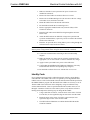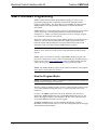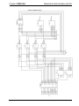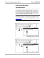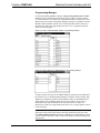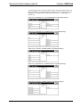
1
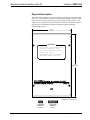
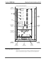
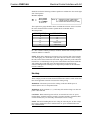
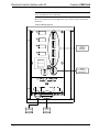
Crestron CNECI-4A Electrical Control Interface with AC Operations Guide This document was prepared and written by the Technical Documentation department at: Crestron Electronics, Inc. 15 Volvo Drive Rockleigh, NJ 07647 1-888-CRESTRON All brand names, product names, and trademarks are the property of their respective owners. ©1999 Crestron Electronics, Inc. Crestron CNECI-4A Electrical Control Interface with AC Contents Electrical Control Interface with AC: CNECI-4A 1 Description................................................................................................................................. 1 Functional Description ................................................................................................ 1 Physical Description.................................................................................................... 2 Leading Specifications............................................................................................................... 3 Setup .......................................................................................................................................... 4 Network Wiring........................................................................................................... 4 Hookup ........................................................................................................................ 5 Identity Code ............................................................................................................... 7 SIMPL Windows Programming ................................................................................................ 8 How the Program Works ............................................................................................. 8 How to Create the Program ....................................................................................... 10 Problem Solving ...................................................................................................................... 13 Troubleshooting......................................................................................................... 13 Further Inquiries ........................................................................................................ 13 Return and Warranty Policies .................................................................................................. 14 Merchandise Returns / Repair Service ...................................................................... 14 CRESTRON Limited Warranty................................................................................. 14 Operations Guide - DOC. 8149 Electrical Control Interface with AC: CNECI-4A • i Crestron CNECI-4A Electrical Control Interface with AC Electrical Control Interface with AC: CNECI-4A Description Functional Description The Electrical Control Interface with AC, CNECI-4A, is a wall-mounted interface for AC powered devices such as drapes, screens, and lifts. It is nearly identical to the CNECI-4 but the exception is that it draws operating power from an AC line that is independent of Cresnet system power. This allows for stand-alone operation prior to (and regardless of) connection to a Cresnet system. The CNECI-4A contains four single-pole, double-throw relays for Cresnet system power control. Using the SIMPL Windows program of the Cresnet system, the relays are programmed for basic operation or in any combination or sequence. Each of the relays has two common (COM) terminals (that are electrically connected), one normally-open (NO) contact, and one normally-closed (NC) contact. A signal from the Cresnet system (digital high) energizes the relay and a corresponding LED illuminates. The LOCAL INPUTS connector is a nine-pin connector, eight input pins and one ground. A closure from any input pin to ground provides an input to the Cresnet system. These input closures are programmed to control the relays and/or other control system function. The CNECI-4A operates from an AC power feed. The voltage is selectable from 100-125VAC or 220-250VAC. The CNECI-4A may be installed and operated in this mode via the LOCAL INPUTS by applying a momentary closure to ground to alternately latch and unlatch the corresponding relays. Upon establishing communication with the Cresnet system, the LOCAL INPUTS act as control inputs to the system. Through the NET connector, the +24V Cresnet system power serves as back-up power to energize the relays if the AC power is not available. If Cresnet system communications are not available while the +24V or the AC voltage is maintained, the relays may still be operated from LOCAL INPUTS pins 1 through 4. The closure to ground may be supplied from mechanical switches or Cresnet system I/O cards to operate the relays. Operations Guide - DOC. 8149 Electrical Control Interface with AC: CNECI-4A • 1 Electrical Control Interface with AC Crestron CNECI-4A Physical Description The CNECI-4A is housed in a gray, metal enclosure with silk-screened labels on the front cover. All connections are made to the internal PCB through enclosure conduit knock-outs that are located on the top, left-side, and bottom of the enclosure. Also supplied is one 4-position terminal block and one 9-position terminal block. Refer to the physical view and the PCB components diagrams after this paragraph: CNECI-4A Physical View 7.00 (17.78 cm) WARNING THIS COVER TO BE REMOVED BY QUALIFIED PERSONNEL ONLY. NO USER SERVICEABLE PARTS UNDER THIS COVER. NO BRANCH FUSES OR CIRCUIT BREAKERS INSIDE THIS UNIT. 11.00 (27.94 cm) CRESTRON Electronics, Inc. Rockleigh, N.J. 07647 ELECTRICAL CONTROL INTERFACE CNECI-4A DEPTH = 2.50" (6.35 cm) 4-POSITION TERMINAL BLOCK 2 • Electrical Control Interface with AC: CNECI-4A 9-POSITION TERMINAL BLOCK Operations Guide - DOC. 8149 Crestron CNECI-4A Electrical Control Interface with AC CNECI-4A Internal PCB Components 4 NO 4 PCB MOUNTING SCREWS (X6) COM COM 3 NC RELAY LEDs 3 NO COM 2 COM NC RELAY TERMINAL BLOCKS 1 2 NO COM COM AC FUSE NC 1 NO COM COM NC AC VOLTAGE SELECTOR SWITCH AC POWER TERMINAL BLOCK L L N G 115 230 CRESTRON LOW VOLTAGE SECTION DUST COVER NET L H 8 G ID CODE 7 6 3 1 2 Z G Y 24 5 LOCAL INPUTS NET 4 POWER MODEL: CNECI-4A POWER INDICATOR (AC or +24V) ID CODE (NET ID) INDICATOR CRESNET SYSTEM CONNECTOR LOCAL INPUTS CONNECTOR ID CODE (NET ID) SWITCHES Leading Specifications The table on the next page provides a summary of leading specifications for the CNECI-4A. Dimensions and weight are rounded to the nearest hundredth unit. Operations Guide - DOC. 8149 Electrical Control Interface with AC: CNECI-4A • 3 Electrical Control Interface with AC Crestron CNECI-4A Leading Specifications of the CNECI-4A SPECIFICATION Power Requirements DETAILS 24VDC, load factor of 5.0 watts, 100 -125VAC or 220 - 250VAC, 50 - 60Hz AC Fuse Type & Rating Slo-Blo, 5 x 20mm, glass; 250V, 160mA Relay Closure Rating 5A, 1/3HP @ 125 or 250VAC, 10A @ 30VDC Default Network ID 7F SIMPL Windows Version 1.30.01 or later1 with the addition of smwlib45.exe and smwlib45.txt CNX Operating System Version 5.01.09x or later CNX Monitor Version 2.00 or later Version 3.16.08 or later CNMS, CNRACK, CNLCOMP Operating System ST-CP Operating System Version 4.00.29 or later ST-CP Monitor Version 1.29 or later VisionTools Pro (VT Pro) Enclosure Version 1.2.0 or later 1, 2 Metal, gray semi-gloss Enclosure Conduit Knock-outs 3/4 in (1.91 cm) dia., five on three sides Dimensions & Weight Height: 11.00 in (27.94 cm) Width: 7.00 in (17.78 cm) Depth: 2.50 in (6.35 cm) Weight: 5.40 lb (2.40 kg) 1 The latest software versions can be obtained from the Software Downloads page (Simplwin and Touchpnl Libraries) of Crestron’s website (www.crestron.com). New users are required to register in order to obtain access to the FTP site. 2 VisionTools Pro is required only for SmarTouch programming. Otherwise, it is not needed. As of the date of manufacture, the CNECI-4A has been tested and found to comply with specifications for CE marking. NOTE: This device complies with part 15 of the FCC rules. Operation is subject to the following two conditions: (1) these devices may not cause harmful interference, and (2) these devices must accept any interference received, including interference that may cause undesired operation. Setup Network Wiring When calculating the wire gauge for a particular network run, the length of the run and the power factor of each network unit to be connected must be taken into consideration. If network units are to be daisy-chained on the run, the power factor of each network unit to be daisy-chained must be added together to determine the power factor of the entire chain. If the network unit is a home-run from a Crestron system power supply network port, the power factor of that network unit is the power factor of the entire run. The length of the run in feet and the power factor of the run 4 • Electrical Control Interface with AC: CNECI-4A Operations Guide - DOC. 8149 Crestron CNECI-4A Electrical Control Interface with AC should be used in the following resistance equation to calculate the value on the right side of the equation. Resistance Equation R < 40,000 L x PF Where: R = Resistance (refer to table below) L = Length of run (or chain) in feet PF = Power factor of entire run (or chain) The required wire gauge should be chosen such that the resistance value is less than the value calculated in the resistance equation. Refer to the table below: Wire Gauge Values RESISTANCE (R) WIRE GAUGE 4 16 6 18 10 20 15 22 13 Doubled CAT5 8.7 Tripled CAT5 NOTE: All network wiring must consist of two twisted-pairs. One twisted pair is the +24V conductor and the ground (G) conductor and the other twisted pair is the Y conductor and the Z conductor. NOTE: When daisy chaining network units, always twist the ends of the incoming wire and outgoing wire which share a pin on the network connector. After twisting the ends, tin the twisted connection with solder. Apply solder only to the ends of the twisted wires. Avoid tinning too far up or the tinned end becomes brittle and breaks. After tinning the twisted ends, insert the tinned connection into the network connector and tighten the retaining screw. Repeat the procedure for the other three network conductors. Hookup WARNING: Use extra caution when working with 100-125VAC or 220-250VAC. These voltages present an extreme hazard if inadvertent contact is made. Isolate and turn-off all applicable electrical circuits before routing wiring. WARNING: Disconnect power before working on this unit. While power is connected, there are live components inside. WARNING: Relay terminals 1, 2, 3, and 4 may still contain voltage even after AC power is disconnected. CAUTION: When connecting 100-125VAC or 220-250VAC to the AC power terminal block, terminal G must be ground, N is neutral, and the L terminals (either or both terminals, they are electrically connected) are for line voltage. NOTE: Instead of installing discrete AC wiring for each relay, the AC line voltage may be daisy-chained from the L terminal of the AC power terminal block to the relay COM terminals. Operations Guide - DOC. 8149 Electrical Control Interface with AC: CNECI-4A • 5 Electrical Control Interface with AC Crestron CNECI-4A NOTE: Review the Network Interconnection Diagram (latest revision of Doc. 5411) when making 4-wire connections. Refer to the diagram below and complete the steps on the next page to hookup the CNECI-4A: 4 CNECI-4A Hookup Diagram 4 NO COM COM 3 NC 3 NO COM 2 COM TO AC POWERED DEVICES NC 1 2 NO COM COM NC 1 NO COM COM NC L FROM 110-125VAC or 220-250VAC L N G 115 230 CRESTRON NET L H 8 G ID CODE 7 6 5 3 1 2 Z G Y 24 TO CRESNET SYSTEM LOCAL INPUTS NET 4 POWER MODEL: CNECI-4A FROM LOCAL INPUTS 6 • Electrical Control Interface with AC: CNECI-4A Operations Guide - DOC. 8149 Crestron CNECI-4A Electrical Control Interface with AC 1. Make sure that the Cresnet system and AC power circuits to be installed are turned off. 2. Remove the four CNECI-4A enclosure front cover screws. 3. Remove the six PCB mounting screws (do not remove the low voltage section dust cover) and remove the PCB. 4. Mount the CNECI-4A to the desired wall location. 5. Re-install the PCB with the six mounting screws. 6. Remove appropriate conduit knock-out(s) from the side(s) of the CNECI-4A enclosure. 7. Route the NET and LOCAL INPUTS wiring through the enclosure knock-out(s). 8. Attach the NET and LOCAL INPUTS wiring to the 4-position and 9-position terminal blocks, respectively, but do not connect the terminal blocks to the CNECI-4A. 9. Route the AC powered device wiring and AC power wiring through the enclosure knock-out(s) but do not connect. CAUTION: To prevent damage to the unit, do not connect the NET terminal block and AC power wiring until the other wiring has been connected or attached. 10. Connect the terminal blocks and wiring as shown in the hookup diagram. 11. Make sure that the AC voltage selector switch is positioned for the appropriate (115 for 110-125VAC or 230 for 220-250VAC) voltage. 12. Apply Cresnet system and/or AC power to the CNECI-4A. 13. Confirm that the POWER and NET indicators illuminate. (The relay LEDs illuminate when the corresponding relay energizes.) 14. Re-install the enclosure front cover with the four cover screws. Identity Code Every equipment and user interface within the network requires a unique identity code (NET ID or ID CODE). This code is recognized by a two-digit hexadecimal number from 03 to FE. The ID CODE of the unit must match an NET ID specified in the SIMPL Windows program. The ID CODE of the CNECI-4A is factory set to 7F. The ID CODE of the CNECI-4A can be changed by using two miniature rotary switches labeled H and L. These 16-position hexadecimal switches can be set to 0 through F. Attach the CNECI-4A to the control system (verify that the software is running) and complete the following steps to change the ID CODE: Operations Guide - DOC. 8149 1. Using a small flat screwdriver, rotate the arrow in the center of switch H to the first (or most significant) digit or letter of the new ID CODE. 2. Rotate the arrow in the center of switch L to the second (or least significant) digit or letter of the new ID CODE. 3. The NET indicator illuminates to confirm that the NET ID and ID CODE are identical. Electrical Control Interface with AC: CNECI-4A • 7 Electrical Control Interface with AC Crestron CNECI-4A SIMPL Windows Programming SIMPL (Symbol Intensive Master Programming Language) is an easy-to-use programming language that is completely integrated and compatible with all Crestron system hardware. The objects that are used in SIMPL are called symbols. SIMPL Windows offers drag and drop functionality in a familiar Windows® environment. SIMPL Windows is Crestron Electronics' software for programming Crestron control systems. It provides a well-designed graphical environment with a number of workspaces (i.e., windows) in which a programmer can select, configure, program, test, and monitor a Crestron control system. The next two subsections describe a sample SIMPL Windows program that utilizes a CNECI-4A. The first subsection details how the sample program works with a textual description and block diagram. The second subsection provides a broad description of how to actually create the SIMPL Windows program. NOTE: The following descriptions assume that the reader has knowledge of SIMPL Windows. If not, please refer to the extensive help information provided with the software. NOTE: There is no need to recreate this sample SIMPL Windows program. The program is available from Crestron’s Software Downloads page (Examples Library) of the Crestron website (www.crestron.com). Search for CNECI-4A.ZIP. This file contains the necessary files to recreate the following programming sample. NOTE: The SIMPL Windows program for the CNECI-4A identical to the program of the older Crestron product, the CNECI-4. How the Program Works NOTE: VisionTools Pro (VT Pro) is a Windows compatible software package for creating Crestron touchpanel screen designs. The basic CNECI-4A SIMPL program is shown as a block diagram on the next page. A CT-3000 touchpanel created with VT Pro, is used to control the relays of the CNECI-4A. For relay 1, the input1 signal on the clock of the TOGGLE causes the relay to change states. Relay1-on turns the relay on and relay1-off turns the relay off. The status of the toggle is fedback to the touchpanel. All four of the CNECI-4A relays are operated identically with their respective signals. The all-on and all-off signals, from the touchpanel through their respective BUFFERS, turn all four of the relays on or off. The AND symbols provide the toggle status feedback to the touchpanel. 8 • Electrical Control Interface with AC: CNECI-4A Operations Guide - DOC. 8149 Crestron CNECI-4A Electrical Control Interface with AC CNECI-4A SIMPL Program Operations Guide - DOC. 8149 Electrical Control Interface with AC: CNECI-4A • 9 Electrical Control Interface with AC Crestron CNECI-4A How to Create the Program Configuration Manager Use the Configuration Manager workspace (Project | Configure System) in SIMPL Windows to select and configure all the devices that need to be included into the system. For this example, from the Control Systems folder in the Device Library, select CNMSX-AV. From the Touchpanels (Wired) folder, drop and drag the CT-3000 symbol into System Views and set the NET ID to 03. Drag and drop the CNECI-4A (from Network Control Modules folder in the Device Library) into System Views. The NET ID of the CNECI-4A is set to 7F. NOTE: SIMPL Windows v1.30.01 or later is required to program the control system containing a CNECI-4A. If using an earlier version of SIMPL Windows, Crestron recommends a SIMPL Windows and operating system upgrade. The latest version can be obtained from the Software Downloads page of Crestron’s website (www.crestron.com). New users are required to register in order to obtain access to the FTP site. System View of the CT-3000 in SIMPL Windows’ Configuration Manage System View of the CNECI-4A in SIMPL Windows’ Configuration Manager 10 • Electrical Control Interface with AC: CNECI-4A Operations Guide - DOC. 8149 Crestron CNECI-4A Electrical Control Interface with AC Programming Manager Use the Programming Manager workspace (Project | Program System) in SIMPL Windows to select symbols and assign their respective signals. For this example, CT-3000 and CNECI-4A symbols were added automatically when the devices were added to the system in the Configuration Manager workspace. Expand the Network Modules folder and double click on the CT-3000 and CNECI-4A for detail views (alternatively CTRL+D or drag and drop into Detail View). Assign the signals as shown after this paragraph. Detail View of the CT-3000 in SIMPL Windows’ Programming Manager Detail View of the CNECI-4A in SIMPL Windows’ Programming Manager All logic symbols necessary for the SIMPL Windows program must be added from the Symbol Library in the Programming Manager workspace. In this example, drag and drop four TOGGLE symbols from the Memory folder, two BUFFER and two AND symbols from Conditional folder into the Logic folder in Program View. Expand the Logic folder and double click on symbol icons for a detail view (alternatively CTRL+D or drag and drop into Detail View). Assign signals as shown on the next pages. NOTE: For more descriptive symbol names, as shown in the illustrations above, right mouse click on the symbol icons in the Logic folder in Program View and select Edit Symbol Comment (alternatively, highlight the icon and depress Ctrl+R or Tab). Enter new descriptive names in the “Enter Symbol Comment” dialog boxes and click OK. Operations Guide - DOC. 8149 Electrical Control Interface with AC: CNECI-4A • 11 Electrical Control Interface with AC Crestron CNECI-4A To assign signals to the four toggle symbols, follow the example shown below. The signals shown below are toggle symbol S-1 signals for relay 1. Toggle symbols S-2 through S-4 are assigned similar signal names using relay2, 3, 4 and input2, 3, 4, respectively. Detail View of a TOGGLE (S-1 - S4) in SIMPL Windows’ Programming Manager Detail View of a BUFFER (S-5) in SIMPL Windows’ Programming Manager Detail View of a AND (S-6) in SIMPL Windows’ Programming Manager Detail View of a BUFFER (S-7) in SIMPL Windows’ Programming Manager Detail View of a AND (S-8) in SIMPL Windows’ Programming Manager 12 • Electrical Control Interface with AC: CNECI-4A Operations Guide - DOC. 8149 Crestron CNECI-4A Electrical Control Interface with AC Problem Solving Troubleshooting The table below provides corrective action for possible trouble situations of the CNECI-4A. If further assistance is required, please contact a Crestron customer service representative. WARNING: Disconnect power before working on this unit. While power is connected, there are live components inside. WARNING: Relay terminals 1, 2, 3, and 4 may still contain voltage even after AC power is disconnected. CNECI-4A Troubleshooting TROUBLE Green POWER indicator does not POSSIBLE CAUSE(S) CORRECTIVE ACTION CNECI-4A is not receiving Check AC fuse. If necessary, replace only with the AC power. same fuse type and rating. illuminate. USE CAUTION. Verify that AC wires into terminal block(s) are secure. CNECI-4A is not receiving Verify that cable plugged into NET connector is +24V power. secure. Yellow NET indicator does not Loose network connection. Verify that cable plugged into NET connector is secure. illuminate. Improper NET ID. Verify that the ID CODE of the CNECI-4A matches the Cresnet NET ID. Refer to "Identity Code". AC powered devices will not operate properly. AC voltage selector switch Confirm that AC selector switch is positioned to in wrong position. 115 or 230 as appropriate. Further Inquiries If you cannot locate specific information or have questions after reviewing this guide, please take advantage of Crestron's award winning customer service team by calling the Crestron corporate headquarters at 1-888-CRESTRON [1-888-273-7876]. For assistance in your local time zone, refer to the Crestron website (www.crestron.com) for a listing of Crestron worldwide offices. You can also log onto the online help section of the Crestron website (www.crestron.com) to ask questions about Crestron products. First-time users will need to establish a user account to fully benefit from all available features. Operations Guide - DOC. 8149 Electrical Control Interface with AC: CNECI-4A • 13 Electrical Control Interface with AC Crestron CNECI-4A Return and Warranty Policies Merchandise Returns / Repair Service 1. No merchandise may be returned for credit, exchange, or service without prior authorization from CRESTRON. To obtain warranty service for CRESTRON products, contact the factory and request an RMA (Return Merchandise Authorization) number. Enclose a note specifying the nature of the problem, name and phone number of contact person, RMA number, and return address. 2. Products may be returned for credit, exchange, or service with a CRESTRON Return Merchandise Authorization (RMA) number. Authorized returns must be shipped freight prepaid to CRESTRON, 6 Volvo Drive, Rockleigh, N.J., or its authorized subsidiaries, with RMA number clearly marked on the outside of all cartons. Shipments arriving freight collect or without an RMA number shall be subject to refusal. CRESTRON reserves the right in its sole and absolute discretion to charge a 15% restocking fee, plus shipping costs, on any products returned with an RMA. 3. Return freight charges following repair of items under warranty shall be paid by CRESTRON, shipping by standard ground carrier. In the event repairs are found to be non-warranty, return freight costs shall be paid by the purchaser. CRESTRON Limited Warranty CRESTRON ELECTRONICS, Inc. warrants its products to be free from manufacturing defects in materials and workmanship under normal use for a period of three (3) years from the date of purchase from CRESTRON, with the following exceptions: disk drives and any other moving or rotating mechanical parts, pan/tilt heads and power supplies are covered for a period of one (1) year; touchscreen display and overlay components are covered for 90 days; batteries and incandescent lamps are not covered. This warranty extends to products purchased directly from CRESTRON or an authorized CRESTRON dealer. Purchasers should inquire of the dealer regarding the nature and extent of the dealer's warranty, if any. CRESTRON shall not be liable to honor the terms of this warranty if the product has been used in any application other than that for which it was intended, or if it has been subjected to misuse, accidental damage, modification, or improper installation procedures. Furthermore, this warranty does not cover any product that has had the serial number altered, defaced, or removed. This warranty shall be the sole and exclusive remedy to the original purchaser. In no event shall CRESTRON be liable for incidental or consequential damages of any kind (property or economic damages inclusive) arising from the sale or use of this equipment. CRESTRON is not liable for any claim made by a third party or made by the purchaser for a third party. CRESTRON shall, at its option, repair or replace any product found defective, without charge for parts or labor. Repaired or replaced equipment and parts supplied under this warranty shall be covered only by the unexpired portion of the warranty. Except as expressly set forth in this warranty, CRESTRON makes no other warranties, expressed or implied, nor authorizes any other party to offer any warranty, including any implied warranties of merchantability or fitness for a particular purpose. Any implied warranties that may be imposed by law are limited to the terms of this limited warranty. This warranty statement supercedes all previous warranties. Trademark Information All brand names, product names, and trademarks are the sole property of their respective owners. Windows is a registered trademark of Microsoft Corporation. Windows95/98/Me/XP and WindowsNT/2000 are trademarks of Microsoft Corporation. 14 • Electrical Control Interface with AC: CNECI-4A Operations Guide - DOC. 8149 Crestron CNECI-4A Electrical Control Interface with AC This page intentionally left blank. Operations Guide - DOC. 8149 Electrical Control Interface with AC: CNECI-4A • 15 Crestron Electronics, Inc. 15 Volvo Drive Rockleigh, NJ 07647 Tel: 888.CRESTRON Fax: 201.767.7576 www.crestron.com Operations Guide – DOC. 8149 07.99 Specifications subject to change without notice.