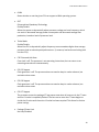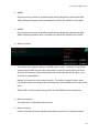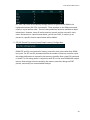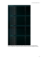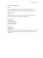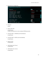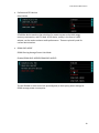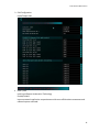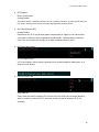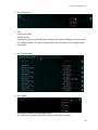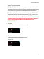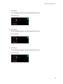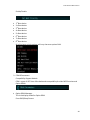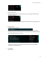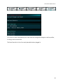
1
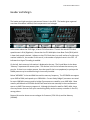
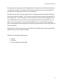
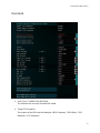
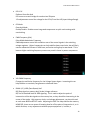
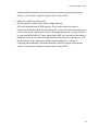
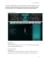
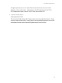
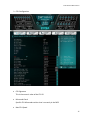
EVGA X79 Dark Motherboard Configuring the X79 Dark BIOS This supplementary manual explains the different menus and selections within the BIOS and provides a description of the different options enabling you to configure the X79 Dark BIOS for your needs. 1. 2. 3. 4. 5. 6. 7. Entering BIOS 2 Header and Margin Information 3 Overclock 6 Memory 22 Advanced 26 Boot 43 Save and Exit 48 1 EVGA X79 Dark Motherboard Enter the BIOS The X79 Dark features a UEFI BIOS, allowing for full mouse and keyboard support to streamline configuration. The BIOS enables you to use the base configuration of the motherboard to set preferences for features and configure the board to perform optimally. Follow the basic steps below to enter your BIOS. 1. Power on the computer 2. Press the Del / Delete key when the message “Press Del to enter BIOS” appears on screen. a. In some instances, the X79 Dark can complete the POST sequence before the video card fully initializes and prevent you from seeing the POST screen and the prompt for entering the BIOS, which may cause you to miss the opportunity to enter the BIOS. In these instances, please repeatedly press the Del/Delete button for a few seconds following the power on. The X79 Dark has 3 separate BIOS’s, toggled via the BIOS select switch. EVGA STRONGLY recommends that you leave at least one BIOS unmodified to ensure that you have a failsafe point that allows you to boot is an error occurs. 2 EVGA X79 Dark Motherboard Header and Margin The header and right margin are permanent fixtures in the BIOS. The header gives a general overview of hardware installed, basic temperatures and voltages. In the center above the EVGA logo, is basic CPU information. There is the overall CPU clock speed shown in GHz (Gigahertz). Above that the CPU Multiplier times Base Clock (BCLK) which is how clock speed is derived. Adjacent to the CPU Clock there is a small outline of a chip and a number inside of it, the number in this case 4, is the number of physical cores in the CPU. HT indicates that Hyper Threading is enabled. On the left, basic memory information is displayed at the top. The 8 small blue circles above “Memory” represents the memory slots. The number in the circle indicates the memory size per slot. If there is no number present, then that specific slot is not populated, or perhaps the DIMM present may be malfunctioning or incorrectly installed. Below “MEMORY” is the total RAM size and the memory frequency. The X79 DARK can support up to 64GB of RAM, and speeds up to 2400+MHz. Current Sandy Bridge-E processors are rated for up to 1600 MHz memory and Ivy bridge-E processors are rated for up to 1866 MHz. Most memory will default to 1333 MHz and this will need to be set manually to the manufacturers spec or to XMP if the memory supports it. Although this board is rated for 2400+ MHz, there are many factors that can limit your overclocking ability such as memory controller in the CPU, among others. Bottom left section shows current voltages for Processor (CPU VCore) and the Memory (VDIMM). 3 EVGA X79 Dark Motherboard The PCI-Express Breakdown is on the upper right. From the center out is the uppermost PCI-E slots to the lower slots. The lower row of blue circles will show what PCIe generation the slot is running at. The PCIe generation options are 1.0 2.0 and 3.0. The upper circles indicate the PCIe lane count for the corresponding slot. PCIe lane count options are 1, 4, 8, or 16. The VRM and CPU temperatures are located below the PCI-E information. These are the 2 most critical items on the motherboard requiring thermal monitoring. Keep in mind, however, that these temperatures are at idle and do not necessarily reflect the temperature you may see either in Windows or within an application under load. Temperatures are displayed in Celsius which is the industry standard. Below the header are the 5 buttons that will bring you to specific BIOS menus, and these will be covered in the sections below. The right Margin is the help legend, and gives a brief description of the current item you have selected. 4 EVGA X79 Dark Motherboard The upper portion will give you a brief explanation of a selected item. Below that are the basic commands for the BIOS. The modern UEFI (Unified Extensible Firmware Interface) BIOS GUI also allows for full navigation via mouse or the arrow keys. The lower portion of this section contains icons for saving screen shots of the BIOS and listing the current version of the BIOS. The F12 key can be used to save screen shots of the BIOS to a USB storage drive. To use this feature, a pre-formatted thumb drive must be plugged into one of the USB headers, then press F12 and a .bmp image will be saved to the thumb drives root folder. This may be used to easily share BIOS configurations, or to visually back up settings prior to doing a BIOS update to quickly and easily set original values back into the BIOS after the flash is completed. The BIOS version listed is the current version flashed of the ROM image, and will automatically update every time the new BIOS is flashed. Reference for the different bullet points: Setting Sub menu Preset Configurations (like XMP) 5 EVGA X79 Dark Motherboard Overclock Intel® Core™ i7-4820K CPU @3.70GHz This identifies the currently installed CPU model Target CPU Frequency The product of the BCLK and the Multiplier: (BCLK Frequency * BCLK Ratio) * CPU Multiplier = CPU Frequency. 6 EVGA X79 Dark Motherboard Current PCI-E Frequency Current set PCI-E Frequency (100 MHz default), PCI-E speed is generated by BCLK divided by BCLK ratio. If PCI-E Frequency is outside of 5% margin, peripheral devices may have issues and, when pushed high enough, can cause the board not to POST. Internal PLL (Phased Locked Loop) Override Enable/Disable Enhanced clock management for extreme overclocking. Typically only used to stabilize very high CPU Overclocks. S3 resume may not work properly, if this is enabled CPU Multiplier Control The three modes for controlling the CPU multiplier. The 3 options - Auto, Manual and ELEET Ratio Control - all will affect the CPU Multiplier Settings Menu(s) below. Manual mode forces ratio to remain constant during any conditions, while ELEET Ratio Control mode will allow using software adjustment during runtime (such as ELEET X Tuning utility or Intel XTU). CPU Multiplier Setting In manual mode you can select each core’s multiplier separately. In ELEET Ratio Control, you can only control the overall CPU Multiplier Setting across all available cores. When core 1 ratio is changed, all cores will reflect this number. A core ratio limit may be LOWERED below the ratio limit of the core number directly above it. However, if a 7 EVGA X79 Dark Motherboard core ratio limit is increased above the ratio limit of the core number above it in the list, it will adjust all cores. All multiplier settings can be left at auto. CPU Multiplier has a range of 12 to 63. BCLK Frequency Ratio Base Clock Frequency Ratio is the multiplier for the Base Clock Frequency Setting, and this is one component of the Target CPU Frequency. Ensure correct memory frequency after adjustment BCLK Ratio, as memory clock is affected by this ratio same way, as CPU. BCLK Frequency Setting This is the initial frequency set to the CPU’s Base Clock and is one component in the Target CPU Frequency. The BCLK Frequency range is 85 Mhz-250 Mhz, depending on BCLK ratio. Adjusting BCLK may not be an ideal way to overclock the system, as it affects all subsystems, like memory, PCI-E, peripherals, however in short order you may start seeing drastic stability issues. Safe margin usually lies within 3% for SandyBridge-E generation CPUs, and around 5-7% for IvyBridge-E generation CPUs. 8 EVGA X79 Dark Motherboard K-Boost K-Boost has the option of Enable/Disable This is a CPU voltage tweak at POST. This will help with overclocking on Ivy-Bridge-E CPUs. Leaving it disabled will use the Intel reference spec for power delivery on POST. VCore Mode Fixed Mode / Offset Mode Fixed mode sets the Vcore to a static value. Offset adds an increased voltage threshold above factory Vcore, the upper limit of the offset is defined in the BIOS. The CPU will dynamically draw additional voltage as needed. Offset is useful to increase overclocking margin under heavy stress, while keeping temperatures lower under low-medium load. Vcore Voltage This is the voltage set in the BIOS for the CPU. Changing this number can assist with system stability during overclocking. There is no fixed default value as different CPUs/CPU Batches run at different voltages out of the box. Also, the VCore can fluctuate as part of the normal function of the CPU/Motherboard, as power consumption is dynamic. This is expected and normal. VCore default setting is Auto. To change the voltage, select a target voltage from the pulldown menu, or click on the field and enter the desired voltage value on the 10 Key pad, and press “Enter”. CHANGE VCORE AT YOUR OWN RISK LEVELS OUTSIDE SPEC CAN VOID CPU WARRANTY. In Fixed mode, just enter the desired target CPU VCore. In offset mode, enter the amount of additional voltage desired for the VCore to use as needed. VCore VDroop Voltage Droop for the CPU VCore. Voltage droop is the loss in output voltage from a device as it drives a higher load. Employing droop in a voltage regulation circuit increases the headroom for load transients. Allowing VDroop reduces power consumption by VRM and CPU. This in turn reduces wear on the CPU and heat generated. 9 EVGA X79 Dark Motherboard However, for moderate to extreme overclocking it may be necessary to reduce/disable this feature to assist with stability, to keep provided voltage constant, even at cost of higher power consumption. OCP Setting Over Current Protection Setting (for CPU VCore) This may be changed to the various options listed below, this is a hard shut off protection level for the CPU Vcore rail. If your CPU pulls above the preset level, it will trip the OCP and shut off in the same manner as a PSU when its OCP is tripped. DIMM (1-4) Voltage Double In-line Memory Module This setting controls the voltage for the memory modules installed in slots 1-4. Auto will adjust voltage depending on memory frequency, or the values may be entered manually or scroll through the options with the +/- keys. DIMM (5-8) Voltage Double In-line Memory Module This setting controls the voltage for the memory modules installed in slots 1-4. Auto will adjust voltage depending on memory frequency, or the values may be entered manually or scroll through the options with the +/- keys. 10 EVGA X79 Dark Motherboard VSA Voltage Voltage System Agent Voltage VSA Voltage adjusts the CPU Integrated memory controller (IMC) and system control unit (SCU) voltage. High memory overclocks or BCLK overclocking may need increasing of this voltage. Auto will adjust voltage depending on memory frequency, or the values may be entered manually or scroll through the options with the +/- keys.. VSA VDroop Voltage System Agent Voltage Droop Allows for a reduction in VSA voltage based off of Intel specs. This can also be disabled. VCCIO Voltage Voltage at a Common Connector Input/Output terminals This is the I/O voltage for high-speed CPU Interfaces. Auto will attempt to detect proper voltage for the memory controller, or the values may be entered manually or selected by scrolling through the options with the +/- keys. In most cases, this only needs to be adjusted when doing heavy overclocking and/or very high speed RAM usually 2133 MHz and higher. VPLL Voltage Phase Lock Loop Domain Voltage A phase lock loop (PLL) is a control system that generates an output clock signal whose phase is locked on the input signal. This power domain used for CPU internal clocking units, and adjusting voltage may help with overclocking. PCH 1.1V Platform Controller Hub PCH serves as a south bridge for modern Intel Chipsets 1.1v is the base voltage core for the PCH core domain. 11 EVGA X79 Dark Motherboard PCH 1.5V Platform Controller Hub PCH serves as a south bridge for modern Intel Chipsets 1.5v adjustments control the voltage for the PCH I/O and the IVR (Input Voltage Range). OC Mode Overclock Mode Enable/Disable. Disables some integrated components to quick assist settings with overclocking. PWM Frequency (KHz) Pulse Width Modulation Frequency PWM adjustments control the oscillation rate of the control signals in the switching voltage regulator. Higher frequencies can help stabilize heavy overclocks, but will likely cause a substantial increase in VRM heat, and active cooling may be warranted. This is because higher switching frequency cause more parasitic losses in power components. VSA PWM Frequency Changes the oscillation frequency for the Voltage System Agent. Increasing this can help stabilize an overclock, but generates substantial heat. DIMM 1,2,3,4 DQ (Data Queue) Vref DQ (Data signal on memory bus) Strobe Voltage reference DQ Vref is threshold level for DDR signaling. This is used to adjust the point of intersection of the data signals on the memory bus, as they should be intersecting in the center of the strobe. High memory clocks, and voltage adjustments, can skew this and as such cause BSOD and POST issues. Adjusting the VREF can help stabilize the memory. HOWEVER, there are no means of knowing how far off the point of intersection is, or in which direction, so any adjustments without proper equipment is, in effect, a 12 EVGA X79 Dark Motherboard completely blind adjustment and should be done in small increments using extreme caution, as it may result in data corruption and/or a lack of POST. DIMM 5,6,7,8 DQ (Data Queue) Vref DQ (Data signal on memory bus) Strobe Voltage reference DQ Vref is threshold level for DDR signaling. This is used to adjust the point of intersection of the data signals on the memory bus, as they should be intersecting in the center of the strobe. High memory clocks, and voltage adjustments, can skew this and as such cause BSOD and POST issues. Adjusting the VREF can help stabilize the memory. HOWEVER, there are no means of knowing how far off the point of intersection is, or in which direction, so any adjustments without proper equipment is, in effect, a completely blind adjustment and should be done in small increments using extreme caution, as it may result in data corruption and/or a lack of POST. 13 EVGA X79 Dark Motherboard The options in the XTECH Menu are not normally used for most system configurations. These are typically reserved for stabilizing extreme overclocks (sub zero). Because these settings are for hyper specific uses, if used inappropriately, may render the board unbootable. XTECH Configuration MCU Version Microcontroller Unit MCU is an IC that manages system operation. The revision will be periodically updated with the motherboard BIOS, if needed. Firmware Auto Update Enable/Disable This is a firmware for the MCU integrated into the BIOS, so if it differs from the one flashed on the motherboard, it will auto update during post. During this one-time 14 EVGA X79 Dark Motherboard operation system may post longer than usual. Do not power off or reset system during this phase, or firmware corruption may occur. PCI-E Compensation Signal On/Off At high frequencies you can see phase distortion and loss issues, this can result in distortion at the receiver input. Frequently seen in PCI-E frequencies above 5 GHz for GEN2. PCI-E is specific to PCI-E lanes derived from the PCH. DMI (Direct Media Interface) Compensation Signal On/Off The DMI is the interconnect between the Intel Processor and the PCH (Platform Controller Hub). The high frequencies present in overclocking (especially in extreme overclocking) can cause signal stability and frequency oscillation, DMI compensation can help stabilize this byproduct of overclocking. DMI BIAS level On/Off BIASing is the application of DC voltages used to setup a fixed level of current. In this case BIAS is DC voltage directly applied between two points (CPU and PCH) for the purpose of controlling a circuit, applying DC BIAS will also yield a reduction of capacitance. BIAS can direct the amount of current going to other components in a circuit through transistor amplification, to help avoid and/or correct signal distortion. The DMI is one component between the CPU and the PCH. PCI-E BIAS Level On/Off BIASing is the application of DC voltages used to setup a fixed level of current. In this case BIAS is DC voltage directly applied to the SCU (Storage Control Unit) Link for the purpose of controlling a circuit, applying DC BIAS will also yield a reduction of capacitance. BIAS can direct the amount of current going to other components in a circuit through transistor amplification, to help avoid and/or correct signal distortion. The SCU Uplink is another device between the CPU and PCH, and this controls the 4 PCIE lanes that are pulled and used for storage controllers. This will help prevent storage controller errors/instability under EXTREME overclocks. PEG (PCI Express Graphics) Compensation Signal On/Off 15 EVGA X79 Dark Motherboard At high frequencies you can see phase distortion and loss issues, this can result in distortion at the receiver input. Frequently seen in PCI-E frequencies above 5 GHz. PEG Compensation Signal is specific to PCI-E lanes derived from CPU. +12V PCI-E Power Source 24pin power/6 pin PCI-E This is used to enable the 6pin PCI-E power jack on the lower edge of the board. This is primarily used to allow cards in 3-way/4-way SLI to draw additional power from the PSU and balance the load, rather than pull all power directly from the 24 pin. 16 EVGA X79 Dark Motherboard CPU Configuration CPU Signature This is the numeric value of the CPU ID Microcode Patch Specific CPU Microcode revision that is currently in the BIOS Max CPU Speed 17 EVGA X79 Dark Motherboard This shows the max speed of the CPU accounting for any present overclocks, but does not account for clocks adjusted via Turbo. Max CPU Speed = (CPU Multiplier X (BCLK Frequency Setting X BCLK Frequency Ratio)). For example, a i7 4820 has a base multiplier of 37, a BCLK of 100 (as all do out of the box). (37 X (100 X 1.0))=3.7GHz. Min CPU Speed This shows the current minimum CPU speed when the CPU is throttled. (CPU Base Multiplier X (BCLK Frequency Setting X BCLK Frequency Ratio)). Most socket 2011 CPU’s have a 12 as the lowest available multiplier. Intel VT-x Technology Vanderpool Technology, which is the Intel code/project name for “Intel Virtualization Technology”. L1 Data Cache Level 1 cache is to improve data access speed in cases when the CPU accesses the same data multiple times. Shows the amount of cache for this level which is installed (hardwired) within the CPU. L1 Code Cache Data that's stored in the instruction cache is generally somewhat different than what's stored in the data cache -- along with the instructions themselves, there are annotations for things like where the next instruction starts, to help out the decoders. Some processors (E.g., Netburst, some SPARCs) use a "trace cache", which stores the result of decoding an instruction rather than storing the original instruction in its encoded form. Shows the amount of cache for this level which is installed (hardwired) within the CPU. L2 Data Cache Level 2 cache is to reduce data access time in cases where the same data was already accessed before. Shows the amount of cache for this level which is installed (hardwired) within the CPU. L3 Data Cache Unified Cache shared by all cores Shows the amount of cache for this level which is installed (hardwired) within the CPU. 18 EVGA X79 Dark Motherboard 64 Bit States whether or not the given CPU can support a 64bit operating system. EIST Enhanced Intel Speedstep Technology Enable/Disable Allows the system to dynamically adjust processor voltage and core frequency, which can result in decreased average power consumption and decreased average heat production, based on level of processor load. Turbo Mode Enable/Disable Allows the CPU to dynamically adjust frequency to accommodate higher than average processor load to maintain peak performance. (In essence, low level overclocking built into the CPU). C1E Enhanced Halt State Core clock is off. The processor is not executing instructions, but can return to an executing state almost instantaneously. CPU C3 Support Clock generator is off. The processor does not need to keep its cache coherent, but maintains other states. CPU C6 Support Clock generator is off. The processor does not need to keep its cache coherent, but maintains other states. CPU C7 Support The processor enters the package C7 low power state when all cores are in the C7 state and the L3 cache is completely flushed. The last core to enter the C7 state begins to shrink the L3 cache until the entire L3 cache has been emptied. This allows for further power savings. Package C State Limit No Limit/Disabled 19 EVGA X79 Dark Motherboard TDC Limit Thermal Design Current Long Duration Power Limit Defines the throttle point for the first layer of CPU power protection. This is a wattage value set to equal the TDP of the processor by default. This can be adjusted to accommodate extreme overclocks, typically this does not need to be altered. Short Duration power Limit Define the second throttle point for the processor, this is also a wattage value that is by default set to 1.25 times the TDP, and is a value that according to Intel spec only has to be sustainable for 10ms. This is a PEAK AND NON-SUSTAINABLE POWER LIMIT. As with Long Duration, this can be adjusted for extreme overclocks, it is recommended that the ratio of 1.25 times the Long Duration Power Limit is maintained regardless of overclocking and adjusted values. Hyper Threading Technology Hyper threading is processor core virtualization and functions as additional processing cores for some applications. This is also why a hex core processor shows up as 12 threads in Windows. Active Processor Cores This setting allows the selection of the number of processor cores to enable and make available for use. Limit CPUID Maximum When enabled, this sets the CPUID value to 03h, which assists with using Hyper threaded CPUs in older operating systems that do not natively support Hyper Threading. Execute Disable Bit Hardware-based security feature for protection against malicious software. Hardware Prefetcher The hardware prefetcher operates transparently, without programmer intervention, to fetch streams of data and instruction from memory into the unified second-level cache. The prefetcher is capable of handling multiple streams in either the forward or backward direction. It is triggered when successive cache misses occur in the last-level cache and a stride in the access pattern is detected, such as in the case of loop iterations that access array elements. 20 EVGA X79 Dark Motherboard Adjacent Cache Line Prefetch The Adjacent Cache-Line Prefetch mechanism, like automatic hardware prefetch, operates without programmer intervention. When enabled through the BIOS, two 64-byte cache lines are fetched into a 128-byte sector, regardless of whether the additional cache line has been requested or not. In applications with relatively poor spatial locality, the cache miss ratio is higher. DCU Streamer Prefetcher Data Cache Unit Prefetching for L1 cache DCU IP Prefetcher The IP prefetcher scrutinizes historical reading in order to have an overall diagram and loads "foreseeable" data in L1 cache. Each core also has one. Intel Virtualization Technology Hardware based virtualization built into the CPU, used in conjunction with virtualization software to create multiple virtual environments/ virtual PC’s within a single PC. BCLK 125 MHz Quick Setting Applies a 1.25 multiplier to the BCLK, as well as does some base voltage adjustments to help stabilize. PCIe clock kept at stock 100 MHz with this setting. BCLK 133 MHz Quick Setting Applies a 1.25 multiplier to the BCLK and raised BCLK to 133 MHz, as well as does some base voltage adjustments to help stabilize. PCIe clock will be 106.4 MHz with this setting. BCLK 145 MHz Quick Setting Applies a 1.66 multiplier to the BCLK and reduces BCLK to 145 MHz, as well as does some base voltage adjustments to help stabilize. PCIe clock will be 87.3 MHz with this setting. BCLK 166 MHz Quick Setting Applies a 1.66 multiplier to the BCLK, as well as does some base voltage adjustments to help stabilize. PCIe clock will be 100 MHz with this setting. 21 EVGA X79 Dark Motherboard Memory Target Memory Frequency Displays the speed of the RAM. 22 EVGA X79 Dark Motherboard XMP#1 Extreme memory profiles are predetermined settings designed to optimize the RAM. XMP1 will display based on what is available for a specific kit of RAM on this profile. XMP#2 Extreme memory profiles are predetermined settings designed to optimize the RAM. XMP2 will display based on what is available for a specific kit of RAM on this profile. Memory Profiles The options are Automatic, Manual, and XMP Profile 1 and 2. Automatic is the default speed set by the BIOS to ensure the system boots initially so correct values can be set. Typically the frequency will be below advertised, and the latency will be higher, this is for universal compatibility. Manual is the option to enter values manually. This option is typically chosen when running fast memory kits and/or heavy clocking and recommended only for experienced users. XMP Profile 1 and 2 are preset settings built into the RAM from the manufacturer. Memory Frequency This shows the current speed of the memory. Memory Latency Latency is shown and can be adjusted when Memory Profiles is set to Manual mode. 23 EVGA X79 Dark Motherboard tCL, tRCD, tRP, tRAS are the latency settings listed on a typical stick of RAM in the hyphenated section (9-9-9-24, for example). Those numbers on the RAM are entered, usually in top to bottom order. There are many additional latencies available to adjust below these. However, these all involve memory controls and are not used in most cases. Because this is a quad channel board, you will see CH0-3; if memory is not present in a specific channel related values will be hidden. RTL/IOL (Round Trip Latency/Input/Output Latency) Configuration DRAM RTL and IOL are measured in memory controller clock cycles rather than DRAM bus cycles. The RTL and IOL parameters define the number of memory controller cycles that elapse before data is returned to the memory controller after a read CAS command is issued. The IOL setting works in conjunction with RTL to fine tune DRAM buffer output latency. Both settings are auto-sensed by the memory controller during the POST process, and usually not recommended to adjust. 24 EVGA X79 Dark Motherboard Manual adjustment should not be necessary unless the system is running speeds in excess of 2400 MHz or higher BCLKs where some drift may cause read/write leveling. 25 EVGA X79 Dark Motherboard Silent Mode Enable/Disable This option toggles the Internal PC Speaker on or off. ACPI Settings Advanced Configuration and Power Interface 26 EVGA X79 Dark Motherboard Enable ACPI Auto Configuration On/Off Enables ACPI based power saving functions. Enabling or disabling ACPI Auto Configuration AFTER an OS has been installed may well render the OS unbootable. Enable Hibernation On/Off This references S4 type sleep state, where all information in the RAM is written to nonvolatile memory such as a Hard Drive and powered down. ACPI Sleep States Suspend Disabled S1 Only (CPU Stop Clock) S3 Only (Suspend to RAM) Both S1 and S3 available EUP Control Energy Using Product Enable/Disable This is a standard primarily used in Europe for systems in a power off state, and controls the wattage able to be consumed in a power off state, as it needs to be less than or equal to 1W. 27 EVGA X79 Dark Motherboard Onboard Device Configuration Bluetooth On/Off Marvell SATA RAID Enable/Disable Enables the RAID function on the secondary SATA3/6g controller PCI Express LAN 1 – 82579LM (Local Area Network) Enable/Disable PCI Express LAN 2 – 82574L (Local Area Network) Enable/Disable Marvell e-SATA Enable/Disable USB 3.0 (Rear Port 0, Port 1) Enable/Disable USB 3.0 (Rear Port 2, Port 3) Enable/Disable 28 EVGA X79 Dark Motherboard USB 3.0 (Header Port 4, Port 5) Enable/Disable EVGauge Support On/Off Azalia HD Audio On/Off Azalia Internal HDMI codec Enable/Disable North Bridge Compatibility RID Enable/Disable DRAM RAPL BWLIMIT DRAM Running Average Power Limit Bandwidth Limit This is a limiter for average power consumption for the DRAM module. (1 is the recommended Intel Value). 29 EVGA X79 Dark Motherboard Perfmon and DFX devices Hide/Unhide A PerfMon device monitors the activities of a remote system such as disk usage, memory consumption, and CPU load. A DFX device, usually in the form of a USB adaptor, can be used to enhance audio performance. These are primarily used for remote administration. DRAM RAPL MODE DRAM Running Average Power Limit Mode Disable/DRAM RAPL MODE0/DRAM RAPL MODE1 This will Disable or select one of the preconfigured (to Intel specs) power settings for DRAM average power consumption. 30 EVGA X79 Dark Motherboard IOH Configuration Input/Output Hub Intel® I/OAT Intel Input/Output Acceleration Technology Enable/Disable Improve network application responsiveness with more efficient data movement and reduced system overhead. 31 EVGA X79 Dark Motherboard DCA Support Direct Cache Access Enable/Disable This feature allows a capable I/O device, such as a network controller, to place data directly into CPU cache, reducing cache misses and improving application response times. Gen3 Equalization WA’s Enable/Disable Equalization for PCI-E may also be used to compensate for ripples in the channel that occur due to reflections from impedance discontinuities. Workarounds are need for early CPUs, but usually this setting can be kept on default state for retail. No Snoop Optimization VC1 or VC0/VCP/VC1 VC1 is Intel default, other setting is generally only recommended for debug uses, as it tends to cause latency. CPU PCI-E Port C x8 Auto/x4x4/x8 Either allow the board to allocate PCI-E lanes to the PCI-E-16x slots manually based on what is installed, or allocate PCI-E resources to the slot and its above 4x PCI-E slot manually. 32 EVGA X79 Dark Motherboard PORT 1A (Slot PE6) speed Allows the manual selection of which PCI-E Gen the slot is using, although it should auto-detect based off of the device plugged in. PORT 1A (Slot PE5) speed Allows the manual selection of which PCI-E Gen the slot is using, although it should auto-detect based off of the device plugged in. CPU PCI-E Port A x16 Allows the forced allocation of PCI-E lanes. Keep in mind this will not allow you to successfully force a lane allocation that is not possible. PORT 2C (Slot PE1) speed Allows the manual selection of which PCI-E Gen the slot is using, although it should auto-detect based off of the device plugged in. 33 EVGA X79 Dark Motherboard PORT 2A (Slot PE2) speed Allows the manual selection of which PCI-E Gen the slot is using, although it should auto-detect based off of the device plugged in. CPU PCI-E Port B X16 Allows the forced allocation of PCI-E lanes. Keep in mind this will not allow you to successfully force a lane allocation that is not possible. PORT 3C (Slot PE4) speed Allows the manual selection of which PCI-E Gen the slot is using, although it should auto-detect based off of the device plugged in. PORT 3A (Slot PE3) speed Allows the manual selection of which PCI-E Gen the slot is using, although it should auto-detect based off of the device plugged in. 34 EVGA X79 Dark Motherboard PORT 1A Enable/Disable PORT 1B Enable/Disable PORT 2A Enable/Disable PORT 2B Enable/Disable PORT 2C Enable/Disable PORT 2D Enable/Disable PORT 3A Enable/Disable PORT 3B Enable/Disable PORT 3C Enable/Disable PORT 3D Enable/Disable 35 EVGA X79 Dark Motherboard QPI Configuration ISOC Isochronous Mode Enable/Disable Enabling the Iscochronous Mode option reduces the credits available for memory traffic. For memory requests, this option reduces latency at the expense of throughput under heavy loads. SATA Configuration SATA Mode Disabled/IDE Mode/AHCI Mode/RAID Mode This shows the selectable mode options for the Intel SATA controller. 36 EVGA X79 Dark Motherboard Disabled – Turns off the controller IDE Mode – Runs the controller in IDE Emulated legacy mode. Only needed for certain OLD SATA devices or for compatibility purposes. AHCI Mode – Advanced Host Controller Interface, this allows for more modern functions of the controller such as NCQ (Native Command Queueing) and is also needed for proper function of an SSD. RAID Mode – Redundant Array of Inexpensive Drives, this opens the RAID (0/1/10/5) functions on the controller. RAID offers the same functions as AHCI. In general, this is the safest option, as it will support most legacy features and all AHCI features. ***DO NOT CHANGE THE SATA MODE AFTER YOU HAVE INSTALLED THE OPERATING SYSTEM, IT WILL BE RENDERED UNBOOTABLE, UNLESS PROPER DRIVER IS PREINSTALLED FIRST*** SATA Port0 This will display the device currently attached to this port Port 0 Hot Plug SATA Port1 This will display the device currently attached to this port Port 1 Hot Plug 37 EVGA X79 Dark Motherboard SATA Port2 This will display the device currently attached to this port Port 2 Hot Plug SATA Port3 This will display the device currently attached to this port Port 3 Hot Plug SATA Port4 This will display the device currently attached to this port Port 4 Hot Plug 38 EVGA X79 Dark Motherboard SATA Port5 This will display the device currently attached to this port Port 5 Hot Plug USB Configuration USB Devices: This is the list of what all is currently attached to the USB controllers USB Beep Enable/Disable USB Port0 Enable/Disable 39 EVGA X79 Dark Motherboard USB Port1 Enable/Disable USB Port2 Enable/Disable USB Port3 Enable/Disable USB Port4 Enable/Disable USB Port5 Enable/Disable USB Port6 Enable/Disable USB Port7 Enable/Disable USB Port8 Enable/Disable USB Port9 Enable/Disable USB Mass Storage Driver Support Enable/Disable USB Transfer Time-out 1sec/5sec/10sec/20sec 40 EVGA X79 Dark Motherboard Time delay after plugging in a USB device before a time-out occurs Device Reset time-out 10sec/20sec/30sec/40sec Device Power-up delay Auto/Manual Mass Storage Devices This will display any thumb drives, optical devices, external USB HDD’s, etc below that are currently attached to the system. H/W Monitor 41 EVGA X79 Dark Motherboard System Temperature JCPU_FAN1 JCHA_FAN JSYS1_FAN JSYS2_FAN JSYS3_FAN JAUX_FAN1 Values are live voltages taken from internal monitoring components. Most values will vary, this is normal, and also be different in Windows and under load. 42 EVGA X79 Dark Motherboard System Date System Time Admin Password User Password Bootup NumLock State On/Off Enables/Disables the keyboard number lock (for 10 key pad) status at POST Quiet Boot On/Off Fast Boot 43 EVGA X79 Dark Motherboard Enable/Disable 1st Boot device 2nd Boot device 3rd Boot device 4th Boot device 5th Boot device 6th Boot device 7th Boot device 8th Boot device All of the boot priority options will carry the same options field. CSM16 Parameters Compatibility Support Module CSM is a part of UEFI that offers backwards compatibility for older BIOS functions and Option ROMs. Option ROM Messages This is the display mode for Option ROM Force BIOS/Keep Current 44 EVGA X79 Dark Motherboard INIT19 Trap Response INIT19 is the decimal value for interrupt 0x13, which controls option ROM interface. Immediate/Postponed Immediate will launch this function during post, postponed will be during Legacy Boot. CSM Parameters Compatibility Support Module CSM translates the information generated under the EFI environment into the information required by the legacy environment and makes the legacy BIOS services available for booting to the operating system and for use in runtime. Storage option ROM need to be enabled to allow usage of external storage/RAID controllers, such as PCIe SAS cards. Launch CSM Enable/Disable 45 EVGA X79 Dark Motherboard Boot Option Filter Launch PXE OpROM Policy Launch Storage OpROM policy Launch Video OpROM policy Other PCI device ROM priority 46 EVGA X79 Dark Motherboard Hard Disk Drive BBS Priorities 1st Boot Device This will show all bootable HDDs/SSDs present. USB Key Drive BBS Priorities 1st Boot Device This will show all bootable USB Key devices UEFI Boot Drive BBS Priorities 1st Boot Device This will show all bootable UEFI drives 47 EVGA X79 Dark Motherboard This screen is more informational, this is the menu for saving BIOS changes as well as profiles, for things such as overclocks. The Boot Override is a list of currently bootable devices plugged in. 48