1
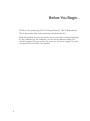
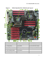
User Guide EVGA Classified Super Record 2 (SR-2) Dual Xeon Motherboard 2 EVGA Classified SR-2 Motherboard Table of Contents Before You Begin… ............................................................................................... 8 Parts NOT in the Kit ........................................................................................... 9 Intentions of the Kit .......................................................................................... 9 EVGA Classified Super Record 2 (SR-2) Motherboard ............................................ 10 Motherboard Specifications .............................................................................. 10 Unpacking and Parts Descriptions ....................................................................... 12 Unpacking....................................................................................................... 12 Equipment ...................................................................................................... 12 EVGA Classified SR-2 Motherboard ................................................................... 14 Hardware Installation .......................................................................................... 18 Safety Instructions .......................................................................................... 18 Preparing the Motherboard .............................................................................. 19 Installing the CPU ........................................................................................ 19 Installing the CPU Fan.................................................................................. 20 Installing DIMMs .......................................................................................... 21 Installing the Motherboard ............................................................................... 22 Installing the I/O Shield ............................................................................... 22 Securing the Motherboard into the Chassis .................................................... 23 Connecting Cables and Setting Switches ........................................................... 24 Power Connections ...................................................................................... 24 24-pin ATX Power (PW1) .......................................................................... 24 8-pin ATX 12V Power (PW12-P0-1, PW12-P1-1) ......................................... 25 3 Connecting IDE Hard Disk Drives .................................................................. 26 Connecting Serial ATA Cables ....................................................................... 27 Connecting Internal Headers ........................................................................ 28 Front Panel Header .................................................................................. 28 USB Headers ........................................................................................... 29 Audio Header ........................................................................................... 30 Fan Connections .......................................................................................... 31 Expansion Slots ........................................................................................... 32 PCI-E x16 Slots ........................................................................................ 33 Onboard Buttons ............................................................................................. 35 Clear CMOS Button .................................................................................. 35 RESET and POWER Button…………………………………………………………………….35 Post Port Debug LED and LED Status Indicators ................................................ 36 Post Port Debug LED ................................................................................ 36 LED Status Indicators ............................................................................... 36 Jumper Settings .............................................................................................. 37 PCI-E Disable Jumper ............................................................................... 37 Voltage Measure Point ..................................................................................... 38 EVGA Control Panel (ECP) ................................................................................ 39 Configuring the BIOS .......................................................................................... 47 Enter BIOS Setup ............................................................................................ 48 Main Menu ...................................................................................................... 49 Standard BIOS FeaturesMenu……………………………………………………………………….51 System Time/SystemDate…………………………………………………………………………52 Advanced BIOS Features ................................................................................. 53 SATA Configuration…………………………………………………………………………………..54 AHCI Configuration…………………………………………………………………………………..54 4 EVGA Classified SR-2 Motherboard E-SATA Controller (Back panel)………………………………………………………………….54 SATA Configuration………………………………………………………………………………………….55 Advanced Chipset Features………………………………………………………………………………56 USB Configuration……………………………………………………………………………………56 PCI-E Configuration………………………………………………………………………………….56 PCI/PNP Resource Management……………………………………………………………………….58 Clear NVRAM…………………………………………………………………………………………..58 Plug & Play O/S……………………………………………………………………………………….58 PCI Latency Timer……………………………………………………………………………………58 Allocate IRQ to PCI VGA……………………………………………………………………………59 Pallette Snooping……………………………………………………………………………………..59 PCI IDE Busmaster…………………………………………………………………………………..59 Offboard PCI/ISA IDE Card……………………………………………………………………….59 Boot Configuration Features…………………………………………………………………………60 Boot Settings Configuration………………………………………………………………………60 Boot Device Priority………………………………………………………………………………….60 Hard Disk Drives………………………………………………………………………………………60 Power Management Features……………………………………………………………………….61 ACPI Configuration…………………………………………………………………………………..61 Hardware Health Configuration…………………………………………………………………….62 H/W HealthFunction…………………………………………………………………………………62 CPU Fan Mode Setting………………………………………………………………………………62 Frequency/Voltage Control…………………………………………………………………………..62 CPU Configuration……………………………………………………………………………………63 Memory Configuration………………………………………………………………………………63 Voltage Configuration……………………………………………………………………………….64 Signal Tweaks………………………………………………………………………………………….64 5 CPU Frequency Setting……………………………………………………………………………..64 CPU Multiplier Setting……………………………………………………………………………….64 QPI Frequency…………………………………………………………………………………………64 Memory Frequency…………………………………………………………………………………..65 Installing Drivers and Software ........................................................................... 66 Windows XP/Vista/Win7 Drivers Install ............................................................. 66 Appendix A. POST Codes ..................................................................................... 67 EVGA Glossary of Terms ...................................................................................... 69 6 EVGA Classified SR-2 Motherboard List of Figures Figure 1. EVGA Classified SR-2 Motherboard Layout .......................................... 15 Figure 2. Chassis Back panel Connectors .......................................................... 16 Figure 3. Power Supply Connectors .................................................................. 24 Figure 4. Standard BIOS Features Menu………………………………………………………..51 Figure 5. Advanced BIOS Features Menu .......................................................... 53 Figure 6. SATA Configuration………………………………………………………………………..55 Figure 7. Advanced Chipset Features…………………………………………………………….56 Figure 8. PCI/PNP Resource Management……………………………………………………..58 Figure 9. Boot Configuration Features……………………………………………………………60 Figure 10. Power Management Features………………………………………………………….61 Figure 11. H/W Health Configuration……………………………………………………………….62 Figure 12. Frequency/Voltage Control……………………………………………………………..63 7 Before You Begin… Thank you for purchasing the EVGA Super Record 2 (SR-2) Motherboard. This is the premier dual socket enthusiast class motherboard. With this purchase you not only receive the best dual Xeon motherboard built for the enthusiast, by the enthusiast, you also receive industry leading 24/7 technical support. If you ever have any issues we are here to support you and your purchase for the life of the product. 8 EVGA Classified SR-2 Motherboard Parts NOT in the Kit This kit contains all the hardware necessary to install and connect your new EVGA Classified SR-2 motherboard. However, it does not contain the following items that must be purchased separately to make the motherboard functional. 1 or 2 Intel 1366 Xeon Dual QPI microprocessors: Cooling fan for each microprocessor System memory support Graphics Card Power Supply EVGA assumes you have purchased all the necessary parts needed to allow for proper system functionality. Intentions of the Kit This kit provides you with the motherboard and all connecting cables necessary to install the motherboard into a PC case. If you are building a PC, you will use most of the cables provided in the kit. If however, you are replacing a motherboard, you will not need many of the cables. When replacing a motherboard in a PC case, you will need to reinstall an operating system even if the current drives have an operating system already. 9 EVGA Classified Super Record (SR-2) Dual Xeon Motherboard Motherboard Specifications 10 Size HPTX (High Performance Technology Extended) form factor of 15 inches x 13.6 inches Microprocessor support Intel 1366 Xeon Dual QPI Microprocessor Operating systems: Supports Windows XP 32bit/64bit , Windows Vista 32bit/64bit or Windows 7 32bit and 64bit (64bit Recommended) Contains Intel 5520 and ICH10R chipset System Memory support Supports triple channel DDR3-1600+ (Overclocked). Supports up to 48GBs DDR3 (ECC or Non ECC memory). USB 2.0 Ports Supports hot plug Ten USB 2.0 ports (six back panel ports, four onboard USB headers) Supports wake-up from S1 and S3 mode Supports USB 2.0 protocol up to 480 Mbps transmission rate Two USB 3.0 ports (Rear panel) Backwards compatible USB 2.0 and USB 3.0 support. Supports up to 4.8Gbps transmission rate EVGA Classified SR-2 Motherboard Six(6) onboard Serial ATA II 300MBps data transfer rate Six SATA II connectors from south bridge ICH10R with support for RAID 0, RAID 1, RAID 10, and RAID 5 Two (2) SATA II connectors from JMicron JMB362 (two rear panel port for E-SATA,) Two (2) SATA3 600MBps onboard connectors from Marvell 9128 Chipset Onboard LAN Dual LAN interface built-in onboard marvell 88E8057 chipset. Supports 10/100/1000 Mbit/sec Ethernet Onboard Audio Realtek High-Definition audio Realtek Chipset ALC889 Supports 8-channel audio Supports S/PDIF output Supports Jack-Sensing function PCI-E Support Seven (7) PCI-E 2.0 Slots Supports 4 GB/sec (8 GB/sec concurrent) bandwidth Low power consumption and power management features Green Function Supports ACPI (Advanced Configuration and Power Interface) Supports S0 (normal), S1 (power on suspend), S3 (suspend to RAM), S4 (Suspend to disk - depends on OS), and S5 (soft - off) 11 Unpacking and Parts Descriptions Unpacking The EVGA Classified SR-2 motherboard comes with all the necessary cables for adding a motherboard to a new chassis. If you are replacing a motherboard, you may not need many of these cables. Be sure to inspect each piece of equipment shipped in the packing box. If anything is missing or damaged, contact your reseller. Equipment The following accessories are included with EVGA Classified - motherboard. The EVGA Classified SR-2 Motherboard This motherboard contains the Intel 5520 and ICH10R chipset and is SLI-ready for 2-way, Quad, 3-way, 3-way SLI w/ PhysX and 4-way SLI configurations. Visual Guide Helps to quickly and visually guide you through the hardware installation of the motherboard. I/O Shield Installs in the system case to block radio frequency transmissions, protect internal components from dust, foreign objects, and aids in proper airflow within the chassis. 12 EVGA Classified SR-2 Motherboard 3 - 2-Port SATA Power Cables Allows a Molex power connector to adapt to a SATA power connector. 1 - 4-Port USB Bracket Provides one (4) additional USB ports on the rear of the case. 6 - SATA Data Cables Used to support the Serial ATA protocol and each one connects to a single drive to the motherboard. 1 - IDE-ATA 133 HDD Cable Passes data between the IDE connection on the motherboard and IDE device. 1 - 2-Way SLI Bridge Bridges two (2) graphic cards together which allows for 2-Way SLI. 1 – 3-Way SLI Bridge Bridges three (3) graphic cards together which allows for 3-Way SLI. 1 – 4-Way SLI Bridge Bridges four (4) graphic cards together which allows for 4-Way SLI. (on select card models) 1 - Installation CD Contains drivers and software needed to setup the motherboard. 13 EVGA Classified SR-2 Motherboard The EVGA Classified SR-2 Motherboard with the Intel 5520 and ICH10R chipset is a SLI-ready motherboard. Figure 1 shows the motherboard and Figure 2 shows the back panel connectors. 14 EVGA Classified SR-2 Motherboard Figure 1. EVGA Classified SR-2 Motherboard Layout 2 4 1 22 23 25 4 7 16 22 23 15 26 8 6 21 10 9 20 19 18 17 7 3 14 5 13 12 11 1. Primary CPU socket 11. P80P connector (ECP V3) 21. PCI-E 2.0 slots 2. Secondary CPU socket 12. Front panel connector 22. 8-pin ATX_12V power connector 3. NVIDIA NF200 Chipsets 13. Debug LED Display 23. 6 Pin CPU power (optional) 4. CPU Fan headers 14. USB headers 24. Front panel Audio connector 5. Intel 5520 + ICH10R Chipsets 15. CMOS battery 25. Back panel connectors (Figure 2) 6. 24-pin ATX power connector 16. EZ voltage read points 26. 6 Pin power for PCI-E slots 7. Fan connectors 17. CMOS clear button 8. PCI-E x16 disable jumpers 18. Power button 9. IDE connector 19. Reset button 10. Serial-ATA (SATA) connectors 20. PC Speaker 15 Figure 2. Motherboard I/O Panel Connectors 1 2 3 4 5 6 7 7 2 2 8 1. PS/2 Keyboard Port 2. USB 2.0 ports 3. CMOS Clear Button 4. EVBot Connector 5. USB 3.0/2.0 ports (Two) 6. E-SATA ports (Two) 7. Dual Lan Ports with LEDs to indicate status Activity LED Status Description Speed/Link LED Status Description Off No data transmission Yellow 1000 Mbps data rate Data transmission Green 100 Mbps data rate Off 10 Mbps data rate Blinking (Green) 8. Audio Port Blue Green Pink Orange Black Gray 16 2-Channel Line-In Line-Out Mic In 6-Channel Line-In Front Speaker Out Mic In Center/Subwoofer Rear Speaker Out 8-Channel________ Line-In Front Speaker Out Mic In Center/Subwoofer Rear Speaker Out Side Speaker Out Hardware Installation This section will guide you through the installation of the motherboard. The topics covered in this section are: Preparing the motherboard Installing the CPU’s Installing the CPU fans Installing the memory Installing the motherboard Connecting cables Safety Instructions To reduce the risk of fire, electric shock, and injury, always follow basic safety precautions. Remember to remove power from your computer by disconnecting the AC main source before removing or installing any equipment from/to the computer chassis. 18 EVGA Classified SR-2 Motherboard Preparing the Motherboard The motherboard shipped in the box does not contain a CPU or memory. You need to purchase these to complete the installation. Installing the CPU Be very careful when handling the CPU. Make sure not to bend or break any pins inside the socket. Hold the processor only by the edges and do not touch the bottom of the processor. Use the following procedure to install the CPU onto the motherboard.** **Please ensure that with single processor usage you are using CPU socket 0 and the adjacent ram bank. 1. Unhook the socket lever by pushing down and away from the socket. 2. Put your finger on the tail of the load plate and press the tail down 3. Lift the load plate. There is a protective socket cover in the socket to protect the socket when there is no CPU installed. 4. Remove the protective socket cover from the CPU Socket. Remove the processor from its protective cover, making sure you hold it only by the edges. It is a good idea to save the cover so that whenever you remove the CPU, you have a safe place to store it. 19 5. Align the notches of the socket with the notches on the cpu. 6. Lower the processor straight down into the socket without tilting or sliding it into the socket Make sure the CPU is fully seated and level in the socket. 7. Close the load plate over the CPU and press down while you close and engage the socket lever. 8. The CPU installation is complete. Align notches with notches on the CPU Installing the CPU Fan There are many different fan types that can be used with this motherboard. Follow the instruction that came with your fan assembly. Be sure that the fan orientation is correct for your chassis type and your fan assembly. 20 EVGA Classified SR-2 Motherboard Installing DIMMs Your new motherboard has twelve (12) 240-pin slots for DDR3 DIMMs (ECC or Non ECC). They are arranged in two (2) sets of Six (6) slots each. These slots support 1Gb, 2Gb, and 4Gb DDR3 technology. There must be at least one DIMM slot populated in each bank to ensure normal operation. Use the following recommendations for installing DIMMs. (See Figure 1 on page16 for the location of the DIMM slots.) One DIMM: If using 1 DIMM (Single Channel), install into: DIMM slot 1. Two or Four DIMMs: If using 2 DIMMs (Dual Channel), install into: DIMM slots 1 and 3. If using 4 DIMMs (Dual Channel), install into: DIMM slots 2, 1, 4, and 3. Three DIMMs: If using 3 DIMMs (Triple Channel), install into: DIMM slots 1, 3 and 5. Six DIMMs: If using more than 4 DIMMs, use: DIMM slots 2, 1, 4, and 3 then proceed to occupy the following DIMM slots in this order: 6 and 5. DIMM Slot 2 DIMM Slot 1 DIMM Slot 4 DIMM Slot 3 DIMM Slot 6 DIMM Slot 5 Use the following procedure to install DIMMs. Note that there is only one gap near the center of the DIMM slot. This slot matches the slot on the DIMM to ensure the component is installed properly. 1. Unlock a DIMM slot by pressing the module clips outward. 2. Align the memory module to the DIMM slot, and insert the module vertically into the DIMM slot. The plastic clips at both sides of the DIMM slot automatically lock the DIMM into the connector. 21 Installing the Motherboard The sequence of installing the motherboard into the chassis depends on the chassis you are using and if you are replacing an existing motherboard or working with an empty chassis. Determine if it would be easier to make all the connections prior to this step or to secure the motherboard and then make all the connections. It is normally easier to secure the motherboard first. Use the following procedure to install the I/O shield and secure the motherboard into the chassis. Be sure that the CPU fan assembly has enough clearance for the chassis covers to lock into place and for the expansion cards. Also make sure the CPU Fan assembly is aligned with the vents on the covers. Installing the I/O Shield The motherboard kit comes with an I/O shield that is used to block radio frequency transmissions, protects internal components from dust and foreign objects, and promotes correct airflow within the chassis. Before installing the motherboard, install the I/O shield from the inside of the chassis. Press the I/O shield into place and make sure it fits securely. If the I/O shield does not fit into the chassis, you would need to obtain the proper size from the chassis supplier. 22 EVGA Classified SR-2 Motherboard Securing the Motherboard into the Chassis Most computer chassis have a base with mounting studs or spacers to allow the motherboard to be secured to the chassis and help to prevent short circuits. If there are studs that do not align with a mounting hole on the motherboard, it is recommended that you remove that stud to prevent the possibility of a short circuit. In most cases, it is recommended to secure the motherboard using a minimum of nine (9) spacers. 1. Carefully place the motherboard onto the studs/spacers located inside the chassis. 2. Align the mounting holes with the studs/spacers. 3. Align the connectors to the I/O shield. 4. Ensure that the fan assembly is aligned with the chassis vents according to the fan assembly instruction. 5. Secure the motherboard with a minimum of nine screws. 23 Connecting Cables and Setting Switches This section takes you through all the connections and switch settings on the motherboard. This will include: Power Connections 24-pin ATX power (PW1) 8-pin ATX 12V power (PW12-P0-1, PW12-P1-1) Internal Headers Front Panel Header USB Headers Audio Header IDE SATA II/SATA 6Gbps Chassis Fans USB 2.0/3.0 Expansion slots CMOS Clear Button Jumper Settings See Figure 1 on page16. to locate the connectors and jumpers referenced in the following procedure. 24-pin ATX Power (PW1) is the main power supply connector located along the edge of the board next to the SATA ports. Make sure that the power supply cable and pins are properly aligned with the connector on the motherboard. Firmly plug the power supply cable into the connector and make sure it is secure. PW1 PW1 connector Plug power cable from system power supply to PW1 Board edge 24 EVGA Classified SR-2 Motherboard Table 1. PW1 Pin Assignments Connector 24 Pin 13 12 1 Signal Pin Signal 1 +3.3V 13 +3.3V 2 +3.3V 14 -12V 3 GND 15 GND 4 +5V 16 PS_ON 5 GND 17 GND 6 +5V 18 GND 7 GND 19 GND 8 PWROK 20 RSVD 9 +5V_AUX 21 +5V 10 +12V 22 +5V 11 +12V 23 +5V 12 +3.3V 24 GND 8-pin ATX 12V Power (PW12-P0-1, PW12-P1-1) PW12-1,PW12-2, the 8-pin ATX 12V power connections, are used to provide power to the CPU. Align the pins to the connectors and press firmly until seated. You can plug in the extra 6 pin PCI-E power connectors (optional) if you need them for extreme overclocking. It is not necessary/required as the motherboard will function perfectly with just one connector in each 8 pin socket. Back panel connector edge 25 Before installing these plugs be ensure that the 8-pin connector is an ATX 12V differential output, and not a PCI-E power connector. Connecting IDE Hard Disk Drives The IDE connector supports Ultra ATA 133/100 IDE hard disk drives. Connect the blue connector (the cable end with a single connector) to the motherboard. 2. Connect the black connector (the cable with the two closely spaced black and gray connectors) to the Ultra ATA master device. 3. Connect the gray connector to a slave device. If you install two hard disk drives, you must configure the second drive as a slave device by setting its jumper accordingly. Refer to the hard disk documentation for the jumper settings. 1. If an ATA-100 disk drive and a disk drive using any other IDE transfer protocol are attached to the same cable, the maximum transfer rate between the drives may be reduced to that of the slowest drive. Board Edge IDE Connector 26 EVGA Classified SR-2 Motherboard Connecting Serial ATA Cables The Serial ATA II connector is used to connect a Serial ATA II device to the motherboard. These connectors support the thin Serial ATA II cables for primary storage devices. The current Serial ATA II interface allows up to 300MB/s data transfer rate. The two (2) Red ports are SATA 6Gbps spec and support transfer speeds of up to 600MB/s. SATA II drives are compatible but will not see the enhanced SATA 6Gbps performance. There are eight (8) internal Serial ATA connectors and two (2) E-SATA on this motherboard. Connection points SATA0 - SATA5, are controlled by the South Bridge Chipset. Connection points SATA8 - SATA9 are e-SATA and are controlled by the JMicron JMB362 chip. SATA 6 – SATA 7 are SATA 6Gbps spec and are controlled by the Marvell 9128 Chipset. RX+ TXRXTX+ GND GND GND SATA III ports 6/7 SATA 0-5 SATA 8/9 (E-SATA) 27 Connecting Internal Headers Front Panel Header The front panel header on this motherboard is used to connect the following four cables. (see Table 2 for pin definitions): PWRLED Attach the front panel power LED cable to these two pins of the connector. The Power LED indicates the system’s status. When the system is turn on status, the LED is on. When the system is turned on, the LED will be on. When the system is turned off or in S3 status, the LED will be off. When the system is in S1 or S4 status, the LED will be on. Some chassis do not have all four cables. Be sure to match the name on the connectors to the corresponding pins. PWRSW Attach the power button cable from the case to these two pins. Pressing the power button on the front panel turns the system on and off. Table 2.Front Panel Header Pins Pin No Connect 1 3 2 4 5 7 6 8 9 HD_PWR HD Active PWR LED STBY LED Ground RST BTN PWR BTN Ground +5V Empty 10 Empty HD_LED HD_LED Attach the hard disk drive indicator LED cable to these two pins. The HDD indicator LED indicates the activity status of the hard disks. 28 RESET Attach the Reset switch cable from the front panel of the case to these two pins. The system restarts when the RESET switch is pressed. Signal PWRLED RESET PWRSW EVGA Classified SR-2 Motherboard USB Headers This motherboard contains six (6) USB 2.0 ports that are exposed on the back panel of the chassis. It also supports two (2) USB 3.0 ports on the back panel which can operate at USB 2.0 or USB 3.0 specifications. The motherboard also contains two 10-pin onboard header connectors that can be used to connect an optional external bracket containing two (2) USB 2.0 ports. 1. Secure the bracket to either the front or rear panel of your chassis. 2. Connect the end of the USB cable to the USB 2.0 headers on the motherboard. Table 3. USB 2.0 Header Pins Connector USB 2.0 Header Connector Pin Signal 1 5V_DUAL 3 D- 5 D+ 7 GND 9 Empty Pin Signal 2 5V_DUAL 4 D- 6 D+ 8 GND 10 No Connect 29 Audio Header The audio connector supports HD audio standard and provides two kinds of audio output choices: the Front Audio, the Rear Audio. The front Audio supports re-tasking function. Table 4. Front Audio Header Connector Front Audio Connector 10 8 6 4 2 30 9 7 5 3 1 Pin 1 Signal PORT1_L 2 AUD_GND 3 PORT1_R 4 PRECENCE_J 5 PORT2_R 6 SENSE1_RETURN 7 SENSE_SEND 8 Empty 9 PORT2_L 10 SENSE2_RETURN Card Edge EVGA Classified SR-2 Motherboard Fan Connections There are eight fan connections on the motherboard. The fan speed can be detected and viewed on select ports in the PC Health Status section of the CMOS Setup. The fans are automatically turned off after the system enters S3, S4 or S5 mode. Note: the CPU fan cable can be either a 3-pin or a 4-pin connector. Connect a 3-pin connector to pins 1, 2, and 3 on the CPU fan header. 31 Expansion Slots The EVGA Classified SR-2 motherboard contains seven (7) PCI-E expansion slots. 1 2 3 4 5 6 7 PCI-E Slot Listing 1 – PCI-E x16/8 slot 2 – PCI-E x8 slot 3 – PCI-E x16/8 slot 4 – PCI-E x8 slot 5 – PCI-E x16/8 slot 6 – PCI-E x8 slot 7 – PCI-E x16 slot 32 EVGA Classified SR-2 Motherboard . PCI-E x16 Slots These seven PCI-E x16/x8 slots are reserved for graphics cards, and x1/x4 devices. The bandwidth of the x16 slot is up to 4GB/sec (8GB/sec concurrent). The design of this motherboard supports up to Four PCI-E graphics cards using NVIDIA’s SLI technology with multiple displays. When installing a PCI-E x16 card, be sure the retention clip snaps and locks the card into place. If the card is not seated properly, it could cause a short across the pins. Secure the card’s metal bracket to the chassis with the screw used to hold the blank cover. 33 EVGA Classified SR-2 Motherboard Onboard Buttons These onboard buttons include RESET, POWER and Clear CMOS. These functions allow you to easily reset the system, turn on/off the system, or clear the CMOS. Clear CMOS Button The motherboard uses the CMOS to store all the set parameters. The CMOS can be cleared by pressing the Clear CMOS button either onboard or on the rear panel. External Clear CMOS Button RESET and POWER Button These onboard buttons allow you to easily turn on/off the system. These onboard buttons allow you to easily turn on/off the system and allow for easy debugging and testing of the system during troubleshooting situations. The POWER button contains a LED that indicates the system’s status. When the system is powered on, the LED remains a solid red The RESET button contains a LED that indicates the activity status of the hard disk drives and will blink accordingly. RESET Button POWER Clear CMOS Button Button 35 Post Port Debug LED and LED Status Indicators Post Port Debug LED The Debug LED provides two-digit POST codes to show why the system may be failing to boot. It is useful during troubleshooting situations. This Debug LED will also display current CPU temperatures after the system has fully booted into the Operating System. Debug LED LED Status Indicators Theses LEDs indicate the system’s status. POWER LED (Green): When the system is powered on, the LED is on. DIMM LED (Yellow): When the memory slot is functional, the LED is on. STANDBY LED (Blue): When the system receiving power, the LED is on. POWER LED STANDBY LED DIMM LED 36 EVGA Classified SR-2 Motherboard Jumper Settings PCI-E Disable Jumper For the ease of troubleshooting multiple graphics cards or testing an individual graphics card’s overclocking, EVGA has implemented seven jumpers you can use to disable individual PCI-E slots. You don’t need to remove any of your graphics cards but simply disable the slot the particular card is in. JPE1 JPE3 JPE5 JPE7 JPE2 JPE4 JPE6 You see the location of the 7 jumpers in the above diagram. They are located right above the 24-pin ATX Connector. In default shipping configurations, all slots are enabled with the jumpers in the left position. From top to bottom, PCI-E slots 1, 3, 5, 7, 2, 4, 6 respectively. To disable a PCI-E lot, move the jumper over to the right position. Example: Remove the Jumper cap of JPE2, PCI-E Slot 2 is disabled while the rest are enabled. The PCI-E Disable Function can also be extended onto the EVGA Control Panel (ECP). Do this when the PC is turned off, NOT while it is running! 37 CPU Disable Jumper For the ease of troubleshooting Dual CPUs or testing an individual CPU’s overclocking, EVGA has implemented two jumpers you can use to disable individual CPUs. You don’t need to remove any of your CPUs but simply disable the particular CPU. You see the location of the 2 jumpers in the above diagram. They are located at the middle top of the Motherboard. In default shipping configurations, all CPUs are enabled with the jumpers in the left position. CPU0 Jumper is on top while CPU1 Jumper is below. To disable a CPU, move the jumper over to the right position. Example: Remove the Jumper cap of CPU0, CPU0 is disabled while CPU1 is enabled. The CPU Disable Function can also be extended onto the EVGA Control Panel (ECP). Do this when the PC is turned off, NOT while it is running! 38 EVGA Classified SR-2 Motherboard Voltage Measure Point The motherboard is equipped with thirteen voltage measure point pads. You can use a meter to measure the voltage at each pad. CPU 0 Vcore voltage CPU 1 Vcore voltage Memory Bank 0 voltage Memory Bank 1 voltage CPU 0 Vtt voltage CPU 1 Vtt voltage CPU 0 Pll voltage CPU 1 Pll voltage IOH Pll voltage IOH voltage ICH I/O voltage ICH voltage Ground 39 EVGA Control Panel (On select models) For the convenience of users, EVGA has designed an easy to access control panel: To use the ECP, simply hook up the black ECP cable to the motherboard’s P80P connector at this location, the bottom right corner: The cable should fit into the area high-lighted in green. It doesn’t matter which end of the cable is used. The cable header is designed so that there is only one direction the cable can be connected to the header. 40 EVGA Classified SR-2 Motherboard The other end of the cable should be connected to the ECP as shown: **Before turning on the PC, please check to see that the CPU VCore Booster is in the Off position (clicked up).** If you wish to access the PCI-E Disable Function via the ECP, please follow these instructions. Locate the PCI-E disable jumpers below: 41 Remove the top 4 jumpers. Connect the PCI-E cable with the red wires occupying the left most pins: Please remember to do this when the PC is not running. Next, connect the other end of PCI-E enable/disable cable onto the ECP as shown: 42 EVGA Classified SR-2 Motherboard The red wires should be occupying the pins on the top row. Now, access the Disable/Enable Function at the front of the Control Panel: From right to left, the PCI-E Disable will disable slots 1, 3, 5, 7. When jumper is in top position, PCI-E slot is enabled. When in bottom position PCI-E slot is disabled. CPU Disable Jumper To extend the CPU Disable function to the ECP: Locate this top part of the Motherboard: 43 Remove the 2 jumpers. Connect the remaining 3x2 cable connector here, with the red wires on the top row: 44 EVGA Classified SR-2 Motherboard Now, access the Disable/Enable Function at the front of the Control Panel: 45 From right to left, the CPU Disable jumpers will disable CPU0, CPU1. When jumper is in top position, CPU is enabled. When in bottom position CPU is disabled. CPU VCore Booster For convenience of users when overclocking, the ECP houses 2 CPU VCore Boosters for real-time boost of CPU VCore. Each button boosts the VCore by +0.1v to its respective CPU. The last or 3rd button in line is a fan boost to 100% when depressed. The red LED will light up when VCore booster is pressed. When one red LED is lit, VCore is boosted by +0.1v for that CPU. When 2 red LEDs are lit, VCore is boosted by +0.1v to both CPU’s. To disable the VCore boost, just press again and VCore will go down to what you have set in the BIOS. 100% fan speed The third button is the 100% fan speed button. When pressed it will run all BIOS controlled fans at full speed effectively bypassing any automatic fan control. 46 EVGA Classified SR-2 Motherboard 47 EVGA Classified SR-2 Motherboard Configuring the BIOS This section discusses how to change the system settings through the BIOS Setup menus. Detailed descriptions of the BIOS parameters are also provided. This section includes the following information: Enter BIOS Setup Main Menu Standard BIOS Features Advanced Chipset Features PCI/PNP Resource Management Boot Configuration Features Power Management Features Hardware Health Configuration Frequency/Voltage Control 49 Enter BIOS Setup The BIOS is the communication bridge between hardware and software. Correctly setting the BIOS parameters is critical to maintain optimal system performance. Use the following procedure to verify/change BIOS settings. 1. Power on the computer. 2. Press the Del key when the following message briefly displays at the bottom of the screen during the Power On Self Test (POST). Press F1 to continue, DEL to enter Setup. Pressing Del takes you to the American Megatrends BIOS CMOS Setup Utility. It is strongly recommended that you do not change the default BIOS settings. Changing some settings could damage your computer. 50 EVGA Classified SR-2 Motherboard Main Menu The main menu allows you to select from the list of setup functions and two exit choices. Use the Page Up and Page Down keys to scroll through the options or press Enter to display the associated submenu. Use the arrow keys to position the selector on the option you choose to modify. To go back to the previous menu, press Esc. Note that on the BIOS screens all data in white is for information only, data in yellow is changeable, data in blue is non-changeable, and data in a red box is highlighted for selection. CMOS Setup Utility – Copyright (C) 1985-2005, American Megatrends Standard BIOS Features Advanced BIOS Features Hardware Health Configure Frequency/Voltage Control Advanced Chipset Features Load Optimal Defaults PCI/PNP Resource Management Discard Changes Boot Configuration Features Save & Exit Setup Power Management Features Discard Changes and Exit Configure Time and Date. Display System Information... v02.67 (C)Copyright 1985-2009, American Megatrends, Inc. Figure 3. BIOS CMOS Setup Utility Main Menu Standard BIOS Features Use this menu to set up the basic system configuration. 51 Advanced BIOS Features Use this menu to set up the advanced onboard features such as SATA and USB 3.0 configuration.. Advanced Chipset Features Use this menu to set up onboard peripherals such as USB, LAN, and MAC control. PCI/PNP Resource Management Use this menu to configure power management, power on, and sleep features. Boot Configuration Features Use this menu to modify the system’s Plug-and-Play and PCI configurations. Power Management Features Use this menu to configure power management, power on, and sleep features Hardware Health Configuration Use this menu to monitor the real-time system status of your PC, including temperature, voltages, and fan speed. Frequency/Voltage Control Use this menu to optimize system performance and configure clocks, voltages, memory timings, and more. The following items on the CMOS Setup Utility main menu are commands rather than submenus: Load Optimal Defaults Load default system settings. Discard Changes Use this command to discard any changes you have made and not saved during the existing session Save Changes and Exit Use this command to save settings to CMOS and exit setup. Discard Changes and Exit Use this command to abandon all setting changes and exit setup. 52 EVGA Classified SR-2 Motherboard Standard BIOS Features Menu The Standard BIOS Features menu is used to configure the standard CMOS information, such as the date, time, and so on. Use the + and - keys to scroll through the options. Use the arrow keys to position the selector on the option you choose to modify. To go back to the previous menu, press Esc. CMOS Setup Utility – Copyright (C) 1985-2005, American Megatrends Standard BIOS Features System Overview ______________________________________________ AMIBIOS Version :08.00.16 Build Date:12/21/12 ID :1W555A24 Processor Genuine Intel(R) CPU Speed :2666MHz Count :1 Help Item Use [ENTER] , [TAB] Or [SHIFT-TAB] to select a field. Use [+] or [-] to Configure system Time. 000 @ 2.67GHz System Memory Size :4088MB System Time System Date [11:11:00] [Fri 12/21/2012] :Move Enter:Select F5:Previous Values Figure 4. +/-/:Value F10:Save ESC:Exit F1:General Help F7:Optimized Defaults Standard BIOS Features Menu 53 System Time / System Date Using the arrow keys, position the cursor over the month, day, and year. Use the + and - keys to scroll through dates and times. Note that the weekday (Sun through Sat) cannot be changed. This field changes to correspond to the date you enter. Note that the hour value is shown in a 24-hour clock format. Time is represented as hour : minute : second. 54 System Time System Date [11:11:00] [Fri 12/21/2012] Time (hh:mm:ss) 14 : 48: 43 EVGA Classified SR-2 Motherboard Advanced BIOS Features Menu Access the Advanced BIOS Features menu from the CMOS Setup Utility screen. Use the + and - keys to scroll through the options or press Enter to display the sub-menu. Use the arrow keys to position the selector n the option you choose to modify. To go back to the previous menu, press Esc. The options that have associated sub-menus are designated by a , which precedes the option. Press Enter to display the sub-menus. Advanced Settings ______________________________________________ SATA Configuration [Press Enter] AHCI Configuration [Press Enter] SATA Master Break Event [Disabled] E-SATA Controller (BackPanel) [Auto] Configure E-SATA as [AHCI Mode] E-SATA Boot [Enabled] SATA 3.0 Storage Controller :Move Enter:Select F5:Previous Values Help Item Main Level Select Removable Boot Device Priority [Enabled] +/-/:Value F10:Save ESC:Exit F1:General Help F7:Optimized Defaults 55 SATA Configuration Use this to configure your storage drivers and to enable RAID or switch between IDE and AHCI mode. Please note for Windows Vista / Windows 7, it is recommended to use AHCI mode for new system installations. AHCI Configuration This menu will allow you to change advanced AHCI settings, such as S.M.A.R.T. status and more. E-SATA Controller (Back panel) This option allows you to enable or disable the IO panel E-SATA ports. 56 EVGA Classified SR-2 Motherboard SATA Configuration SATA Configuration ______________________________________________ SATA#1 Configuration [Compatible] Configure SATA#1 as [IDE] SATA#2 Configuration [Enhanced] SATA0 SATA1 SATA2 SATA3 SATA4 SATA5 SATA Detect Time Out [Not [Not [Not [Not [Not [Not (Sec) :Move Enter:Select F5:Previous Values Help Item Main Level Detected] Detected] Detected] Detected] Detected] Detected] [35] +/-/:Value F10:Save ESC:Exit F1:General Help F7:Optimized Defaults SATA#1 Configuration This option allows setup of SATA #1, your options are: Disable, Compatible and Enhanced Configure SATA#1 as This option allows Setting of SATA mode. Your options are: IDE, RAID and AHCI. SATA#2 Configuration This option allows setup of SATA #1, your options are: Disable and Enhanced 57 Advanced Chipset Features Advanced Chipset Settings ______________________________________________ USB Configuration [Press Enter] PCI Express Configuration [Press Enter] HD Audio [Enabled] USB 3.0 Controller [Enabled] Marvell LAN 1 [Enabled] Marvell LAN 2 [Enabled] LAN Boot [Disabled] P80 Show CPU0 Temperature :Move Enter:Select F7:Previous Values Help Item Configure the USB support [Enabled] +/-/:Value F10:Save ESC:Exit F1:General Help F9:Optimized Defaults USB Configuration This option menu allows you to enable Legacy USB support, force USB 1.1 mode and more. PCI-E Configuration This option menu will allow you to set advanced PCI-E options, such as Payload size. It is not recommended to adjust these settings. 58 EVGA Classified SR-2 Motherboard HD Audio Use this function to set the onboard audio function. It is recommended to leave this enabled, unless you are using a different audio solution. Marvell LAN 1 This function allows you to enable or disable the onboard primary network controller. It is recommended to leave this enabled, unless you are using an external Network Controller, such as an EVGA Killer Xeno card. Marvell LAN 2 This function allows you to enable or disable the onboard secondary network controller. It is recommended to leave this enabled, unless you are using an external Network Controller, such as an EVGA Killer Xeno card. P80 Show CPU0 Temperature When this function is enabled the onboard Post Port LED will display the CPU0 (primary) temperature. 59 PCI/PNP Resource Management Advanced PCI/PnP Settings ______________________________________________ WARNING: Setting wrong values in below sections may cause system to malfunction. Clear NVRAM Plug & Play O/S PCI Latency Timer Allocate IRQ to PCI VGA Palette Snooping PCI IDE BusMaster OffBoard PCI/ISA IDE Card [No] [No] [64] [Yes] [Disabled] [Disabled] [Auto] IRQ3 IRQ4 IRQ5 IRQ7 IRQ9 [Available] [Available] [Available] [Available] [Available] :Move Enter:Select F5:Previous Values +/-/:Value F10:Save Help Item Clear NVRAM during System Boot. ESC:Exit F1:General Help F7:Optimized Defaults Clear NVRAM This function clears the NVRAM during System Boot. Plug & Play O/S This function sets whether the O/S or BIOS configures Plug and Play devices. A setting of [No] is default. PCI Latency Timer This function sets the value in units of PCI clocks. 60 EVGA Classified SR-2 Motherboard Allocate IRQ to PCI VGA This function allows an IRQ to be assigned to a PCI VGA. Palette Snooping This function allows the BIOS to inform the system that an ISA graphics device is installed. PCI IDE BusMaster This function allows the BIOS to use PCI BusMastering for reading or writing to IDE drives. OffBoard PCI/ISA IDE Card This function allows manual override of PCI/ISA external cards. A setting of [Auto] works for most devices. 61 Boot Configuration Features Boot Settings ______________________________________________ Boot Settings Configuration[Press Enter] Boot Device Priority Hard Disk Drives :Move Enter:Select F5:Previous Values Help Item Clear NVRAM during System Boot. [Press Enter] [Press Enter] +/-/:Value F10:Save ESC:Exit F1:General Help F7:Optimized Defaults Boot Settings Configuration This option menu will allow specification of the boot settings such as: Boot screen Logo, Quick boot and Boot up Num-Lock. Boot Device Priority This option menu will allow specification of the boot device priority sequence. Hard Disk Drives This option menu allows you specification of the Hard Disk boot priority sequence. 62 EVGA Classified SR-2 Motherboard Power Management Features Power Management Features ______________________________________________ ACPI Configuration Restore on AC Power Loss [Press Enter] [Power Off] Help Item Section for Advanced ACPI Configuration. :Move Enter:Select +/-/:Value F10:Save ESC:Exit F1:General Help F5:Previous Values F7:Optimized Defaults :Move Enter:Select +/-/PU/PD:Value F10:Save ESC:Exit F1:General Help F5:Previous Values F6:Fail-Safe Defaults F7:Optimized Defaults ACPI Configuration This menu will allow adjustment of ACPI configurations. Restore on AC Power Loss This menu allows adjustment of the AC Power Loss parameters. 63 Hardware Health Configuration Hardware Health Configure H/W Health Function [Enabled] ______________________________________________ CPU0 Temperature CPU0 PWM Temperature System0 Temperature CPU1 Temperature CPU1 PWM Temperature System1 Temperature :34C/93F :42C/107F :34C/93F :34C/93F :36C/96F :34C/93F JCPU0 JPWR0 JSYS0 JCPU1 JPWR1 JSYS1 :3264 :1337 :3864 :3282 :1337 :3922 Fan Fan Fan Fan Fan Fan Speed Speed Speed Speed Speed Speed Help Item Enables Hardware Health Monitoring Device. RPM RPM RPM RPM RPM RPM :Move Enter:Select +/-/:Value F10:Save ESC:Exit F1:General Help F5:Previous Values F7:Optimized Defaults :Move Enter:Select +/-/PU/PD:Value F10:Save ESC:Exit F1:General Help F5:Previous Values F6:Fail-Safe Defaults F7:Optimized Defaults H/W Health Function This will enable or disable Hardware Health Monitoring. CPU Fan Mode Setting This function allows change of the fan mode configuration. 64 EVGA Classified SR-2 Motherboard Frequency/Voltage Control Menu AMIBIOS CMOS Setup Utility Frequency/Voltage Control CPU Configuration Memory Configuration Voltage Configuration Signal Tweaks Target CPU Frequency CPU Frequency Setting PCIE Frequency Setting CPU Multiplier Setting Current QPI Frequency QPI Frequency Current Memory Frequency Memory Frequency Extreme Cooling [Press Enter] [Press Enter] [Press Enter] [Press Enter] : 2267 Mhz (133x17) [Auto] [100] [17] : 5.866GT [Auto] : 1337 Mhz [DDR-1333] [Disable] Item Help Main Level :Move Enter:Select +/-/PU/PD:Value F10:Save ESC:Exit F1:General Help F5:Previous Values F6:Fail-Safe Defaults F7:Optimized Defaults CPU Configuration This menu will allow the configuration of advanced CPU settings, such as Virtualization Technology, CPU SpeedStep, or CPU power saving options. Memory Configuration This menu will allow the configuration of advanced memory settings, including memory frequency and memory timings. 65 Voltage Configuration This menu will allow the configuration of all modifiable voltage settings for the system. Signal Tweaks** This menu will allow the fine tuning of specific settings and voltage references and signals. ** Intended for Advanced Users ** CPU Frequency Setting This option allows direct adjustment to the base frequency or Bclk at which the processor will operate at. PCI-E Frequency Setting This setting allows for adjustment of the PCI-E operating frequency. CPU Multiplier Setting This setting allows adjustment to the processors’ clock multiplier(s). QPI Frequency This setting allows direct adjustment to the QPI frequency. 66 EVGA Classified SR-2 Motherboard Memory Frequency This setting allows adjustment to the memory or ram operating frequency. Extreme Cooling This setting adjusts the systems ability to operate at lower temperatures during extreme overclocking. 67 Installing Drivers and Software It is important to remember that before installing the driver CD that is shipped in the kit, you need to load your operating system. The motherboard supports Windows XP/Vista and Win7 32 & 64 Bit The kit comes with a CD that contains utilities, drivers. The CD that has been shipped with your EVGA Classified SR-2 motherboard contains the following software and drivers: Chipset Drivers Audio Drivers RAID Drivers LAN Drivers Matrix Storage JMicron SATA Drivers EVGA E-LEET Marvell SATA 6Gbps Drivers NEC USB 3.0 Drivers Adobe Acrobat Reader User Manual Windows XP/Vista/Win7 Drivers Install 1. Insert the EVGA Classified SR-2 installation CD for the motherboard included in the kit. 2. The CD will autorun. Install the drivers and utilities listed on the install screen. If the CD does not run, go to My Computer and click on the CD to open. 68 EVGA Classified SR-2 Motherboard Table 5. Code AMI POST Code Description 03 Initialize BIOS. 04 Check Battery Power and CMOS 05 Initialize interrupt controlling hardware/vector table 06 Initialize system timer 07 Fixes CPU POST interface calling pointer 08 Primary initialization of CPU C0 Secondary initialization of CPU C1 Set up boot strap processor information C2 Set up boot strap processor for POST C5 Enumerate and set up application processors C6 Re-enable cache for boot strap processor C7 Early CPU initialization exit 0A Initialize keyboard controller 0B Detect Mouse 0C Detect Keyboard 0E Test input devices 13 Early POST initialization of chipset registers 20 Relocate System Management interrupt vector 24 Uncompress and initialize BIOS module 2A Initialize devices primary 2C Initialize devices secondary 2E Initialize output devices 31 Allocate memory for ADM module 33 Initialize silent boot module 37 Display sign-on message 38 Initialize USB controller 39 Initialize DMAC-1 & DMAC-2 3A Initialize real time clock 3B Test system memory 69 Code 3C Initialization of chipset registers 40 Detect coprocessor 52 Update CMOS memory size 60 Initialize NUM-LOCK 75 Initialize Int-13 78 Initialize IPL devices 7C Generate and write contents of ESCD 84 Log errors encountered 85 Display errors, if no display check monitor/graphics card 87 Execute BIOS setup if needed or requested 8C Late POST initialization of chipset registers 8D Build ACPI tables 8E Program peripheral parameters 90 Initialize system management interrupt A1 Prepare for system boot A2 Initialize IRQ routing table A4 Display boot option popup A7 Display system configuration screen A9 Wait for user input at configuration display AA Uninstall POST vector AB Prepare BBS for Int 19 boot AC End of POST initialization B1 Save system context for ACPI 00 Pass control to OS (can vary) 70 Description Show CPU Temp (if enabled) EVGA Classified SR-2 Motherboard EVGA Glossary of Terms ACPI - Advanced Configuration and Power Interface AFR – Alternate Frame Rendering APIC - Advanced Programmable Interrupt Controller BIOS - Basic Input Output System CD-ROM - Compact Disc Read-Only Memory CMOS - Complementary Metal-Oxide Semiconductor CPU – Central Processing Unit D-ICE – Dry Ice Cooling DDR2 - Double Data Rate 2 DDR3 - Double Data Rate 3 DIMM - Dual In-line Memory Module DRAM - Dynamic random access memory DVD - Digital Versatile Disc DVI – Digital Video Interface FDC - Floppy Disk Controller FSB – Front Side Bus FTW – For The Win! GHz – Gigahertz GPU – Graphics Processing Unit HDD - Hard Disk Drive 71 HDMI - High-Definition Multimedia Interface HDR – High Dynamic Range Lighting HPET - High Precision Event Timer HT – Hyper-Threading HSF - Heat Sink Fan I/O - Input/Output IDE - Integrated Drive Electronics IEEE - Institute of Electrical and Electronics Engineers IGP - Integrated Graphics Processors IRQ - Interrupt Request JBOD - Just a Bunch of Disks JEDEC - Joint Electron Device Engineering Council LAN - Local Area Network LCD - Liquid Crystal Display LGA – Land Grid Array LN2 – Liquid Nitrogen Cooling MAC - Media Access Control MCP - Media and Communications Processor MHz – Megahertz NB – Northbridge NCQ - Native Command Queuing NIC - Network Interface Card NTFS - New Technology File System OEM - Original Equipment Manufacturer PATA - Parallel Advanced Technology Attachment PCB - Printed Circuit Board PCI - Peripheral Component Interconnect 72 EVGA Classified SR-2 Motherboard PCI-E - Peripheral Component Interconnect Express PCI-x - Peripheral Component Interconnect Extended POST – Power on Self Test PWM – Pulse Width Modulation QDR - Quad Data Rate QPI – Quick Path Interconnect RAID - Redundant Array of Inexpensive Disks RGB - Red Green Blue SATA - Serial Advanced Technology Attachment SB - Southbridge SCSI - Small Computer System Interface SFR – Split Frame Rendering SLI - Scalable Link Interface SPD - Serial Presence Detect SPDIF - Sony/Philips Digital Interconnect Format SPP - System Platform Processors TCP/IP - Transmission Control Protocol/Internet Protocol USB - Universal Serial Bus VDroop - V-core Voltage Drop VGA - Video Graphics Array 73