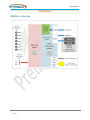
1
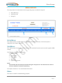
GreenEye Monitor GEM Configuration Manual General GEM Setup Instructions Used in conjunction with one of the following: GEM Setup (No Modules) Doc: GEM-SET GEM Setup (WiFi Only Option) Doc: GEM-SET-W GEM Setup (Ethernet Only Option) Doc: GEM-SET-E GEM Setup (WiFi/Ethernet Combination) Doc: GEM-SET-WE Document Code: GEM-CFG Ver 3.1 2013-05-22 ©Copyright Brultech Research Inc. 2013 Introduction TABLE OF CONTENTS Introduction ................................................................................................................ 4 Overview .................................................................................................................................................. 4 Firmware Upgrade ................................................................................................................................... 4 Requirement ............................................................................................................................................ 4 GEM Setup Overview ................................................................................................... 5 Web Interface Performance .................................................................................................................... 5 Initial Entry ......................................................................................................................................... 5 Slow Page Load ................................................................................................................................... 5 Auto Refresh Pages ............................................................................................................................. 5 Be Patient ........................................................................................................................................... 5 Exit Setup Mode When Done .............................................................................................................. 5 Behavior ................................................................................................................................................... 5 Quick Start ............................................................................................................................................... 5 Entering Setup ............................................................................................................. 6 Requirement ............................................................................................................................................ 6 Menu Groups ............................................................................................................... 7 Setup Menus ............................................................................................................................................ 7 View Menus ............................................................................................................................................. 7 Debug ....................................................................................................................................................... 7 Menu Bar Summary ..................................................................................................... 8 Home Menu ............................................................................................................................................. 8 Channel Option Menu ............................................................................................................................. 8 Channel CT Menu..................................................................................................................................... 8 Temperature Menu ................................................................................................................................. 8 Packet Send Menu ................................................................................................................................... 8 Data Post Menu ....................................................................................................................................... 9 Network Menu......................................................................................................................................... 9 Advanced Menu ....................................................................................................................................... 9 Watt Menu............................................................................................................................................... 9 Watt-Hour Menu ..................................................................................................................................... 9 Status Menu............................................................................................................................................. 9 Download File Menu ................................................................................................................................ 9 Channel Option Menu ................................................................................................ 10 Overview ................................................................................................................................................ 10 PT Settings ............................................................................................................................................. 10 Description ........................................................................................................................................ 10 Setting............................................................................................................................................... 10 Standard or NET Metering ..................................................................................................................... 11 Description ........................................................................................................................................ 11 Setting............................................................................................................................................... 11 Channel Polarity..................................................................................................................................... 11 Description ........................................................................................................................................ 11 Single Channel Polarity ..................................................................................................................... 12 Effect of the PT on Polarity ............................................................................................................... 12 System Frequency.................................................................................................................................. 13 Page 1 Introduction System Phase Option ............................................................................................................................. 13 Channel CT Menu....................................................................................................... 14 Overview ................................................................................................................................................ 14 CT Type ............................................................................................................................................. 14 CT Range ........................................................................................................................................... 14 CT Model ........................................................................................................................................... 14 Multiplier .......................................................................................................................................... 14 Set all channels CTs........................................................................................................................... 15 Set all other CTs ................................................................................................................................ 15 Temperature Menu ................................................................................................... 17 Overview ................................................................................................................................................ 17 Temperature Chan Enable ..................................................................................................................... 17 Setting Temperature Units .................................................................................................................... 17 About Sensor Codes............................................................................................................................... 17 Search and List All Sensors .................................................................................................................... 18 Procedure.......................................................................................................................................... 18 Search, List and Save All Sensors ........................................................................................................... 19 Procedure.......................................................................................................................................... 19 Manually Entering ROM Codes .............................................................................................................. 20 Procedure.......................................................................................................................................... 20 Single Sensor Search and Save............................................................................................................... 21 Procedure.......................................................................................................................................... 21 Packet Send Menu ..................................................................................................... 22 Overview ................................................................................................................................................ 22 What are Packets? ............................................................................................................................ 22 Real-Time ON-OFF ................................................................................................................................. 22 Packet Format ........................................................................................................................................ 22 Primary Packets Format ................................................................................................................... 23 Secondary Packets Format ............................................................................................................... 23 Packet Interval ....................................................................................................................................... 23 Save ........................................................................................................................................................ 23 Input Wattage Simulation...................................................................................................................... 23 Show Packet........................................................................................................................................... 24 Data Post menu ......................................................................................................... 26 Overview ................................................................................................................................................ 26 HTTP GET and POST ............................................................................................................................... 26 POST Channel Selection ......................................................................................................................... 27 Show Packet........................................................................................................................................... 27 Network Menu .......................................................................................................... 28 Overview ................................................................................................................................................ 28 Using DHCP ............................................................................................................................................ 28 Using Static Address .............................................................................................................................. 29 Advanced Menu ........................................................................................................ 30 Overview ................................................................................................................................................ 30 Advanced Commands Block 1................................................................................................................ 30 Advanced Commands Block 2................................................................................................................ 31 Advanced Commands “XBee Module Setup” ........................................................................................ 34 Page 2 Introduction Watt Menu ................................................................................................................ 35 Overview ................................................................................................................................................ 35 Real-Time Power .................................................................................................................................... 35 Watt Hour Menu ....................................................................................................... 36 Overview ................................................................................................................................................ 36 Real-Time Energy ................................................................................................................................... 36 Status Menu .............................................................................................................. 37 Overview ................................................................................................................................................ 37 Debug Menu .............................................................................................................. 38 Debug ..................................................................................................................................................... 38 Quick Start ................................................................................................................. 39 Overview ................................................................................................................................................ 39 Requirements ........................................................................................................................................ 39 Quick Start General................................................................................................................................ 39 Objective ........................................................................................................................................... 39 Important Notes ............................................................................................................................... 39 Steps ................................................................................................................................................. 40 Quick Start Temperature ....................................................................................................................... 41 Pre-Condition .................................................................................................................................... 41 Steps ................................................................................................................................................. 41 Quick Start Pulse Counter ...................................................................................................................... 41 Pre-Condition .................................................................................................................................... 41 Steps ................................................................................................................................................. 41 Appendix A ................................................................................................................ 42 GEM Block Diagram ............................................................................................................................... 42 Page 3 Introduction GreenEye Monitor INTRODUCTION OVERVIEW The GreenEye Monitor incorporates a web interface for setting up parameters. The built-in web server allows a browser to connect to the GEM to perform the setup process. Early GEM models did not have this capability. GEMs with firmware versions older than “COM firmware ver 1.70” will not support setup via web interface until the firmware is upgraded. It is recommended to install “COM firmware ver 2.20” or higher. FIRMWARE UPGRADE The procedure for upgrading the firmware depends on the communication option installed in the GEM. A dedicated manual is available for each communication option. The document code for each option is listed below. Communication Option Document Name Document Code No communication module GEM Setup No Module GEM-SET WiFi Only GEM Setup WiFi Only Option GEM-SET-W Ethernet Only GEM Setup Ethernet Only Option GEM-SET-E WiFi / Ethernet Combination GEM Setup WiFi/Ethernet Combination GEM-SET-WE Indirect Communication via the DashBox GEM Setup Via DashBox GEM-SET-DB Table 1 REQUIREMENT This manual provides the procedure for setting up the GEM parameters once the hardware has been installed. This implies that the following installation steps have been completed: Page 4 The current transformers (CT) are installed and connected to the GEM terminals The potential transformer (PT) is connected The GEM is powered from the 5V power supply The GEM is connected to a network via Ethernet connection GEM Setup Overview GEM SETUP OVERVIEW WEB INTERFACE PERFORMANCE The performance of the setup interface is greatly improved by setting the GEM to “115200” baud. The “baud rate” is the speed at which the GEM communicates with the browser. Early versions of the GEM used “19,200” baud exclusively however newer versions of the firmware provides a means of increasing the communication speed to “115,200”. The baud rate may be changed using the setup interface or using the GEM Network Utility program. Initial Entry Opening the web interface may require clicking the browser’s address bar a couple of times with a long pause in between. Once “Setup Mode” is entered, the performance will improve since the GEM will then focus its resources on the interface. Slow Page Load The web interface is a bit slow at loading pages therefore wait until a page is fully loaded before clicking another menu. If a page fails to load properly, simply wait a couple of seconds and refresh the browser. Auto Refresh Pages The “Watt” and “Watt-Hour” pages are automatically refreshed every eight seconds. When switching to another menu from either one of these two menus, the page may not respond properly. Simply wait and refresh the browser’s page and a proper display will eventually result. Be Patient Try to avoid clicking any page buttons several times. Sometimes there will be a couple of seconds delay before the page loads. Exit Setup Mode When Done It is important to properly exit “Setup Mode” when done to allow the GEM to return to normal operation. BEHAVIOR When entering “Setup Mode”, the GEM stops sending packets or “keep-alive” characters Packet send will resume when “Setup Mode” is exited If web setup pages are inactive for 15 minutes, the GEM will automatically exit “Setup Mode” and resume sending packets If “Watt” or “Watt-Hour” menu is selected and “Setup Mode” is not properly exited, the GEM will not automatically exit this mode due to the auto-refresh nature of these two menu options. Closing the browser will allow the GEM to exit “Setup Mode” after 15 minutes. QUICK START Quick start instructions are provided in the “Quick Start” chapter on page 39. Page 5 Entering Setup ENTERING SETUP REQUIREMENT This section assumes that a connection has already been established between the GEM and a PC and that the “Web Interface” is displayed in the browser as shown in Figure 1 or Figure 2. If this is not the case then refer to the appropriate setup document in Table 1 on page 4 for instructions on how to access the GEM setup page. The specific manual required to do this is based on the communication option installed in the GEM. Figure 1 Figure 2 If the bowser opened up but nothing appeared it may be an indication that the GEM’s firmware is an older version which does not support the web setup page. To resolve this issue, upgrade the GEM firmware. The procedure for upgrading the firmware will be found in the document listed in Table 1. Page 6 Menu Groups MENU GROUPS The setup website is broken down into three general groups as outlined in Figure 3. Setup Menus (1) View Menus (2) Debug (3) Figure 3 SETUP MENUS The “Setup” menus are used to view and modify various GEM parameters. Each menu option is explained in the chapter “Menu Bar ” VIEW MENUS The “View” group of menus are used to view current input data from the sensors as well as general GEM settings. The following sensor data is displayed: Power (watts) Temperature Pulse Counts Watt-Hour Elapsed WH minutes NOTE: This viewable data should only be viewed during the setup process. This should not be used as a real-time method of continuous monitoring. See chapter “Menu Bar ” for more detailed information. DEBUG This section is used for troubleshooting purposes. Page 7 Menu Bar Summary MENU BAR SUMMARY This chapter provides a brief description of each menu option listed in the menu bar (Figure 4). A more detailed explanation for each menu is provided further on in this document. Figure 4 HOME MENU This menu has no real function other than providing a brief description of the web interface. This is the default page when “Setup Mode” is entered. CHANNEL OPTION MENU This section is used to configure parameters that affect all 32 power monitoring channels such as: System voltage setting Channel polarity System Frequency (50Hz or 60Hz) System Type (Single or Three Phase) These parameters should be the first ones to be set. CHANNEL CT MENU “CT” stands for “Current Transformer”. The CTs are the sensors used to monitor the current flow of each load. There are many different CT models available depending on the load current and installation type. This section is used to inform the GEM as to the CT model connected to each individual channel. It also serves to set other channel parameters when used for 3-phase monitoring. TEMPERATURE MENU If the installation uses temperature sensors, this section provides a means of configuring each sensor. PACKET SEND MENU A “packet” is a block of data representing up-to-date measurements of all channels. In a typical system, the GEM is setup to send data updates to the hosting site, device or computer at a pre- determined interval. There are also different formats or structures for the packets depending on the requirements of the data host system. This section is where these parameters are set. Page 8 Menu Bar Summary DATA POST MENU If the GEM transfers data to the host using the network or internet an HTTP post is used. There are various methods of posting such as GET, PUT or POST. Various public data hosts specify unique posting method. The required method is selected in this section as well as specifying the domain name or IP address of the host. NETWORK MENU This section is used to connect the GEM to a network or host. Although it will work with the GEM-E model it is recommended to use the “GEM Network Utility” instead unless the PC being used is a Mac or Linux system. ADVANCED MENU The “Advanced” section allows changes to system specific parameters or provides non-standard commands. It is recommended not to use some of the functions on this page unless fully understanding its functionality. WATT MENU This is a display only page. It is used to read the up-to-date wattage of each channel along with the latest temperature and pulse count. This page is automatically refreshed at a given interval (8 seconds by default). WATT-HOUR MENU This is a display only page. It displays the latest “watt-hour” value. This is an incremental value. 1,000 watt-hours = 1 kilowatt-hour STATUS MENU This section is a display only page. It provides overall system setup information. DOWNLOAD FILE MENU This is used to download processors data for troubleshooting purposes. This file is to accompany an email if technical support is required. Page 9 Channel Option Menu CHANNEL OPTION MENU Figure 5 OVERVIEW The “Channel Option” menu section is used to define parameters which affect all 32 channels of the power monitoring section of the GEM. These parameters need to be the setup first before proceeding with “Channel CT” setup. In this section, the following parameters are configured: PT settings Set for “Standard” or “NET” metering Channel polarity Electrical system’s frequency (50Hz or 60Hz) System phase option PT SETTINGS Description “PT” stands for “Potential Transformer”. The “PT” is used to step down the line voltage for voltage sampling. The “PT Type” and “PT Range” values are used to set the step-down ratio to accurately represent the line voltage. The “PT” also provides safe galvanic isolation from panel voltage potentials. Setting Verify the PT setting. This should already be pre-set and the displayed voltage should be in the 120V range for North American residential installations. For standard 120V/240V systems, the displayed voltage should reflect the line voltage of the outlet where the PT (12VAC wall transformer) is plugged. This is already preset to match the PT included in your package. It should display a voltage in the range of 105V to 130V, typically 120V. For Countries with 230V voltage, this box should display in the range of 230V. For 3-phase systems, refer to the GEM 3-phase documentation. Page 10 Channel Option Menu STANDARD OR NET METERING Description NET metering applies to electrical systems which incorporate a power generating source such as solar or wind and sells energy to the power company when the power generated exceeds the power consumed. Monitoring such systems requires that the power meter has the ability to determine the direction of power flow. The GEM therefore provides a polarity to identify the direction of flow. By default, all measured energy consumed is specified as a positive value. Any of the 32 channels may be enabled to indicate the polarity of the measured power. Setting The metering option should be set to “standard” for all channels unless: The system has an inverter and a solar, wind or other generating system sending energy to the electrical grid. The system is 3-phase. If NET metering is not required, all channels should be set to “Standard”. Do this using the following procedure: 1. Check “Set All Channels” 2. Click the “Standard” radio button 3. Click “Save” If NET metering is required (generating power), all channels should be set to “Standard” as described above, then NET metering should be selected one at a time by selecting the channel number, NET radio button then clicking “Save”. Typically the channels set to net would be the “inverter” (solar or wind) and main panel channels. Figure 6 shows channel 5 set for NET metering. Figure 6 CHANNEL POLARITY This option is used to toggle the polarity of a single energy channel. This function is active only if the selected channel is enabled for NET metering otherwise the polarity has no effect. Description It is standard to display consumed energy as a positive value when energy monitoring. If a renewable system is generating more energy than is being consumed, the resulting energy is represented as a negative value. It is quite possible that the polarity is opposite of what it should be. This depends on Page 11 Channel Option Menu how the CT was installed and the CT leads polarity. The PT (wall transformer) polarity will also affect this. It boils down to a 50-50 chance of the polarity being proper. If the displayed polarity is opposite of what it should be then this function is used to toggle the polarity to its opposite state. Rather than altering the CT installation or swapping the CT leads, it is much safer and simpler to correct an improper polarity via this setting. The polarity is displayed when viewing power under the “Watt” menu. Single Channel Polarity Figure 7 This function is used to change the polarity of a NET enabled channel if required. This function is only effective if NET metering is enabled for a given channel. It is used in cases where the power direction (polarity) is improperly displayed. For example, if channel 1 represents the “main panel” and the power value displays “negative” when consuming power and “positive” when generating more power than is being consumed, toggling the channel 1 polarity will change these polarities to reflect positive for consumed energy and negative for generated. Effect of the PT on Polarity It is important to understand that the polarity of the PT will change the polarity of all 32 channels. For instance, if the wall transformer PT is unplugged turned 180 degrees and re-plugged such that the 120V receptacle blades are reversed, all channel polarities will change. See Figure 8. This is only an issue for NET metering enabled channels where polarized values are used. Figure 8 Page 12 Channel Option Menu SYSTEM FREQUENCY Set the “System Frequency” to correspond with the frequency of your service. In North America, 60Hz is the standard. In Europe, most Countries use 50Hz. Click the frequency and clock “Go” to set the new value. SYSTEM PHASE OPTION Set system phase to match that of the monitored system. Standard residential electrical systems typically use Single Phase electrical systems (also called “split-phase” in North America). This is typically the selected option for residential installations. If the installation includes SPLIT-30 model CTs then the “Single Phase (Special CT)” option is used. Single Phase (Special CT) is the same as “Single Phase” with the difference being that it incorporates special CT compensation for SPLIT-30 CTs. If your system does not use SPLIT-30 CTs, then use “Single Phase” option. Three phase electrical service is typical for many commercial establishments and most industrial electrical systems. If using this option, it is important to obtain specific 3-phase documentation from www.brultech.com/software Page 13 Channel CT Menu CHANNEL CT MENU Figure 9 OVERVIEW This page is used to configure the settings for the current transformers (CT). For each of the 32 channels, the following CT parameters are configured: CT Type CT Range CT Model Multiplier Depending on the model of the CT used for a given channel, a “Type” and “Range” needs to be specified. These two values are used to scale the CT output to reflect the proper current. For example a 33mV signal from a SPLIT-200 CT indicates 20A of current flow while the same 33mV from a SPLIT-60 represents 6A. CT Type This value is a multiplier constant based on the current transformer parameters such as turns ratio and burden resistor. This CT Range The “Range” value doubles the displayed power every time its value is reduced by 1. For example if a channel is displaying 200 watts and the CT range is set to “4”, reducing the CT range to “3” will cause the power to display 400 watts. Reducing the range to “2” will change the reading to 800 watts, and so on. CT Model Brultech provides a variety of current transformer options. Each CT has a part number which is considered the “Model”. By using a “Model” to specify the CT, the GEM will automatically insert the appropriate “CT Type” and “CT Range” for this model, simplifying the CT setting process. Multiplier The multiplier has no effect when set to “0”. If it is set to “1”, the CT signal is doubled. This is used for 120V/240V split phase installation (common North American residential service) where a 240V balanced load is monitored with only one CT. Since many 240V loads require two CTs (one for each line), the power is calculated based on 120V for each line. If a 240V load is balanced*, the single CT signal needs to be doubled to simulate two summed CT signal. Page 14 Channel CT Menu *Balanced Load A 240V load is considered balanced when it connects to “Line1” and “Line2” of a 120V/240V panel but has no connection to the panel “Neutral”. With this type of load, the current flowing through “Line1” is identical to that flowing through “Line2” giving it the term “balanced”. Rather than using two CTs to sense the exact same current twice, one CT is used and the GEM is configured with the “Multiplier” setting to double its signal. This is the same as having two CTs on a balanced load. The “Channel CT” menu section (Figure 9) is used to configure each GEM channel to match the current transformers (CT) connected to each channel. Set all channels CTs To speed up the CT setup process, all channels may be configured to the most common CT used. Figure 10 Refer to Figure 10. 1. Check the “Set all channels to selected CT” option (1) 2. Select the desired CT model from the “Select CT” drop-down list (2). This automatically assigns the proper “CT Type” and “CT Range” required for the selected model 3. Click “Save” (3) This will caused all channels to be configured for this CT model. Set all other CTs Set the remaining CT settings using the procedure below and referring to Figure 11. 1. Make sure the “Set all channels” box is un-selected (1) 2. Enter the channel number (2) 3. Select the CT model of the CT connected to this channel (3). The CT type and range will automatically be assigned. If using a CT model which is not in the list, then set the drop-down Page 15 Channel CT Menu list to “Manual Select” and enter the “CT Type” and “CT Range” values corresponding to the custom CT. 4. The “0 = Normal” radio button should be selected unless this channel is using only one CT to monitor a 240V load. Note that only certain 240V loads can be monitored with only one CT 5. Click “Save” (4). Verify the changes in the listing Figure 11 Page 16 Temperature Menu TEMPERATURE MENU Figure 12 OVERVIEW This page is used to: Enable Temperature channels Search and Set the sensor ROM codes Set the desired temperature units (F or C) TEMPERATURE CHAN ENABLE The box in Figure 13 allows the user to enable any of the eight channels (1). A temperature channel is enabled by checking the “Enable” (2) checkbox on the right. Once the desired temperature channels are enabled, click “Save” (4). Figure 13 SETTING TEMPERATURE UNITS The temperature may be specified in degrees Fahrenheit “F” or Celsius “C” as shown in Figure 13 (3). Once this option has been selected, click “Save” (4). ABOUT SENSOR CODES The “Sensor ROM Code” refers to a unique serial number code programmed into the 1-Wire temperature sensor when it is manufactured. Since these sensor communicate over a common bus, the data from each is identified based on each ROM code. For this reason, it is necessary to provide the GEM with the ROM code of each connected sensor. Page 17 Temperature Menu The GEM provides various methods of reading and saving the ROM codes of the sensor: Searching all sensors Reading one sensor at a time Manually entering the ROM code if provided with the sensor SEARCH AND LIST ALL SENSORS This function is used to discover and list all sensor codes discovered without saving them to a channel. The reason for searching without saving is to prevent issues when adding more sensors. For example, if three sensors are already installed and a new sensor is added, the search function may place the newly found sensor in the “channel 2” location. This would displace the existing “channel 3” sensor to “channel 4” and the existing “channel 2” sensor to “channel 3”. This cannot be avoided since the order of the sensors discovered is based on the search algorithm. In order not to disturb the existing sensor channels, the option to “Search and List” is used allowing the sensor code to be discovered and listed. The sensor may then be manually saved to a user assigned channel. This is described later in this chapter. Procedure Make sure at least on temperature sensor is connected to the 1-Wire bus terminals. Refer to Figure 14. Select the “Search, List all sensor codes” (1) option and click “Go” (2) After a couple of seconds the ROM code for each should be found and displayed as shown in Figure 14 (3) Notice that this option did not assign the found sensor to channel 1 (4). This is because this function was for searching and listing only. Figure 14 Page 18 Temperature Menu SEARCH, LIST AND SAVE ALL SENSORS This option should only be used initially. When new sensors are added, the “Search and List All Sensors” option in the previous section should be used for the reason described in that section. Procedure Make sure at least on temperature sensor is connected to the 1-Wire bus terminals. Refer to Figure 15. Select the “Search, List, Save all sensor codes” (1) option and click “Go” (2) After a couple of seconds the ROM code for each sensor should be found and displayed as shown in Figure 15 (3). Notice that the found code was saved and assigned to the first channel (4). Figure 15 Care must be taken not to use this option when more sensors are added because a newly found sensor might be assigned to channel 1 and the current sensor displaced from channel 1 to channel2. Whether or not this happens depends on the value of the sensor code and the algorithm used. To play it safe, the “Search and List All Sensors” method should be used then use the manual method of entering the ROM code and assigning it to a channel. See section “Manually Entering ROM Codes” section below. Page 19 Temperature Menu MANUALLY ENTERING ROM CODES If the ROM code is known for a sensor, the code can be manually entered and assigned to any of the eight available channels. This is the preferred method when adding sensors to an existing system. This prevents offsetting existing channels where the new sensor may be inserted into an existing used channel if using the automatic method. Procedure If the ROM code of the sensor to be added is no known, use the “Search and List All Sensors” (without the “save” option) procedure to list all of the ROM codes. Make note of the new ROM code. Refer to Figure 16. Select the “Save manually entered sensor ROM code” (1) option Enter the temperature channel number this new sensor is to be assigned to in the “CH” (2) box Enter the eight pair of ROM code characters in the box (3). Make sure each box includes both characters even of the value is “00” Click “Go” (4) Referring to Figure 17, notice that the ROM code (1) was transferred to channel 2 (2) Figure 16 Figure 17 Page 20 Temperature Menu SINGLE SENSOR SEARCH AND SAVE This method involves reading and saving one sensor at a time. This means that only one sensor is connected to the 1-Wire bus at a time. Each sensor is connected by itself on the bus while the “search and save” operation is performed. This option is time intensive but it may be preferred in some circumstances. Procedure Refer to Figure 18. Select the “Search single connected sensor and store in channel specified” (1) option Enter the channel “CH” (2) you wish to have the sensor assigned to Click “Go” (3) to execute the function Figure 18 Page 21 Packet Send Menu PACKET SEND MENU Figure 19 OVERVIEW This menu selection is used to configure the packets of data that is sent to the hosting site or device. The following parameters are configured in this section: Packet enable/disable (ON/OFF) The “Primary” packet format The packet send interval The secondary packet format Enabling/disabling of wattage simulation Viewing of the assembled packet structure Number of ECM-1240 devices to simulate What are Packets? Packets are chunks of data forwarded to the data host at a given interval. The GEM provides various packet formats to accommodate various hosting sites and software. The packets are sent to both, Com1 (primary) and Com2 (secondary) ports. REAL-TIME ON-OFF Refer to Figure 20. The “ON” and “OFF” radio buttons (1) are used to enable/disable the transmission of the packets. When set to “OFF” a “Keep-Alive” string is sent. This is used to keep a TCP-IP connection when the GEM is configured as a client. This may be modified in the “Advanced” menu section. When the page is loaded, the “Real Time Status” button (1) will indicate the current status. Figure 20 PACKET FORMAT The packet format is the structure and syntax of the packet. The format varies based on the requirements and specification defined by the device or site that will be hosting the data. The “drop down” box provides many different options. Page 22 Packet Send Menu Primary Packets Format The “Primary Packet Format” is selected from a drop-down menu (Figure 20-2). If the “Secondary Packet Option” (3) is set to “0: Disabled”, then the primary packets are sent to both “COM1”and “COM2” ports. If the “Secondary Packet Option” is set to a packet option other than “0”, then the “Primary Packets” will be forwarded to COM1 port only and accessible via the following communication modules: RS-232 (COM1) Wifi Only option Ethernet Only option Wifi/Ethernet combination module Secondary Packets Format The “Secondary Packet Format” (3) is selected from the “drop down” box. The “Secondary Packet Format” is limited to packet formats that do not use HTTP posting methods. If the “Secondary Packet Format” (3) is set to “0: Disabled”, then the primary packet will be sent to all COM ports. If a “Secondary Packet Format” is specified (not disabled), then this packet format will be sent to COM2 and will be accessible via the following communication module: RS-232 (COM2) XBee module option The “packet send interval” will be the same as that of the “primary packet”. PACKET INTERVAL The “Packet Send Interval” defines how often the packets are sent. Care should be taken in selecting this value. Consult the data hosting site or host manual for optimum setting. It is important to make sure that the interval setting is not set too low! This will result in packets sent too often. This increases the data traffic and may cause some data host to stop accepting data all together until resolved. If hosting locally, this will cause the host to use excessive storage memory and slow down the charting process. Fifteen second interval works well for most options. NOTE: Currently the “Secondary Packet Interval” (5) takes on the value of the “Primary Packet Interval” (4). SAVE After completing the desired changes, remember to click the “Save” button. This will save all of the settings currently in the “Packet Setup” box. See Figure 20. INPUT WATTAGE SIMULATION WARNING! Do not turn this function “ON” once the GEM is setup and monitoring. Page 23 Packet Send Menu Referring to Figure 21 (1), the “Input Wattage Simulation” is a utility which can be used if no CTs are connected to the GEM and fictional values are required for setup purposes. When this option is selected, all 32 channels will generate wattage values and the watt-seconds and watt-hour values will increment accordingly. Be careful! Enabling this will add fictional data to any valid data of loads which have been monitored. To start this function, click the “ON” button (1) in Figure 21 then click the “Input Wattage Simulation” button. This function may be disabled by using the same procedure just described, but selecting “OFF” button. This function is also automatically disabled if the GEM power is cycled or the GEM is re-booted. Figure 21 Figure 22 shows the effect of enabling the “Input Wattage Simulation” when viewing the “Watt” menu page. The first group of channels one to sixteen (1) generate varying power values while the next group (2) will always show the same power values. These values ignore any CT signals that may be present on the GEM. Figure 22 SHOW PACKET The “Show Packet” utility, Figure 21 (2), is used to view the packet structure of non-binary packet formats. This is helpful during initial setup when posting data over the internet. Figure 23 show the page that appears when the “Show Packet” button is clicked. The entire packet (1) is displayed. Clicking “Refresh Packet” (2) causes all of the data in the packet to be updated. “Return” (3) takes you back to the setup page. Page 24 Packet Send Menu Figure 23 Page 25 Data Post menu DATA POST MENU Figure 24 OVERVIEW The “Data Post” menu section is required if sending HTTP data via the network or internet. If sending data via RS-232, this section is not required. This section has two primary functions: 1. Sets the IP address of the host, along with the required URL extensions, tokens, nodes or whatever is required by the host site. 2. Allows the user to select the power, temperature and pulse channels to be forwarded to the host via HTTP “PUT” method. HTTP GET AND POST The “HTTP Get and Post” section is shown in Figure 25. The “Site Type” (1) drop-down menu provides a selection of various data hosting options currently available (see Figure 26). Depending on the option selected specific data will be required. This is explained in more detail in the instructions for connecting to each site. Typical data required is shown in Figure 25. “URL Address” (2) is the name of the website which accepts the feed. “URL Extension” (3) is the sub directory of the website feed. “Token” (4) or sometimes “Key” is a specific string of characters provided by the hosting site to identify a user account. “Site Node” (5) is sometime used to identify the name given to the GEM. After all values are entered in the “HTTP GET and POST” section, click “Save” (6). Figure 25 Page 26 Data Post menu Figure 26 POST CHANNEL SELECTION This section allows the user to select which power channel data will be forwarded to the hosting site. The box in Figure 27 allows selection of channels one to 24. Once the desired channels have been selected, remember to click “Save”. Figure 27 Figure 28 shows a second selection box for channels twenty-five to thirty-two (1), the temperature channels (2) and the counter channels (3). Again, remember to click “Save” (4) after the selections for this box have been completed. Figure 28 SHOW PACKET The “Show Packet” button as shown in Figure 29 provides the same function as that in the “Show Packet” command in the “Packet Send Menu” menu section on page 24. Figure 29 Page 27 Network Menu NETWORK MENU Figure 30 OVERVIEW IMPORTANT: This page will be visible only if the communication option installed in the GEM is capable of being configured via this web interface. The Wifi/Ethernet combination module has its own dedicated web interface for this purpose and may not be configured using this interface. NOTE: The initial values displayed on this page are not necessarily the values set inside the WiFi module. The displayed values reflect the last saved settings to the module. The actual values may be retrieved from the module using the “Refresh” button. This function takes several seconds to complete. USING DHCP The “Network” setup page with the “DHCP” option selected is shown in Figure 31. The “DHCP” option is commonly used when configuring the network because the following parameters are automatically assigned by the router: Local IP address Subnet Mask Local Gateway The user must provide the following information: “SSID” (1) is the name of the WiFi network that the GEM will connect to “Password” (2) is the security password to the WiFi network you are connecting to “Local Port”(4) should be set to port “80” Figure 31 Either the “Remote IP” (5) or the “URL” (6) value will be used for indicating the address of the remote host. If the “Remote IP” (5) is set to “0.0.0.0”, then the “URL” (6) value will be used. An example of a URL is “api.smartenergygroups.com”. “Remote Port” (7) is typically set to port “80” when sending data to a host via the internet. Remember to click “Save” when done! Page 28 Network Menu USING STATIC ADDRESS The “Network” setup page with the “Static” option selected is shown in Figure 31Figure 32. The “Static” (3) option is used when a specific IP address is to be assigned to the GEM. This IP address must be on the same IP subnet as the network the GEM is connected to and must not be used by any other device on the network. It is beyond the scope of this document to elaborate on this. Further information can be found on the internet by searching keywords “assign static IP address local network”. Local IP address Subnet Mask Local Gateway The user must provide the following information: “SSID” (1) is the name of the WiFi network that the GEM will connect to “Password” (2) is the security password to the WiFi network you are connecting to “Local Port”(4) should be set to port “80” “IP” (5) is the local IP address of the GEM. This must be assigned by the user when “Static” addressing is used “Gateway” (6) is the router’s IP address “Mask” is the network’s subnet mask Figure 32 Either the “Remote IP” (8) or the “URL” (9) value will be used for indicating the address of the remote host. If the “Remote IP” (8) is set to “0.0.0.0”, then the “URL” (9) value will be used. An example of a URL is “api.smartenergygroups.com”. “Remote Port” (10) is typically set to port “80” when sending data to a host via the internet. Remember to click “Save” when done! Page 29 Advanced Menu ADVANCED MENU Figure 33 OVERVIEW The “Advanced” menu section consists of various commands and provides the option to change various settings. Some settings should only be made providing the user has a good understanding of the function. ADVANCED COMMANDS BLOCK 1 Figure 34 shows the first block of advanced commands. Each is described below. “Reset WiFi Module” (1) sends a hardware reset signal to re-boot the communication module connected to COM1. Although labeled as “Reset WiFI”, this function will reset the Ethernet module for “Ethernet Only” options “Reset ZigBee” (2) sends a hardware reset pulse to the “XBee” module if one is installed “Reboot COM” (3) reboots the GEM’s main processor “Reboot ENG” (4) reboots the power metering section of the GEM “Reset Watt-Seconds and Seconds” (5) resets the incremental watt-second counter and three byte seconds counter “Reset Pulse Counters” (6) zeros the incremental count value of all four pulse counter inputs “Reset All Counters” (8) zeros the following incremental values: o Watt-second counters o Seconds counter (unrelated to the calendar clock seconds) o Watt-hour counters o Minute counter (unrelated to the calendar clock minutes) o Pulse counters Figure 34 Page 30 Advanced Menu “Reset Watt-Hour Counters” (9) resets the incremental Watt-hour values including the corresponding accumulated Watt-hour minutes. “COM1 Baud” (10) provides selection of the baud rate for COM1 which is connected to the WiFi and/or Ethernet module. The baud rate is selected then the “Go” button must be clicked. “19200” baud is required for firmware upgrades otherwise “115200” baud is recommended “Packet Chunk Size” (11) is the maximum number of bytes buffered before a chunk of data is sent during packet send or web interface communication. It is recommended to keep this value set to “2047”. Never use a value greater than 2047. “Packet Chunk Interval Time” (12) is the amount of pause time between chunks of data. This provides time for some communication modules to process a chunk of data before sending it another chunk. The recommended value is between 200 and 800 unless specified differently for a given module. Each unit represents several microseconds “Calendar Time and Date” (13) sets the system time. Clicking “Get Local Date” reads the computer time and “Get UTC Date” reads the “Coordinated Universal Time” (UTC) which is the primary time standard by which the world regulates clocks and time. Once one of the two time option is selected, it can be saved to the GEM by clicking the “Save Date to GEM” “Keep Alive String” (14) is a one to eight character string which is sent when real-time packet send is turned “off”. See Real-Time ON-OFF on page 22 “Keep Alive Pulse” (15) provides a means of disabling the keep-alive function. If disabled, there will be no data communicated if Real-Time Packet send is set to “Off”. Care must be taken not to disable this if the GEM is setup as a TCP/IP client since the connection to the server may be lost permanently. “Reset Wh on Post” (16) works in conjunction with posting HTTP data to some sites such as “Smart Energy Groups”. When this is enabled, the accumulated watt-hour value is reset to zero after every packet send. This causes the watt-hour value to represent the number of watt-hours used since last packet send. If disabled, the packet will contain an incremental value or wattseconds since the last time it was manually reset or the counter has wrapped around. “Watt-Hour Decimal/Integer” (17) If decimal is selected, the watt-hour value sent during a post will have a value up to two decimal places. “Decimal” option is recommended. Example: o Decimal: 23.35 watt-hour o Integer: 23 watt-hour ADVANCED COMMANDS BLOCK 2 Figure 34Figure 35 shows the second block of advanced commands. Each is described below. “Disable Chan 33-48 Post” (20) is no longer used “COP Test” (21). It is recommended not to use this test. This command puts the GEM in an endless firmware loop for test purposes. “COM1 Flow” (22) enables/disables hardware flow control for the COM1 serial port. This should be enabled for the following communication options: “WiFi Only” and “WiFi/Ethernet Combo” Page 31 Advanced Menu “COM2 Flow” (23) enables/disables hardware flow control for the COM2 serial port. This should be enabled only if an “XBee” module is installed. Figure 35 “WiFi Auto Reset Timer” (24) this function sends a timed hardware reset pulse to the communication module connected to COM1. This includes the “WiFi Only”, “WiFi/Ethernet Combo” and “Ethernet Only” modules. This function should only be used with the “WiFi Only” module option under certain circumstances. The value specified is the number of seconds between reset pulses. The purpose of this function is to be able to recover from certain situations where loss of communication occurs. A value of “0” disables this function which is recommended unless recommended in the “WiFi Only” setup manual. “WiFi No Response Counter” (25) this function sends a reset pulse to the communication module connected to COM1. This includes the “WiFi Only”, “WiFi/Ethernet Combo” and “Ethernet Only” modules. This function should only be used with the “WiFi Only” module option under certain circumstances. The value specified for this function is the number times that a packet has been sent without receiving a response from the server. After the specified number of "no-response", a hardware pulse resets the communication module. A value of “0” disables this function which is recommended unless recommended otherwise. “COM2 Auto Reset Timer” (26) this function sends a timed hardware reset pulse to the “XBee” module. The value specified is the number of seconds between reset pulses. The purpose of this function is to be able to recover from certain situations where loss of communication occurs. A value of “0” disables this function which is recommended unless recommended otherwise. “COM2 No Response Counter” (27) this function sends a reset pulse to the “XBee module" connected to COM2. This includes the “WiFi Only”, “WiFi/Ethernet Combo” and “Ethernet Only” modules. The value specified for this function is the number times that a packet has been sent without receiving a response from the server. After the specified number of no-response, a hardware reset pulse is sent to the XBee module. A value of “0” disables this function which is recommended unless recommended otherwise. Page 32 Advanced Menu “Get Idle Time” (28) The “Idle Time” is the amount of time of no signal that the communication modules closes the TCP/IP connection. This function reads this value from the communication module. “Idle Time Sec” (29) The “Idle Time” is the amount of time of no signal that the communication modules closes the TCP/IP connection. This function sets the communication module with the specified number of seconds. “Backup Data” (30) function is used to backup all of the data before removing the battery. After clicking “Go” for this function, the page in Figure 36 is displayed providing instructions. Figure 36 “Real-Time Refresh Rate” (31) sets the frequency at which the “Watt” and “Watt-Hour” menu page of the GEM Setup is refreshed. By default, the data is refreshed every “8” seconds. The lowest allowable refresh rate is “3” seconds. Assigning a value lower than “3” sets the value to “8” second. “Display Comp” (32) only applies if the “Single Phase (Special CT)” option is enabled on page 13. Clicking this function will cause the “compensation” setting to be displayed in the “Channel CT” section. This option remains active only until the GEM is rebooted. Figure 37 shows how the CT settings page is displayed under normal circumstances when the “Single Phase (Special CT)” option is used. Once the “Display Comp” option is enabled, the same page will display an additional column (1) in Figure 38. Notice that the SPLIT-30 CT (2) has a compensation value of two (3). Figure 37 Figure 38 Page 33 Advanced Menu ADVANCED COMMANDS “XBEE MODULE SETUP” This advanced block is used for GEM devices with an “XBee” module installed for “ZigBee” wireless communication. See Figure 39. Figure 39 “Set ZigBee for Brultech” (1) sets the settings of the XBee module to the Brultech default values. “Set ZigBee for ISY” (2) sets the settings of the XBee module to communicate with Universal Device Inc.’s “ISY” home automation and energy management system “Custom ZigBee AT String” (3) allows the XBee module to be configured to custom parameters. The GEM uses the “AT” version of the "Digi International (digi.com)" XBee module with “ZB” firmware. The AT command set is listed in Digi’s manual for the XBee module. Care should be taken not to change the module’s baud rate which is set to “19200”. Page 34 Watt Menu WATT MENU Figure 40 OVERVIEW The “Watt” menu (Figure 40) opens a page which displays: The Watt value for channels 1 to 32 The power-line Voltage The Temperature The Pulse Counter values This page should only be used for setup and troubleshooting purposes. REAL-TIME POWER The “Watt” page is displayed in Figure 41. This page is automatically refreshed every 8 seconds (by default) with up to the date data. The refresh frequency can be changed by the “Real-Time Refresh Rate” function in the “Advanced Commands Block 2” chapter on page 31. Figure 41 Page 35 Watt Hour Menu WATT HOUR MENU Figure 42 OVERVIEW The “Watt-Hour” menu (Figure 40Figure 42) opens a page which displays: The Watt-Hour energy value for channels 1 to 32 The power-line Voltage The Temperature The Pulse Counter values This page should only be used for setup and troubleshooting purposes. REAL-TIME ENERGY The “Watt-Hour” page is displayed in Figure 43. This page is automatically refreshed every 8 seconds (by default) with updated data. The refresh frequency can be changed by the “Real-Time Refresh Rate” function in the “Advanced Commands Block 2” chapter on page 31. Figure 43 Page 36 Status Menu STATUS MENU Figure 44 OVERVIEW The “Status” page is shown in Figure 45. This page provides information on some of the GEMs settings. Most of the information listed is self-explanatory. Each of the settings displayed is explained in this various sections of this manual. One parameter that is not displayed elsewhere is the “Hardware Configuration”. “Hardware Configuration” shows the parameter which indicates which communication module is installed in the GEM. It is important that this setting matches the actual installed hardware. If this is not set properly, the GEM will not communicate properly with the module and can also cause excessive battery drain when power is removed from the GEM. Figure 45 Page 37 Debug Menu DEBUG MENU Figure 46 DEBUG The “Download File” option provides a means for analysis of the system status and settings. This file should be forwarded to Brultech support if any issues are experienced, along with a description of the problem. Page 38 Quick Start QUICK START OVERVIEW This chapter provides “to the point” instructions for setting up the GEM. For any function, more information may be found in this manual if something is unclear. REQUIREMENTS GEM installed with sensors connected The GEM setup document corresponding to the GEM communication option installed. Refer to Table 2 COM Firmware version 2.21 or greater installed GEM Network Utility Software (ver 4.2 or better) installed on the PC Communication Option Document Name Document Code No communication module GEM Setup No Module GEM-SET WiFi Only GEM Setup WiFi Only Option GEM-SET-W Ethernet Only GEM Setup Ethernet Only Option GEM-SET-E WiFi / Ethernet Combination GEM Setup WiFi/Ethernet Combination GEM-SET-WE Indirect Communication via the DashBox GEM Setup Via DashBox GEM-SET-DB Table 2 QUICK START GENERAL Objective Connect to the GEM with PC/Browser Setup System and CT settings View active channel wattage. Important Notes Please note that the GEM’s setup interface may require a few tries to successfully enter initially. Always wait for the browser pages to fully load before selecting a different menu. Page 39 Quick Start Steps The following steps are based on the GEM installed on a 120V/240V residential split-phase panel. 1. Follow the steps in the “GEM Setup” manual selected from the list in Table 2 on page 39 2. Follow the instruction to the point where the GEM Setup page is opened in a browser as shown in Figure 47 or Figure 48 Figure 47 Figure 48 3. Once the GEM setup page is entered, select “Channel Options” menu. a. Make sure the voltage display in the neighborhood of 110V to 128V. b. Set to “Single Phase” unless your system has SPLIT-30 CTs installed, then set to “Single Phase – Special CTs”. Remember to click “Save” after any changes. c. Make sure 60Hz is selected. 4. Click the “Channel CT” menu option. 5. Determine the most common CT used in the system. Typically this would be Micro-40 CTs. Select this CT model from the “Select CT” drop down list. Check the “Set all channels to selected CT” box then click “Save”. This will cause all 32 channels to assume the values of the specified CT. 6. For CTs other than the specified model, enter the channel the CT is connected to, select the CT from the CT model list and click save. There is one unique exception which applies to 240V loads using only one CT for monitoring. For these, click the “1-CT/240V” button before saving. 7. Click “Watt” from the menu. This page will display the latest power value from each channel. This page is automatically refreshed every 8 seconds. Page 40 Quick Start QUICK START TEMPERATURE Pre-Condition One or more “1-Wire” temperature sensor is connected to the GEM. Steps 1. Enter the web setup page and click the “Temperature” menu. 2. Select the “Enable Checkbox” for the number of connected sensors beginning with channel 1. For example, if two sensors are used, channel 1 and 2 will be checked and channels 3 to 8 unchecked. 3. Select F or C units and click “Save” 4. Click the “Search, List, Save all sensors codes” radio button then click “Go”. This step will discover all sensor ROM codes and assign them to the enabled channels. 5. Click the “Watt” menu to view the temperature value. It will take up to 64 seconds to update all temperatures so please be patient. QUICK START PULSE COUNTER Pre-Condition One or more pulse signals are connected to the GEM Steps 1. Select “Advanced” Menu and click “Reset Pulse Counters” 2. Click the “Watt” menu and observe the pulse counter values. Remember that this page is refreshed every 8 seconds therefore the pulse count will reflect all pulse counts sensed during the 8 second interval. Page 41 Appendix A APPENDIX A GEM BLOCK DIAGRAM Figure 49 Page 42