1
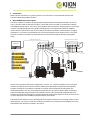
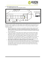
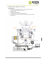
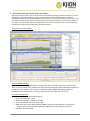
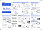
ONYX RADAR Partner Technical Overview Date: 10.02.2014 KJION Technology GmbH Murlingengasse 7 A-1120 Wien Tel.: +43 1 996 20 20 - 0 Fax: +43 1 996 20 20 - 99 GF: A. Dastrandj, DI(FH) P. Scheuermann F/N: FN12644h UID ATU 373 47 705 DVR: 009075 Handelsgericht Wien Raiffeisen Landesbank NÖ-W AG Knt.Nr.: 2.786.184 Blz.: 32 000 IBAN: AT34 3200 0000 0278 6184 BIC: RLNWATWW www.kjion.com [email protected] Skype: kjiontechnologygmbh Table of content 1. 2. 3. Introduction .................................................................................................................... 3 ONYX RADAR General description ............................................................................... 3 ONYX RADAR technical overview ....................................................................................... 4 3.1. 3.2. 3.3. 4. 5. ONYX RADAR Coretec Processing Unit overview ........................................................ 4 Minimal system configuration as an example ............................................................. 5 Measurement system .................................................................................................. 6 Description of the Onyx Control Center PC software ............................................................ 9 Onyx Radar network structure ..........................................................................................10 Partner technical overview - 10/02/2014 2/10 1. Introduction Subject of this document is to give our partners and customers a brief technical and financial overview about ONYX RADAR systems. 2. ONYX RADAR General description The ONYX - Machine Condition Analyzing Expert System Solution developed by Aimtec consists of one or several Coretec Processing Units(PU), connected sensors and the PC visualization software called ONYX Control Center. The system is an adaptive real time process analyzing expert system that is openly conceptualized and thus capable of dealing with a lot of potential problems. Adaptive means that the system learns the current machine condition and adapts automatically to changed conditions. It is an expert system because it can function without human experts and it is real time because it is able to correlate the measurements and calculations without humanly perceptible delay. Serial connection to PC ONYX CC Serial connection to next PU ONXY RADAR Processing Unit ONXY RADAR Processing Unit System OK System OK NO ALARM NO ALARM WARNING WARNING MAIN ALARM MAIN ALARM Sensors (for mechanical vibrations, temperature, current, etc,..) will be hooked on to the analyzed machine and deliver the necessary raw data which will be processed, analyzed and consequently brought to attention. Onyx Radar is capable of instantly and automatically shutting down the observed machine in the case of unexpected major failure. The system is able to detect upcoming mechanical damages long time before they become critical. The system helps implementing and optimizing maintenance strategies to avoid unexpected machine still stands. At all times the user has an exact overview of the condition and performance of his device. The ONYX System Solutions were developed for the long term observance of rotating machinery and other facilities. The system recalls the condition of a device at an early point and compares the early learned data with all data measured in the future. Partner technical overview - 10/02/2014 3/10 3. ONYX RADAR technical overview 3.1. ONYX RADAR Coretec Processing Unit overview Power connection and earth screw 4xRelay Outputs on the rear side PC (e.g. Laptop) with installed Onyx ControlCenter software ONXY RADAR Processing Unit System OK NO ALARM WARNING MAIN ALARM 4xHigh speed analogue sensor input (e.g. Vibration) 8x Universal sensor input (e.g. Vibration RMS sensor 4-20mA input) 2x Rs422 communication interfaces 4x Status LEDs This system comprises 4 high-speed signal inputs, 8 universal signal inputs and 4 relay-outputs. For the power supply a voltage of 115…230V, 50/60Hz, 10W is needed and for configuration of system parameters a serial RS422 communication to a PC which is running the ONYX CONTROL CENTER software is needed. High-speed signal inputs: This option is only needed for spectral analysis. Vibration-sensorsignals are sampled at a rate of 27kHz and digitally processed into a CPB-spectrum from 0.16Hz to 10kHz as well as into various other derived measurement-values. Resolution is 16 bits, accuracy 0.1%. For details please refer to the spectral computation method description later in this document. Universal signal inputs: A wide range of sensor-signals can be connected to these inputs – including DC-voltage (e.g. temperature-sensors with 10mV/°C), DC-current (e.g. 4-20mA RMS-vibration-sensors, anemometer-wind-sensors, AC-drive-current-sensors), resistive sensors (e.g. PT100 or strain-gauge-bridges) or digital input signals (contacts or pulses measuring events, pulse-width, period, frequency – e.g. rotating wind sensor, duty cycle or operating time). A new measurement-value is collected every 300ms on each of the 8 universal inputs. Analogue inputs have a resolution of 13 bits and an accuracy of 1%, the time-resolution of digital inputs is 25,6us and their accuracy is better 0.01%. Relay-outputs: each relay can be individually assigned to each measurement-value or any group of measurement-values (linked by logical OR or AND). Over- and understepping of up to 4 thresholds per measurement-value are monitored every 300ms, optionally combined with logical NOT. Also the time an alarm-condition must continue before relay-alert is individually selectable per measurement-value. Each relay-output consists of one switchover-contact rated 250V/2A. Partner technical overview - 10/02/2014 4/10 3.2. Minimal system configuration as an example IN and OUTPUTS: 1x wind sensor input (light version or maintenance free version) 4x 4-20mA T-RMS vibration sensor input 4x Relay output 1x ONYX CC Basic Software 1x communication cable for connection to a PC 2 x optional reserve universal inputs for measuring e.g. drive currents, temperatures….. Main Bearing TOWER BASE Electric Motor 2 Rotary Joint Electric Motor 1 Ambient wind speed sensor ONYX CC USB ONXY RADAR Processing Unit Rs422 Partner technical overview - 10/02/2014 5/10 3.3. Measurement system Every measurement value within the system has 4 thresholds. 2 low thresholds and 2 high thresholds. Normally only the 2 high thresholds are used. These are a yellow one which has the characteristic of a warning and a red one which indicates a serious problem. As described in the ONYX CC user manual it is possible to define through this PC software which of the 4 relay outputs should react in case that any of the thresholds is surpassed. This extraordinary flexibility allows an optimal system configuration suitable for any needs, e.g. Relay 1 action should occur in case of a wind speed more than 100km/h and Relay 2 action should occur in case of more than 150 km/h wind speed. Additionally every threshold has the function of “Alarm Count” and “Alarm Time“ - Alarm Count means that the alarm condition must be fulfilled this number of times consecutively to trigger an alarm. Alarm Time means that the alarm condition must be fulfilled this period of time to trigger an alarm. Both criteria must be fulfilled in order to trigger an alarm. With this setting single peaks that would lead to false alarms can be suppressed very flexible. Performance parameters of the Coretec Processing Unit Microcontroller based vibration analyzing instrument, which is designed to permanently monitor the vibrations and other important parameters of a machine in order to set up a condition based and therefore predictive maintenance system. The connector amount can vary due to different system configurations Advantages: Up to additional 16 digital input channels to connect e.g. oil debris-, temperature, revolution, RMS 4-20mA sensors. Built in reliable alarm giving function for all connected sensors. Up to 4 Relay outputs for e.g. emergency shutdown of valuable machinery Compact industrial housing with 3 Alarm LEDs and 1 active LED. Very flexible and dependable alarm giving functionality independent of operating condition. Realize large multi sensor networks by serial connecting several Processing units. Easy connection of sensors by standard sensor cable connectors. Easy to use PC software which serves the following functionality: display of all measured data, data analysis, system configuration and data backup. Partner technical overview - 10/02/2014 6/10 The Processing Unit doesn’t need a PC for the daily operation. Upgradeable with up to 4 channels vibration spectrum surveillance from 0,1Hz to 10kHz via a 256 lines CPB spectrum which is computed in real time. Upgradeable with dataset logging functionality in order to be able to make trend analysis over a long period of time. Upgradeable with a possibility to connect to user defined host systems in order to be able to transmit measurement values to other systems. Upgradeable with the possibility to connect Aimtec’s lightning stroke sensors. Technical Performance: Computing power Non volatile memory for data and configuration Standard serial interfaces Environmental Ingress Protection Operating temperature range EMC compliant CE compliant Housing Size (without connectors) 80 Mips 2 MB 2xRS422 IP65 -40°…+75°C 260 x 160 x 90 mm Display High Efficiency alarm LEDs green/yellow/red High Efficiency activity LEDs blue Change of display color happens if any threshold is exceeded and all alarm parameters are fulfilled. Electrical Supply 115..230V 50/60Hz 10W other voltages on demand All sensors and communication lines are pluggable with IP67 industrial connectors. Serial system design Two or more Processing Units can be serially connected together in order to form a Processing Unit-network. A standard 8pin-sensor-cable can be used for this Spectral computation method used for the 4 high speed signal inputs The computation method of the spectrum is called Constant Percentage Bandwidth (CPB) The frequency scale of the spectrum is logarithmic The Processing Unit is computing a CPB with a 4.4% displacement from one line to the other The whole spectrum (0.1 Hz…10 kHz) is displayed with 256 frequency lines in real time This spectrum analysing method enables the system to detect the slightest errors weeks or months before they become obvious. Partner technical overview - 10/02/2014 7/10 Reliable Alarm Generation Learns – the system can learn the actual status of the mechanical parts of a radar Saving and using of up to 19 different reference conditions (“Learns”) Automatic generation of thresholds according to the actual condition of the machine Automatic learn generation and switching (e.g. using different Learns for winter and summer) Alarm Pattern Recognition The actual overall condition of the machine is compared to all saved overall conditions, which once caused an alarm. If the similarity to one alarm condition exceeds a certain amount, an alarm will be raised. Alarm Suppression Defined machine conditions do not generate alarms (e.g. start up). Alarm generation depends also on duration and number of alarm conditions (single or short time events can be suppressed). Onyx Control Center(CC) Software Modules ONYXCC Module 1 –Basic PC Software module License Basic configuration settings and Human interface to the Processing Unit Setting alarm thresholds and functions for all connected sensors Possibility to connect T-RMS 4-20mA vibration sensors to the Processing Unit and setup all alarm and threshold functions for these sensors Possibility to use the system as a protection system based on the T-RMS vibration values – e.g. turn off the radar station caused by too high vibrations ONYXCC Module 2 – Vibration Spectrum measurement and analysis upgrade Using the 4 high speed vibration inputs of the processing unit Calculate a vibration spectrum out of up to four connected vibration sensors and therefore realize a preventive maintenance system for the mechanical parts of radar stations Use the built in vibration spectrum analyzing functions to analyse any vibration spectrum and alarms which occurred. ONYXCC Module 3 – Dataset function upgrade The Processing Unit can be configured to generate and save data records which include: patterns, trends, mean values, minimum values, maximum values, spectral data, alarm status, thresholds, actual-Learn, and the measurement value names and units. The Processing Unit can store up to 400 datasets in its flash memory. Possibility to store all data of the connected sensors at a defined dataset interval Generate long term trends based on stored data Use the third party software Greeneye to visualize trends Data export function for all measurement values ONYX CC Module 4 – Host connection via SNMP upgrade All information of the ONYX RADAR system can be read out by a host system based on the SNMP protocol standard. Partner technical overview - 10/02/2014 8/10 4. Description of the Onyx Control Center PC software The Onyx Control Center is the PC-User Interface Software for all Onyx Systems Solutions. It serves the display of all measured data, analysis, configuration and data backup. ONYX CC offers a complete overview of the observed machinery at all times. If a PC is permanently connected to the CT network, all data generated by the Coretec Units will automatically be stored on the hard drive of the PC. The system also works PC independent so that the surveillance and a consistently data recording over the whole machine life can be guaranteed. Screenshot of the PC-software: ONYX CC SNMP Interface In order to implement the data which is produced by the Onyx Radar system into a host system which is mostly used by radar operators as their central monitoring system KJION has developed an interface to such systems. The interface is realized through a SNMP-agent(Simple Network Management Protokoll) which is running on the same PC where Onyx CC is running. PC System Configuration Operating System: Windows XP/Vista/7 Processor Frequency: 1 Ghz Necessary Interface: 1xRS422 or 1x USB Screen Resolution minimum: 1024 x 768 Hard drive space used: aaproximately 30MB is used for dataset backups. If the minimal dataset interval of 76 seconds is used then 3GB/Year/Processing Unit is required. Software: Acrobat Reader Partner technical overview - 10/02/2014 9/10 5. Onyx Radar network structure The Onyx Radar(Coretec) Processing Unit, which is installed near the rotating antenna is connected to a PC in the control room(as an option a SNMP Agent is running on this PC), with its own mass storage and an IP-address under which it can be reached. This PC has the following functions: Storing of all data Providing a SNMP interface for the CMOS system Providing connection to all Onyx Radar functions by accepting remote desktop (This is technique which allows a user to take over another computer as if he would sit in front of it by himself) connections from the central PC as well as from a portable laptop. Advantages: Consistent connection to all Onyx data (real time as well as historical data) from within your whole TCP/IP network Each Onyx system at each radar site can provide its data directly to a host system via SNMP agent or directly with relay outputs. A usual scenario would be: Onyx recognises an Alarm The SNMP Agent sends this event to the host system where the Alarm is recognised Get a deeper look at the alarm-data Use the Central PC or any Laptop with the remote desktop software to connect to the Onyx system The network load for one open remote desktop connection is around 13 KB/second average (download: from the radar station to a optional central monitoring PC). If the connection speed falls beyond this limit the only technical consequence is that the user will experience a freezed picture on his screen for a short time. The same specification applies to any other computer which connects to the Onyx Radar Processing Unit (e.g. maintenance Laptop) It will not be necessary to instantly open the remote desktop connections (to the three radar stations) on the central monitoring PC. The connections should only be opened if the SNMP agent recognises an alarm, in order to have a deeper look at the cause of this alarm. This means that it is not necessary that there is a permanent data flow between the central station and the three Onyx Radar Processing Units. Partner technical overview - 10/02/2014 10/10