1
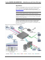
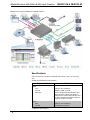
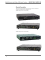
Crestron IM-RXV1-M & IM-RXV3-M iMedia Receiver with Video and Mic Input Operations & Installation Guide This document was prepared and written by the Technical Documentation department at: Crestron Electronics, Inc. 15 Volvo Drive Rockleigh, NJ 07647 1-888-CRESTRON All brand names, product names and trademarks are the property of their respective owners. ©2007 Crestron Electronics, Inc. Crestron IM-RXV1-M & IM-RXV3-M iMedia Receiver with Video & Mic Input Contents iMedia Receiver with Video and Mic Input: IM-RXV1-M & IM-RXV3-M 1 Introduction ............................................................................................................................... 1 Features and Functions ................................................................................................ 1 Applications................................................................................................................. 3 Specifications .............................................................................................................. 4 Physical Description.................................................................................................... 6 Industry Compliance ................................................................................................. 11 Setup ........................................................................................................................................ 12 Network Wiring......................................................................................................... 12 IM Wiring.................................................................................................................. 12 Identity Code ............................................................................................................. 13 Installation ................................................................................................................. 14 Hardware Hookup ..................................................................................................... 15 System Configuration .............................................................................................................. 16 Earliest Version Software Requirements for the PC ................................................. 16 iMedia Wizard Configuration.................................................................................... 16 Uploading and Upgrading........................................................................................................ 17 Establishing Communication..................................................................................... 17 Firmware ................................................................................................................... 18 Program Checks ........................................................................................................ 18 Problem Solving ...................................................................................................................... 19 Troubleshooting......................................................................................................... 19 Reference Documents................................................................................................ 19 Further Inquiries ........................................................................................................ 20 Future Updates .......................................................................................................... 20 Software License Agreement................................................................................................... 21 Return and Warranty Policies .................................................................................................. 23 Merchandise Returns / Repair Service ...................................................................... 23 CRESTRON Limited Warranty................................................................................. 23 Operations & Installation Guide – DOC. 6593A Contents • i Crestron IM-RXV1-M & IM-RXV3-M iMedia Receiver with Video & Mic Input iMedia Receiver with Video and Mic Input: IM-RXV1-M & IM-RXV3-M Introduction Crestron's iMedia (IM) provides an extremely simple and affordable multimedia presentation control solution for small conference rooms and training rooms. No comparable solution comes close to matching iMedia's speed and ease of installation, intuitive operation, and incredibly low cost. Models with one (IM-RXV1-M) or three (IM-RXV3-M) IM transmitter inputs are available. Features and Functions • • • • • • • • • A simple, affordable solution for single-display multimedia presentation iMedia Transport for fast and easy single-cable installation Supports XGA resolution up to 84 feet, and UXGA up to 34 feet Supports composite video signals Built-in LAN, RS-232, IR, relays and digital input control ports Audio line input for wireless microphone Built-in 20 watt stereo amplifier and line-level outputs Complete setup in minutes using iMedia Wizard Software Built-in Web server supports e-Control®2 and RoomView® Operations & Installation Guide – DOC. 6593A iMedia Receiver: IM-RXV1-M & IM-RXV3-M • 1 iMedia Receiver with Video & Mic Input Crestron IM-RXV1-M & IM-RXV3-M The iMedia Transport The iMedia transport utilizes a single CAT5e* type cable to transmit computer RGB, video, and stereo audio signals to a single display device. A typical XGA signal (1024 X 768 pixels at 60 Hz) can be transmitted up to 84 feet using iMedia, while higher resolutions up to 1600 x 1200 can be handled over shorter distances. Composite video signals can be transmitted up to 218 feet. Audio is transmitted digitally at 20-bit, 48 kHz resolution. Control and power signals are also contained on the same wire, eliminating the need for separate control or power cables. * For iMedia use CresCAT-IM cable, or quality CAT5e/CAT6 cable having a maximum delay skew of 15ns per 100m. iMedia Recevier Mounted at the display device, the IM-RXV1-M and IM-RXV3-M receive the iMedia signal from up to three IM transmitters, breaking out the RGB, video, audio, and control signals for connection to the display device. Adjustable bandwidth compensation is provided to maximize image quality over long cable runs. Integrated Amplifier The IM-RXV1-M and IM-RXV3-M include a built-in 20 watt stereo amplifier to drive a pair of 8 ohm speakers. Balanced line level outputs are also provided to allow the audio signal to be connected directly to inputs on the display device or fed to a pair of powered speakers. Onboard digital signal processing affords adjustment of audio levels, plus bass, treble, and balance settings at setup via software. Wireless Microphone Input The inclusion of a balanced line input allows the connection of a wireless microphone receiver, audio mixer, or mic preamp to support speech reinforcement capabilities. Microphone level is adjustable right at the IM transmitter by holding the SELECT button and turning the VOLUME knob. Display Control The IM-RXV1-M and IM-RXV3-M contain both IR and bidirectional RS-232 ports to enable full control of the display device. Two relay ports are also included for control of a projection screen or lift. In addition, the three digital input ports can accept the direct connection of room occupancy sensors and power sensors for enhanced automation and monitoring. e-Control®2 and RoomView® Despite their simple design and low cost, the IM-RXV1-M and IM-RXV3-M support Crestron's powerful e-Control 2 XPanel and RoomView applications, delivering the industry's best help desk and resource management solution for any number of rooms equipped with iMedia. Fast, Easy Setup System setup takes mere minutes using iMedia Wizard software, providing easy start-to-finish configuration, adjustment, and documentation. 2 • iMedia Receiver: IM-RXV1-M & IM-RXV3-M Operations & Installation Guide – DOC. 6593A Crestron IM-RXV1-M & IM-RXV3-M iMedia Receiver with Video & Mic Input Applications The IM-RXV1-M and IM-RXV3-M are part of the Crestron® iMedia line of network devices, room control systems and signal routing solutions. The line of iMedia devices includes receivers and transmitters. Consult the Crestron website (http://www.crestron.com/) for a complete and current listing of the iMedia product line. NOTE: The composite video output of the IM-RXV1-M and IM-RXV3-M are not enabled when using the iMedia transmitters without composite video inputs. The IM-RXV1-M and IM-RXV3-M can be placed on a table or mounted to a surface using the included brackets. These receivers can also be mounted to a pipe using the optional pole mount kit MK-IM-RX. NOTE: The IM-RXV1-M and IM-RXV3-M are not Cresnet® devices. The IM-RXV1-M and IM-RXV3-M are part of a family of compatible iMedia devices, all capable of working together to put on simple to complex media presentations. The following diagrams show the IM-RXV1-M and IM-RXV3-M in typical one-room installations. IM-RXV1-M in a Typical Installation for Media Presentation Operations & Installation Guide – DOC. 6593A iMedia Receiver: IM-RXV1-M & IM-RXV3-M • 3 iMedia Receiver with Video & Mic Input Crestron IM-RXV1-M & IM-RXV3-M IM-RXV3-M in a Typical Installation for Media Presentation Specifications Specifications for the IM-RXV1-M and IM-RXV3-M are listed in the following table. IM-RXV1-M and IM-RXV3-M Specifications SPECIFICATION DETAILS RGB Gain 0 dB (75 ohm termination) Formats RGBHV, RGBS, or RGsB Resolution 1024 x 768 @ 60 Hz with maximum cable length of 84 feet, 1600 x 1200 @ 60 Hz with maximum cable length of 34 feet; refer to “Video Resolution and Cable Length” on Page 13 for other resolutions Video Gain 0 dB (75 ohm termination) Formats 480i (NTSC), 576i (PAL) (Continued on following page) 4 • iMedia Receiver: IM-RXV1-M & IM-RXV3-M Operations & Installation Guide – DOC. 6593A Crestron IM-RXV1-M & IM-RXV3-M iMedia Receiver with Video & Mic Input IM-RXV1-M & IM-RXV3-M Specifications (Continued) SPECIFICATION DETAILS Audio D-A Conversion 20-bit, 48 kHz Bass/Treble Gain Range ±12 dB Frequency Response 20 Hz to 20 kHz ±0.5 dB (line), 20 Hz to 20 kHz ±1 dB (speaker) S/N Ratio 82 dB (line), 80 dB (speaker) 20 Hz to 20 kHz A-weighted THD+N 0.05% (line), 0.7% (speaker) 20 Hz to 20 kHz Ethernet 10/100 BaseT, static IP or DHCP/DNS, auto-negotiating, built-in Web server, supports Crestron e-Control 2 XPanel and RoomView applications Power Requirements 3 Amps @ 18 Volts DC Environmental Temperature 41º to 104ºF (5º to 40ºC) Humidity 10% to 90% RH (non-condensing) Thermal Dissipation 100 BTU/Hr Enclosure Black metal; freestanding, surface mount using "L" brackets provided, or pole mount using optional pole mount kit (sold separately) Dimensions Height 1.62 in (4.10 cm) Width 8.75 in (22.23 cm) Depth 7.69 in (19.53 cm) Weight 1.75 lbs (0.80 kg) Included Accessories PW-1830RU Power Supply Available Accessories MK-IM-RX Pole Mount Kit CNSP-XX Custom Serial Interface Cable IRP2 IR Emitter Probe CNXRMCS Current Sensor Operations & Installation Guide – DOC. 6593A iMedia Receiver: IM-RXV1-M & IM-RXV3-M • 5 iMedia Receiver with Video & Mic Input Crestron IM-RXV1-M & IM-RXV3-M Physical Description This section provides information on the connections, controls and indicators available on your IM-RXV1-M and IM-RXV3-M. IM-RXV1-M Physical Views (Front and Rear) IM-RXV3-M Physical Views (Front and Rear) 6 • iMedia Receiver: IM-RXV1-M & IM-RXV3-M Operations & Installation Guide – DOC. 6593A Crestron IM-RXV1-M & IM-RXV3-M iMedia Receiver with Video & Mic Input IM-RXV1-M & IM-RXV3-M Overall Dimensions 8.75 in (22.23 cm) 7.69 in (19.53 cm) 1.62 in (4.10 cm) (Continued on following page) Operations & Installation Guide – DOC. 6593A iMedia Receiver: IM-RXV1-M & IM-RXV3-M • 7 iMedia Receiver with Video & Mic Input Crestron IM-RXV1-M & IM-RXV3-M IM-RXV1-M & IM-RXV3-M Overall Dimensions (Continued) 1 4 5 7 6 2 8 1 2 3 9 10 11 12 13 3 14 15 16 G Connectors, Controls & Indicators # CONNECTORS1, CONTROLS & INDICATORS 1 IM INPUT & PEAKING CONTROL DESCRIPTION (1) 8-wire RJ-45 female (three on IM-RXV3-M), iMedia input port(s); Connect(s) to IM output port(s) of an (up to three) iMedia transmitter via CresCAT™-IM cable2. (1) Screwdriver-adjustable bandwidth compensation (peak) adjustment (three on IM-RXV3-M). The peaking control is used during setup for video cable length compensation. Refer to “iMedia Wizard Configuration” on page 16 for additional details. 2 AUDIO + -G+ L R 3 SPEAKER (L – R) 4 18VDC 3.0A (1) 5-pin 3.5mm detachable terminal block; Balanced stereo line level audio output; Maximum output level: 4 Vrms balanced, 2 Vrms unbalanced; Output impedance: 200 ohms balanced, 100 ohms unbalanced. (2) 2-pin 5mm detachable terminal blocks; Left and right speaker-level audio outputs; Output power: 10 watts per channel; Minimum impedance: 8 ohms. (1) 3-pin DC power jack (power supply included). (Continued on following page) 8 • iMedia Receiver: IM-RXV1-M & IM-RXV3-M Operations & Installation Guide – DOC. 6593A Crestron IM-RXV1-M & IM-RXV3-M iMedia Receiver with Video & Mic Input Connectors, Controls & Indicators (Continued) # CONNECTORS1, CONTROLS & INDICATORS 5 PWR LED 6 RESET BUTTON 7 RELAY OUTPUT (1 – 2), INPUT (1 – 3), IR, G 1 2 1 2 3 DESCRIPTION (Green) indicates power connected to 18 VDC connector. SW-R - (1) Recessed pushbutton for software reset. G IR (1) 9-pin 3.5mm detachable terminal block comprising: (2) normally open, isolated relays; (3) digital input ports referenced to ground; (1) IR output port; Relay rating: 2 Amp, 50 Volts AC/DC, MOV arc suppression; Digital input rating: 0-24 Volts DC; Digital input impedance: 2k ohms pulled up to 5 Volts DC; Digital input logic threshold: 2.5 Volts DC nominal; IR output frequency: Up to 1.2 MHz. NOTE: IRP2 IR emitter probe sold separately. 8 INPUT LED 9 IR LED 10 MIC (Red) indicates activity on any input port. (Red) indicates activity on IR port. (1) 3.5mm TRS mini-phone jack; Balanced mono line level audio input; Maximum input level: 2 Vrms balanced, 1 Vrms unbalanced; Input impedance: 18k ohms balanced/unbalanced. Tip Ring Sleeve Tip: Positive Ring: Negative Sleeve: Ground 11 COMPUTER (1) 6-pin RJ-11 female; computer console port. Use with STCP-502PC serial cable (not included). PIN # DESCRIPTION 1 CTS 2 GND 3 RXD 4 TXD 5 RTS 6 N/C (Not connected) In the event that modular cables or an RJ-11 to DB9F adapter is not available, the following diagram provides information so that the cable can be fabricated on site. (Alternatively, Crestron cable number STCP-502PC is sold separately.) TO PC COM PORT TO RS-232 PORT 1 Part # 641337 Part # AWC10152-A CTS GND RXD TXD RTS n/c 1 2 3 4 5 6 2 3 5 1 6 2 7 3 8 4 9 5 7 8 Part # 748047-1 (Continued on following page) Operations & Installation Guide – DOC. 6593A iMedia Receiver: IM-RXV1-M & IM-RXV3-M • 9 iMedia Receiver with Video & Mic Input Crestron IM-RXV1-M & IM-RXV3-M Connectors, Controls & Indicators (Continued) # CONNECTORS1, CONTROLS & INDICATORS LAN3 12 GREEN LED PIN 8 (1) 8-wire RJ-45 with two LED indicators; 10BaseT/100BaseTX Ethernet port; Green LED indicates link status; Yellow LED indicates Ethernet activity. YELLOW LED PIN 1 COM 13 COM Pin 1 Pin 9 14 VIDEO 15 RGBHV 5 1 10 15 6 11 DESCRIPTION PIN SIGNAL PIN SIGNAL 1 2 3 4 TX + TX RC+ N/C 5 6 7 8 N/C RC N/C N/C (1) DB9 male, bidirectional RS-232 port; Up to 115.2k baud; hardware and software handshaking support. PIN DIRECTION DESCRIPTION 1 To IM-RXV1/3-M (DCD) Data Carrier Detect 2 To IM-RXV1/3-M (RXD) Receive Data 3 From IM-RXV1/3-M (TXD) Transmit Data 4 From IM-RXV1/3-M (DTR) Data Terminal Ready 5 Common 6 From IM-RXV1/3-M (DSR) Data Set Ready 7 From IM-RXV1/3-M (RTS) Request To Send 8 To IM-RXV1/3-M (CTS) Clear To Send 9 To IM-RXV1/3-M (RI) Ring Indicator (GND) Ground (1) RCA female, composite video output; Output impedance: 75 ohms; Output level: 1 Vp-p nominal. (1) DB15HD, female, RGB output; displays RGB signal from RGB source connected to IM transmitter; Formats: RGBHV, RGBS, RGSB; Output impedance: 75 ohms; Sync impedance: 100 ohms; Maximum output level: 1 Vp-p maximum; Sync level: 5 Vp-p. PIN FUNCTION PIN FUNCTION 1 Red Video 9 No Connect 2 Green Video 10 Ground 3 Blue Video 11 No Connect 4 Reserved 12 Monitor Sense 1 5 Ground 13 Horizontal Sync 6 Red Ground 14 Vertical Sync 7 Green Ground 15 Monitor Sense 2 8 Blue Ground (Continued on following page) 10 • iMedia Receiver: IM-RXV1-M & IM-RXV3-M Operations & Installation Guide – DOC. 6593A Crestron IM-RXV1-M & IM-RXV3-M iMedia Receiver with Video & Mic Input Connectors, Controls & Indicators (Continued) # CONNECTORS1, CONTROLS & INDICATORS 16 GROUND4 DESCRIPTION (1) 6-32 screw, chassis ground lug. 1. Interface connectors for SPEAKER, AUDIO, RELAY OUTPUT/INPUT/IR/G, and MIC ports are provided with the unit. 2. For iMedia use CreCAT-IM cable or quality CAT5e/CAT6 cable having a maximum delay skew of 15ns per 100m. 3. To determine which is pin 1 on the cable, hold the cable so that the end of the eight pin modular jack is facing away from you, with the clip down and copper side up. Pin 1 is on the far left. 4. Ensure that the unit is properly grounded. Industry Compliance As of the date of manufacture, the IM-RXV1-M and IM-RXV3-M have been tested and found to comply with specifications for CE marking and standards per EMC and Radiocommunications Compliance Labelling. NOTE: These devices comply with part 15 of the FCC rules. Operation is subject to the following two conditions: (1) these devices may not cause harmful interference and (2) these devices must accept any interference received, including interference that may cause undesired operation. This equipment has been tested and found to comply with the limits for a Class B digital device, pursuant to part 15 of the FCC Rules. These limits are designed to provide reasonable protection against harmful interference in a residential installation. This equipment generates, uses and can radiate radio frequency energy and if not installed and used in accordance with the instructions, may cause harmful interference to radio communications. However, there is no guarantee that interference will not occur in a particular installation. If this equipment does cause harmful interference to radio or television reception, which can be determined by turning the equipment off and on, the user is encouraged to try to correct the interference by one or more of the following measures: Reorient or relocate the receiving antenna. Increase the separation between the equipment and receiver. Connect the equipment into an outlet on a circuit different from that to which the receiver is connected. Consult the dealer or an experienced radio/TV technician for help. Operations & Installation Guide – DOC. 6593A iMedia Receiver: IM-RXV1-M & IM-RXV3-M • 11 iMedia Receiver with Video & Mic Input Crestron IM-RXV1-M & IM-RXV3-M Setup Network Wiring When wiring an iMedia system, consider the following: • Use Crestron Certified Wire. • Use Crestron power supplies for Crestron equipment. • Provide sufficient power to the system. CAUTION: Insufficient power can lead to unpredictable results or damage to the equipment. IM Wiring Using a proprietary signal routing solution, RGBHV, composite video, audio, power and control signals are all transported using a single cable solution called iMedia. The iMedia transport system port is capable of managing computer RGB, composite video, and audio signals simultaneously through one CresCAT-IM cable, simplifying installations. Routing CresCAT-IM cable (low-skew CAT5e) is less expensive and a much simpler solution for wiring iMedia systems than routing multi-colored, multi-conductor coax cable. All Crestron products using the iMedia transport system are capable of sending and receiving iMedia signals via CresCAT-IM cable. Installation of any iMedia device is as simple as installing one iMedia cable from output to input. Installations are affordable and fast. Pin Assignments The pin assignment is based on the EIA/TIA 568B RJ-45 Jack standard. Power is supplied to the IM transmitters via the audio circuit. To determine which pin is number 1, hold the cable so that the end of the eight pin modular jack is facing you, with clip down and copper side up. When looking down at the copper connections, pin 1 is on the far right. iMedia Pin Assignment RJ-45 Male Connector RJ-45 Pin Number Wire Colors iMedia Assignment RGB, Composite and Audio 1 White/Orange 2 Orange + RGB Red 3 White/Green - RGB Green 4 Blue + Audio/Power - RGB Red 5 White/Blue - Audio/Power 6 Green + RGB Green 7 White/Brown - RGB Blue / Composite 8 Brown + RGB Blue / Composite NOTE: Power is supplied to pins 4 and 5 from the IM receivers. 12 • iMedia Receiver: IM-RXV1-M & IM-RXV3-M Operations & Installation Guide – DOC. 6593A Crestron IM-RXV1-M & IM-RXV3-M iMedia Receiver with Video & Mic Input Signal Selection The RGB signal connected to the IM transmitter is delivered to the display device (e.g., projector) via the RGBHV output of an IM receiver. The composite video signal connected to the IM transmitter is delivered to the display device (e.g., projector) via the composite video output of an IM receiver. Each IM transmitter possesses a SELECT button (IM transmitters with video have two SELECT buttons) that activates an input. The receiver automatically routes the last activated input to the RGB or composite video output and deactivates any prior selection. In addition, the display's power and input selection commands can be controlled via the IR or COM port. Video Resolution and Cable Length The receiver can accomplish frequency compensation on each input to achieve correct operation. This compensation scheme is effective for CresCAT-IM cables as long as the maximum skew of 15 ns per 100 meters is not exceeded. NOTE: For proper operation and performance of every iMedia system, always use CresCAT-IM cable. Maximum Resolution and Cable Length RESOLUTION VGA (640 X 480) SVGA (800 X 600) XGA (1024 X 768) SXGA (1280 X 1024) UXGA (1600 X 1200) COMPOSITE VIDEO REFRESH RATE (HZ) PIXEL RATE (MHZ) PIXEL TIME (NS) MAX LENGTH (FEET) 60 72 85 56 72 85 60 70 85 60 75 85 60 70 85 25.18 31.50 36.00 36.00 50.00 56.25 65.00 75.00 94.50 108.00 135.00 157.50 162.00 189.00 229.50 39.7 31.7 27.8 27.8 20.0 17.8 15.4 13.3 10.6 9.3 7.4 6.3 6.2 5.3 4.4 218.5 174.6 152.8 152.8 110.0 97.8 84.6 73.3 58.2 50.9 40.7 34.9 34.0 29.1 24.0 218.5 For more information on CresCAT and other wire products, visit the Crestron website (http://www.crestron.com/downloads/pdf/product_line_overviews/overviewwire_and_cable.pdf). Identity Code The IP ID is set within the IM-RXV1-M or IM-RXV3-M’s table using Crestron Toolbox™. For information on setting an IP table, refer to the Crestron Toolbox help file. The IP IDs of multiple IM-RXV1-M or IM-RXV3-M devices in the same system must be unique. Operations & Installation Guide – DOC. 6593A iMedia Receiver: IM-RXV1-M & IM-RXV3-M • 13 iMedia Receiver with Video & Mic Input Crestron IM-RXV1-M & IM-RXV3-M Installation Ventilation The IM-RXV1-M and IM-RXV3-M should be used in a well-ventilated area. To prevent overheating, do not operate this product in an area that exceeds the environmental temperature range listed in the table of specifications. Consider using forced air ventilation and/or incrementing the spacing between units to reduce overheating. Consideration must be given if installed in a closed or multi-unit rack assembly since the operating ambient temperature of the rack environment may be greater than the room ambient temperature. Contact with thermal insulating materials should be avoided on all sides of the unit. Mounting The IM-RXV1-M and IM-RXV3-M can be mounted to any surface using the included mounting brackets. These brackets must be installed prior to mounting. Complete the following procedure to attach the brackets to the unit. The only tool required is a #1 Phillips screwdriver. To install the ears: 1. There are screws that secure each side of the IM-RXV1-M and IM-RXV3-M top cover. Using a #1 Phillips screwdriver, remove the screws at each corner of the top cover. Refer to the diagram following step 3 for a detailed view. 2. Position a bracket so that its mounting hole aligns with the hole vacated by the screws in step 1. 3. Secure the bracket to the unit with a screw from step 1, as shown in the following diagram. Ear Attachment 4. Repeat procedure (steps 1 through 3) to attach the remaining brackets. NOTE: The MK-IM-RX pole mount kit is also available for mounting the IM-RXV1-M or IM-RXV3-M to a pipe. Details can be found in the latest version of the MK-IM-RX Installation Guide (Doc. 6451) which can be obtained from the Crestron website (http://www.crestron.com/manuals). 14 • iMedia Receiver: IM-RXV1-M & IM-RXV3-M Operations & Installation Guide – DOC. 6593A Crestron IM-RXV1-M & IM-RXV3-M iMedia Receiver with Video & Mic Input Hardware Hookup Make the necessary connections as called out in the illustration that follows this paragraph. Apply power after all connections have been made. When making connections to the IM-RXV1-M and IM-RXV3-M, consider the following: • Use Crestron power supplies for Crestron equipment. • The included cable cannot be extended. Hardware Connections (Front, IM-RXV3-M shown) AUDIO: BALANCED OR UNBALANCED OUTPUT TO AMPLIFIER IM INPUT: iMEDIA PORT RECEIVERS AUDIO, VIDEO, AND RGB SIGNALS SPEAKER: AMPLIFIED STEREO AUDIO OUTPUT NOTE: For optimum performance, Crestron strongly recommends using CresCAT-IM cable, available from Crestron. Other high-quality/low skew CAT5e/CAT6 wiring may also be used with varying performance. Hardware Connections (Rear) DIGITAL INPUTS: THREE SCHMIDT TRIGGER TYPE MIC INPUT: 3.5 mm TRS JACK BALANCED/UNBALANCED MONO LINE-LEVEL 1 2 3 LAN: 10/100 BASE-T ETHERNET TO LAN COMPOSITE VIDEO OUTPUT: TO DISPLAY DEVICE RGB OUTPUT: TO DISPLAY DEVICE G RELAY OUTPUT: POWER: TWO LOW VOLTAGE FROM POWER SUPPLY CONTACT CLOSURE (18 VDC, 3.0 A) RELAYS IR OUTPUT: TO IRP2 COMPUTER: RJ-11 SERIAL PORT TO LOAD FILES OR CONSOLE COM: BI-DIRECTIONAL RS-232 WITH HARDWARE AND SOFTWARE HANDSHAKING AND MODEM CONTROL NOTE: The power supply cable is equipped with a snap lock connector. Always disconnect the power cable by pulling back on the snap lock of the connector. Never pull the power cable by the cord. NOTE: Ensure that the unit is properly grounded. Operations & Installation Guide – DOC. 6593A iMedia Receiver: IM-RXV1-M & IM-RXV3-M • 15 iMedia Receiver with Video & Mic Input Crestron IM-RXV1-M & IM-RXV3-M System Configuration Have a question or comment about Crestron software? Answers to frequently asked questions (FAQs) can be viewed in the Online Help section of the Crestron website. To post a question or view questions you have submitted to Crestron’s True Blue Support, log in at http://support.crestron.com. First-time users will need to establish a user account. Earliest Version Software Requirements for the PC NOTE: Crestron recommends that you use the latest software to take advantage of the most recently released features. The latest software is available from the Crestron website. Crestron has developed an assortment of Windows-based software tools to develop a controlled system. The following are the minimum recommended software versions for the PC: Software TASK REQUIRED SOFTWARE VERSION Upload program and firmware. Crestron Toolbox 1.06.10 or later. Simplified configuration with wizards for iMedia systems (optional but recommended). iMedia Wizard; part of Crestron SystemBuilder™ version 3.0 or later (requires SIMPL Windows, VisionTools Pro-e, Crestron Database and Crestron Engraver) with Systembuilder Templates version 3.0 or later, Library update 485 or later, and Crestron Database version 18.8.2 or later. Refer to software release notes or Crestron website for other required Crestron software packages. Manage IM-RXV1-M or IM-RXV3-M systems within a facility (optional). ® RoomView Server Edition. IR learning software (optional). DEAL for Windows version 3.02 or later. iMedia Wizard Configuration The iMedia Wizard is included with Crestron SystemBuilder and provides a quick method of configuring a custom iMedia system without prior programming knowledge. Once a system is configured, a test pattern can be sent to the projector to adjust the peaking level of each input. For additional details, download Crestron SystemBuilder from the Crestron website and examine the extensive help file. NOTE: All configuration is complete within the iMedia wizard only. This system cannot be configured in SystemBuilder or SIMPL™ Windows®. 16 • iMedia Receiver: IM-RXV1-M & IM-RXV3-M Operations & Installation Guide – DOC. 6593A Crestron IM-RXV1-M & IM-RXV3-M iMedia Receiver with Video & Mic Input Uploading and Upgrading Crestron recommends using the latest programming software and that each device contains the latest firmware to take advantage of the most recently released features. However, before attempting to upload or upgrade it is necessary to establish communication. Once communication has been established, files (for example, programs or firmware) can be transferred to the device). Finally, program checks can be performed (such as creating an IP table) to ensure proper functioning. Establishing Communication Use Crestron Toolbox for communicating with the IM-RXV1-M and IM-RXV3-M; refer to the Crestron Toolbox help file for details. There are two methods of communication. Direct Serial Communication NOTE: Required for initial setup of Ethernet parameters. Direct Serial Communication PC RUNNING CRESTRON TOOLBOX SERIAL VIA CRESTRON CABLE STCP-502PC OR EQUIVALENT IM-RXV1-M OR IM-RXV3-M • The COMPUTER port on the IM-RXV1-M and IM-RXV3-M connects to the serial port on the PC via a serial cable (Crestron STCP-502PC or equivalent). • Use the Address Book in Crestron Toolbox to create an entry using the expected serial communication protocol (RS-232, auto-detect baud rate, no parity, 8 data bits, 1 stop bit, XON/XOFF disabled, RTS/CTS enabled). • Display the IM-RXV1-M or IM-RXV3-M’s “System Info” window (click icon); communications are confirmed when the device information the is displayed. TCP/IP Communication Ethernet Communication PC RUNNING CRESTRON TOOLBOX ETHERNET IM-RXV1-M OR IM-RXV3-M • Establish serial communication between IM-RXV1-M or IM-RXV3-M and PC. • Enter the IP address, IP mask and default router of the IM-RXV1-M or IM-RXV3-M via the Crestron Toolbox (Functions | Ethernet Addressing); otherwise enable DHCP. • Confirm Ethernet connections between IM-RXV1-M or IM-RXV3-M and PC. If connecting through a hub or router, use CAT5 straight through cables with 8-pin RJ-45 connectors. Alternatively, use a CAT5 crossover cable to connect the two LAN ports directly without using a hub or router. Operations & Installation Guide – DOC. 6593A iMedia Receiver: IM-RXV1-M & IM-RXV3-M • 17 iMedia Receiver with Video & Mic Input Crestron IM-RXV1-M & IM-RXV3-M • Use the Address Book in the Crestron Toolbox to create an entry for the IM-RXV1-M or IM-RXV3-M with the IM-RXV1-M or IM-RXV3-M’s TCP/IP communication parameters. • Display the “System Info” window (click the IM-RXV1-M or IM-RXV3-M entry. icon) and select the Firmware Firmware files may be distributed from programmers to installers or from Crestron to dealers. Firmware upgrades are available from the Crestron website as new features are developed after product releases. For details on upgrading firmware refer to the Crestron Toolbox help file. Check the Crestron website to find the latest firmware. (New users may be required to register to obtain access to certain areas of the site, including the FTP site.) Upgrade IM-RXV1-M or IM-RXV3-M firmware via Crestron Toolbox. • Establish communication with the IM-RXV1-M or IM-RXV3-M and display the “System Info” window. • Select Functions | Firmware… to upgrade the IM-RXV1-M or IM-RXV3-M firmware. Program Checks For Ethernet connections, display the “System Info” window (click the icon) and select the Functions menu to display actions that can be performed on the IM-RXV1-M or IM-RXV3-M. 18 • iMedia Receiver: IM-RXV1-M & IM-RXV3-M Operations & Installation Guide – DOC. 6593A Crestron IM-RXV1-M & IM-RXV3-M iMedia Receiver with Video & Mic Input Problem Solving Troubleshooting The following table provides corrective action for possible trouble situations. If further assistance is required, please contact a Crestron customer service representative. IM-RXV1-M and IM-RXV3-M Troubleshooting TROUBLE PWR LED does not illuminate. No video output displayed. POSSIBLE CAUSE(S) CORRECTIVE ACTION Not receiving power. Verify that the power supply cable and power supply connection to the AC are properly attached. Incorrect power supply. Only use a Crestron power supply. Incorrect cable connections. Verify display device connections. Verify iMedia output cable connection is secure. Video from source is garbled or no output. Wrong input selected on transmitter. Select correct input on transmitter. Incorrect cable connection. Verify display device connection. Verify maximum iMedia cable length. Peak adjustment incorrect. Readjust peak control. Not controlling the display device. Incorrect wiring. Check wiring and connectors between the IM-RXV1-M or IM-RXV3-M and the display device. Loss of functionality due to electrostatic discharge. Improper grounding. Check that all ground connections have been made properly. Reference Documents The latest version of all documents mentioned within the guide can be obtained from the Crestron website (http://www.crestron.com/manuals). This link will provide a list of product manuals arranged in alphabetical order by model number. List of Related Reference Documents DOCUMENT TITLE MK-IM-RX Pole Mount Kit for iMedia Receivers Operations & Installation Guide – DOC. 6593A iMedia Receiver: IM-RXV1-M & IM-RXV3-M • 19 iMedia Receiver with Video & Mic Input Crestron IM-RXV1-M & IM-RXV3-M Further Inquiries If you cannot locate specific information or have questions after reviewing this guide, please take advantage of Crestron's award winning customer service team by calling the Crestron corporate headquarters at 1-888-CRESTRON [1-888-273-7876]. For assistance in your local time zone, refer to the Crestron website (http://www.crestron.com/offices) for a listing of Crestron worldwide offices. You can also log onto the online help section of the Crestron website (http://www.crestron.com/onlinehelp) to ask questions about Crestron products. First-time users will need to establish a user account to fully benefit from all available features. Future Updates As Crestron improves functions, adds new features and extends the capabilities of the IM-RXV1-M and IM-RXV3-M, additional information may be made available as manual updates. These updates are solely electronic and serve as intermediary supplements prior to the release of a complete technical documentation revision. Check the Crestron website periodically for manual update availability and its relevance. Updates are identified as an “Addendum” in the Download column. 20 • iMedia Receiver: IM-RXV1-M & IM-RXV3-M Operations & Installation Guide – DOC. 6593A Crestron IM-RXV1-M & IM-RXV3-M iMedia Receiver with Video & Mic Input Software License Agreement This License Agreement (“Agreement”) is a legal contract between you (either an individual or a single business entity) and Crestron Electronics, Inc. (“Crestron”) for software referenced in this guide, which includes computer software and as applicable, associated media, printed materials and “online” or electronic documentation (the “Software”). BY INSTALLING, COPYING OR OTHERWISE USING THE SOFTWARE, YOU REPRESENT THAT YOU ARE AN AUTHORIZED DEALER OF CRESTRON PRODUCTS OR A CRESTRON AUTHORIZED INDEPENDENT PROGRAMMER AND YOU AGREE TO BE BOUND BY THE TERMS OF THIS AGREEMENT. IF YOU DO NOT AGREE TO THE TERMS OF THIS AGREEMENT, DO NOT INSTALL OR USE THE SOFTWARE. IF YOU HAVE PAID A FEE FOR THIS LICENSE AND DO NOT ACCEPT THE TERMS OF THIS AGREEMENT, CRESTRON WILL REFUND THE FEE TO YOU PROVIDED YOU (1) CLICK THE DO NOT ACCEPT BUTTON, (2) DO NOT INSTALL THE SOFTWARE AND (3) RETURN ALL SOFTWARE, MEDIA AND OTHER DOCUMENTATION AND MATERIALS PROVIDED WITH THE SOFTWARE TO CRESTRON AT: CRESTRON ELECTRONICS, INC., 15 VOLVO DRIVE, ROCKLEIGH, NEW JERSEY 07647, WITHIN 30 DAYS OF PAYMENT. LICENSE TERMS Crestron hereby grants You and You accept a nonexclusive, nontransferable license to use the Software (a) in machine readable object code together with the related explanatory written materials provided by Crestron (b) on a central processing unit (“CPU”) owned or leased or otherwise controlled exclusively by You and (c) only as authorized in this Agreement and the related explanatory files and written materials provided by Crestron. If this software requires payment for a license, you may make one backup copy of the Software, provided Your backup copy is not installed or used on any CPU. You may not transfer the rights of this Agreement to a backup copy unless the installed copy of the Software is destroyed or otherwise inoperable and You transfer all rights in the Software. You may not transfer the license granted pursuant to this Agreement or assign this Agreement without the express written consent of Crestron. If this software requires payment for a license, the total number of CPU’s on which all versions of the Software are installed may not exceed one per license fee (1) and no concurrent, server or network use of the Software (including any permitted back-up copies) is permitted, including but not limited to using the Software (a) either directly or through commands, data or instructions from or to another computer (b) for local, campus or wide area network, internet or web hosting services or (c) pursuant to any rental, sharing or “service bureau” arrangement. The Software is designed as a software development and customization tool. As such Crestron cannot and does not guarantee any results of use of the Software or that the Software will operate error free and You acknowledge that any development that You perform using the Software or Host Application is done entirely at Your own risk. The Software is licensed and not sold. Crestron retains ownership of the Software and all copies of the Software and reserves all rights not expressly granted in writing. OTHER LIMITATIONS You must be an Authorized Dealer of Crestron products or a Crestron Authorized Independent Programmer to install or use the Software. If Your status as a Crestron Authorized Dealer or Crestron Authorized Independent Programmer is terminated, Your license is also terminated. You may not rent, lease, lend, sublicense, distribute or otherwise transfer or assign any interest in or to the Software. You may not reverse engineer, decompile or disassemble the Software. You agree that the Software will not be shipped, transferred or exported into any country or used in any manner prohibited by the United States Export Administration Act or any other export laws, restrictions or regulations (“Export Laws”). By downloading or installing the Software You (a) are certifying that You are not a national of Cuba, Iran, Iraq, Libya, North Korea, Sudan, Syria or any country to which the United States embargoes goods (b) are certifying that You are not otherwise prohibited from receiving the Software and (c) You agree to comply with the Export Laws. If any part of this Agreement is found void and unenforceable, it will not affect the validity of the balance of the Agreement, which shall remain valid and enforceable according to its terms. This Agreement may only be modified by a writing signed by an authorized officer of Crestron. Updates may be licensed to You by Crestron with additional or different terms. This is the entire agreement between Crestron and You relating to the Software and it supersedes any prior representations, discussions, undertakings, communications or advertising relating to the Software. The failure of either party to enforce any right or take any action in the event of a breach hereunder shall constitute a waiver unless expressly acknowledged and set forth in writing by the party alleged to have provided such waiver. Operations & Installation Guide – DOC. 6593A iMedia Receiver: IM-RXV1-M & IM-RXV3-M • 21 iMedia Receiver with Video & Mic Input Crestron IM-RXV1-M & IM-RXV3-M If You are a business or organization, You agree that upon request from Crestron or its authorized agent, You will within thirty (30) days fully document and certify that use of any and all Software at the time of the request is in conformity with Your valid licenses from Crestron of its authorized agent. Without prejudice to any other rights, Crestron may terminate this Agreement immediately upon notice if you fail to comply with the terms and conditions of this Agreement. In such event, you must destroy all copies of the Software and all of its component parts. PROPRIETARY RIGHTS Copyright. All title and copyrights in and to the Software (including, without limitation, any images, photographs, animations, video, audio, music, text and “applets” incorporated into the Software), the accompanying media and printed materials and any copies of the Software are owned by Crestron or its suppliers. The Software is protected by copyright laws and international treaty provisions. Therefore, you must treat the Software like any other copyrighted material, subject to the provisions of this Agreement. Submissions. Should you decide to transmit to Crestron’s website by any means or by any media any materials or other information (including, without limitation, ideas, concepts or techniques for new or improved services and products), whether as information, feedback, data, questions, comments, suggestions or the like, you agree such submissions are unrestricted and shall be deemed non-confidential and you automatically grant Crestron and its assigns a non-exclusive, royalty-free, worldwide, perpetual, irrevocable license, with the right to sublicense, to use, copy, transmit, distribute, create derivative works of, display and perform the same. Trademarks. CRESTRON and the Swirl Logo are registered trademarks of Crestron Electronics, Inc. You shall not remove or conceal any trademark or proprietary notice of Crestron from the Software including any back-up copy. GOVERNING LAW This Agreement shall be governed by the laws of the State of New Jersey, without regard to conflicts of laws principles. Any disputes between the parties to the Agreement shall be brought in the state courts in Bergen County, New Jersey or the federal courts located in the District of New Jersey. The United Nations Convention on Contracts for the International Sale of Goods shall not apply to this Agreement. CRESTRON LIMITED WARRANTY CRESTRON warrants that: (a) the Software will perform substantially in accordance with the published specifications for a period of ninety (90) days from the date of receipt and (b) that any hardware accompanying the Software will be subject to its own limited warranty as stated in its accompanying written material. Crestron shall, at its option, repair or replace or refund the license fee for any Software found defective by Crestron if notified by you within the warranty period. The foregoing remedy shall be your exclusive remedy for any claim or loss arising from the Software. CRESTRON shall not be liable to honor warranty terms if the product has been used in any application other than that for which it was intended or if it as been subjected to misuse, accidental damage, modification or improper installation procedures. Furthermore, this warranty does not cover any product that has had the serial number or license code altered, defaced, improperly obtained or removed. Notwithstanding any agreement to maintain or correct errors or defects, Crestron shall have no obligation to service or correct any error or defect that is not reproducible by Crestron or is deemed in Crestron’s reasonable discretion to have resulted from (1) accident; unusual stress; neglect; misuse; failure of electric power, operation of the Software with other media not meeting or not maintained in accordance with the manufacturer’s specifications or causes other than ordinary use; (2) improper installation by anyone other than Crestron or its authorized agents of the Software that deviates from any operating procedures established by Crestron in the material and files provided to You by Crestron or its authorized agent; (3) use of the Software on unauthorized hardware or (4) modification of, alteration of or additions to the Software undertaken by persons other than Crestron or Crestron’s authorized agents. ANY LIABILITY OF CRESTRON FOR A DEFECTIVE COPY OF THE SOFTWARE WILL BE LIMITED EXCLUSIVELY TO REPAIR OR REPLACEMENT OF YOUR COPY OF THE SOFTWARE WITH ANOTHER COPY OR REFUND OF THE INITIAL LICENSE FEE CRESTRON RECEIVED FROM YOU FOR THE DEFECTIVE COPY OF THE PRODUCT. THIS WARRANTY SHALL BE THE SOLE AND EXCLUSIVE REMEDY TO YOU. IN NO EVENT SHALL CRESTRON BE LIABLE FOR INCIDENTAL, CONSEQUENTIAL, SPECIAL OR PUNITIVE DAMAGES OF ANY KIND (PROPERTY OR ECONOMIC DAMAGES INCLUSIVE), EVEN IF A CRESTRON REPRESENTATIVE HAS BEEN ADVISED OF THE POSSIBILITY OF SUCH DAMAGES OR OF ANY CLAIM BY ANY THIRD PARTY. CRESTRON MAKES NO WARRANTIES, EXPRESS OR IMPLIED, AS TO TITLE OR INFRINGEMENT OF THIRD-PARTY RIGHTS, MERCHANTABILITY OR FITNESS FOR ANY PARTICULAR PURPOSE, OR ANY OTHER WARRANTIES, NOR AUTHORIZES ANY OTHER PARTY TO OFFER ANY WARRANTIES, INCLUDING WARRANTIES OF MERCHANTABILITY FOR THIS PRODUCT. THIS WARRANTY STATEMENT SUPERSEDES ALL PREVIOUS WARRANTIES. 22 • iMedia Receiver: IM-RXV1-M & IM-RXV3-M Operations & Installation Guide – DOC. 6593A Crestron IM-RXV1-M & IM-RXV3-M iMedia Receiver with Video & Mic Input Return and Warranty Policies Merchandise Returns / Repair Service 1. No merchandise may be returned for credit, exchange or service without prior authorization from CRESTRON. To obtain warranty service for CRESTRON products, contact an authorized CRESTRON dealer. Only authorized CRESTRON dealers may contact the factory and request an RMA (Return Merchandise Authorization) number. Enclose a note specifying the nature of the problem, name and phone number of contact person, RMA number and return address. 2. Products may be returned for credit, exchange or service with a CRESTRON Return Merchandise Authorization (RMA) number. Authorized returns must be shipped freight prepaid to CRESTRON, 6 Volvo Drive, Rockleigh, N.J. or its authorized subsidiaries, with RMA number clearly marked on the outside of all cartons. Shipments arriving freight collect or without an RMA number shall be subject to refusal. CRESTRON reserves the right in its sole and absolute discretion to charge a 15% restocking fee plus shipping costs on any products returned with an RMA. 3. Return freight charges following repair of items under warranty shall be paid by CRESTRON, shipping by standard ground carrier. In the event repairs are found to be non-warranty, return freight costs shall be paid by the purchaser. CRESTRON Limited Warranty CRESTRON ELECTRONICS, Inc. warrants its products to be free from manufacturing defects in materials and workmanship under normal use for a period of three (3) years from the date of purchase from CRESTRON, with the following exceptions: disk drives and any other moving or rotating mechanical parts, pan/tilt heads and power supplies are covered for a period of one (1) year; touchscreen display and overlay components are covered for 90 days; batteries and incandescent lamps are not covered. This warranty extends to products purchased directly from CRESTRON or an authorized CRESTRON dealer. Purchasers should inquire of the dealer regarding the nature and extent of the dealer's warranty, if any. CRESTRON shall not be liable to honor the terms of this warranty if the product has been used in any application other than that for which it was intended or if it has been subjected to misuse, accidental damage, modification or improper installation procedures. Furthermore, this warranty does not cover any product that has had the serial number altered, defaced or removed. This warranty shall be the sole and exclusive remedy to the original purchaser. In no event shall CRESTRON be liable for incidental or consequential damages of any kind (property or economic damages inclusive) arising from the sale or use of this equipment. CRESTRON is not liable for any claim made by a third party or made by the purchaser for a third party. CRESTRON shall, at its option, repair or replace any product found defective, without charge for parts or labor. Repaired or replaced equipment and parts supplied under this warranty shall be covered only by the unexpired portion of the warranty. Except as expressly set forth in this warranty, CRESTRON makes no other warranties, expressed or implied, nor authorizes any other party to offer any warranty, including any implied warranties of merchantability or fitness for a particular purpose. Any implied warranties that may be imposed by law are limited to the terms of this limited warranty. This warranty statement supersedes all previous warranties. Trademark Information All brand names, product names and trademarks are the sole property of their respective owners. Windows is a registered trademark of Microsoft Corporation. Windows95/98/Me/XP/Vista and WindowsNT/2000 are trademarks of Microsoft Corporation. Operations & Installation Guide – DOC. 6593A iMedia Receiver: IM-RXV1-M & IM-RXV3-M • 23 Crestron Electronics, Inc. 15 Volvo Drive Rockleigh, NJ 07647 Tel: 888.CRESTRON Fax: 201.767.7576 www.crestron.com Operations & Installation Guide – DOC. 6593A (2018247) 07.07 Specifications subject to change without notice.