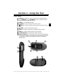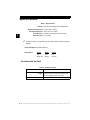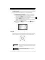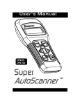
1
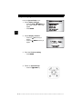
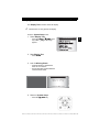
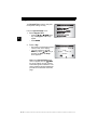
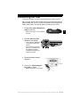
CP9449
ABS BrakeScan™
User Manual
Section 1 – Safety Precautions
For your safety, read this manual thoroughly before operating the Tool. Always
refer to and follow safety messages and test procedures provided by the
manufacturer of the vehicle or equipment being tested.
The safety messages presented below and throughout this user’s manual are
reminders to the operator to exercise care when using this test instrument.
Read All Instructions
Read, understand and follow all safety messages and instructions in this
manual and on the test equipment. Safety messages in this section of the
manual contain a signal word with a three-part message and, in some
instances, an icon.
Safety Messages
Safety messages are provided to help prevent personal injury and equipment
damage. All safety messages are introduced by a signal word. The signal word
indicates the level of the hazard in a situation. The types of safety messages
are:
!! DANGER
DANGER
Indicates a possible hazardous situation which, if
not avoided, will result in death or serious injury to
operator or bystanders.
! WARNING
Indicates a possible hazardous situation which, if
not avoided, could result in death or serious injury
to operator or bystanders.
! CAUTION
Indicates a possible hazardous situation which, if
not avoided, may result in moderate or minor injury
to operator or bystanders.
IMPORTANT
Indicates a condition which, if not avoided, may
result in damage to test equipment or vehicle.
Type Styles Used
Safety messages contain three different type styles.
• Normal type states the hazard.
• Bold type states how to avoid the hazard.
• Italic type states the possible consequences of not avoiding the hazard.
••••••••••••••••••••••••••••••••••••••••••••••••••••••••• 1–1
!
Safety Precautions
Icons Used
An icon, when present, gives a graphical description of a potential hazard.
!
Example:
Engine systems can malfunction expelling fuel, oil vapors, hot
steam, hot toxic exhaust gases, acid, refrigerant and other
debris.
Safety goggles and protective gloves must be worn by
the operator and any bystanders. Even if everyday eyeglasses have impact resistant lenses, they are NOT safety
glasses.
Engine systems that malfunction can cause injury.
Important Safety Messages
Risk of electric shock.
• Do not exceed voltage limits between inputs indicated
in the Specifications.
• Use extreme caution when working with circuits that
have voltage greater than 60 volts DC or 24 volts AC.
Electric shock can cause injury.
Risk of explosion.
! WARNING
• Safety goggles and protective clothing must be worn
by the operator and any bystanders.
- Even if everyday glasses have impact resistant lenses,
they are NOT safety glasses, and may not provide adequate protection.
• Do not use this Tool in environments where explosive
vapors may collect. These areas include:
- below-ground pits.
- confined areas.
- areas that are less than 18 inches above floor.
• If used indoors, use the Tool in locations with mechanical ventilation providing at least 4 air changes per
hour.
1–2 ••••••••••••••••••••••••••••••••••••••••••••••••••••••••
Safety Precautions
• Flammable fuel and vapors can ignite.
• Do not smoke, strike a match, or cause a spark in the
vicinity of the battery. Battery gases can ignite.
!
• Avoid making an accidental connection between the
battery terminals. Do not place anything on the battery.
• When removing battery cables, remove the ground
cable first.
• Avoid sparks when connecting or disconnecting
power leads to the battery.
• Make sure ignition is off, headlights and other accessories are off and vehicle doors are closed before disconnecting the battery cables.
- This also helps prevent damage to on-board computer
systems.
• Always disconnect the battery ground cable before
servicing electrical system components.
Explosion can cause injury.
! WARNING
Risk of poisoning.
• If used indoors, use the Tool in locations with mechanical ventilation providing at least 4 air changes per
hour. Engine exhaust contains odorless gas which can
be lethal.
• Route the exhaust outside while testing with the
engine running.
Poisoning can result in death or serious injury.
! WARNING
Battery acid is a highly corrosive sulfuric acid.
• Safety goggles and protective gloves must be worn by
the operator and any bystanders.
- Even if your everyday glasses have impact resistant
lenses, they are NOT safety glasses, and may not provide adequate protection.
• Make sure someone can hear you or is close enough
to provide aid when working near a battery.
• Have plenty of fresh water nearby.
••••••••••••••••••••••••••••••••••••••••••••••••••••••••• 1–3
Safety Precautions
- If battery acid contacts skin, clothing, or eyes, flush
exposed area with water for 10 minutes. Seek medical
help.
!
• Do not touch eyes while working near battery.
Battery acid can burn eyes and skin.
Risk of fire.
• Safety goggles and protective clothing must be worn
by the operator and any bystanders.
- Even if your everyday glasses have impact resistant
lenses, they are NOT safety glasses, and may not provide adequate protection.
• Do not position your head directly in front of or over
the throttle body.
• Do not pour gasoline down the throttle body when
cranking or running the engine, when working with
fuel delivery systems or any open fuel line.
- Engine backfire can occur when the air cleaner is out of
position.
• Do not use fuel injector cleaning solvents when performing diagnostic testing.
• Keep cigarettes, sparks, open flame and other sources
of ignition away from vehicle.
• Keep a dry chemical (Class B) fire extinguisher rated
for gasoline, chemical and electrical fires in work area.
Fire can cause death or serious injury.
Risk of flying particles.
• Safety goggles must be worn by the operator and any
bystanders while using electrical equipment.
- Electrical equipment or rotating engine parts can cause
flying particles.
- Even if your everyday glasses have impact resistant
lenses, they are NOT safety glasses, and may not provide adequate protection.
Flying particles can cause eye injury.
1–4 ••••••••••••••••••••••••••••••••••••••••••••••••••••••••
Safety Precautions
Risk of burns.
• Batteries can produce a short-circuit current
high enough to weld jewelry to metal.
- Remove jewelry such as rings, bracelets and watches
before working near batteries.
Short circuits can cause injury.
Risk of burns.
• Do not remove radiator cap unless engine is cold.
- Pressurized engine coolant may be hot.
• Do not touch hot exhaust systems, manifolds,
engines, radiators, sample probe.
• Wear insulated gloves when handling hot engine components.
• Tester leads can become hot after extended testing in
close proximity to manifolds.
Hot components can cause injury.
Risk of expelling fuel, oil vapors, hot steam, hot toxic exhaust
gases, acid, refrigerant and other debris.
• Safety goggles and protective clothing must be worn
by the operator and any bystanders.
- Even if your everyday glasses have impact resistant
lenses, they are NOT safety glasses, and may not provide adequate protection.
• Engine systems can malfunction, expelling fuel, oil
vapors, hot steam, hot toxic exhaust gases, acid,
refrigerant and other debris.
Fuel, oil vapors, hot steam, hot toxic exhaust gases, acid,
refrigerant and other debris can cause serious injury.
Engine compartment contains electrical connections and hot
or moving parts.
• Keep yourself, test leads, clothing and other objects
clear of electrical connections and hot or moving
engine parts.
••••••••••••••••••••••••••••••••••••••••••••••••••••••••• 1–5
!
Safety Precautions
• Do not wear watches, rings, or loose fitting clothing
when working in an engine compartment.
• Do not place tools or test equipment on fenders or
other places in engine compartment.
!
• Barriers are recommended to help identify danger
zones in the test area.
• Prevent personnel from walking through test area.
Contacting electrical connections and hot or moving parts can
cause injury.
Risk of injury.
• Use the Tool only as described in the user’s manual.
• Use only manufacturer’s recommended attachments.
• Do not operate the Tool with damaged cables.
• Do not operate the Tool if it has been dropped or damaged, until examined by a qualified service representative.
Operation of the Tool by anyone other than qualified personnel
may result in injury.
! CAUTION
Risk of unexpected vehicle movement.
• Block drive wheels before performing a test with the
engine running.
PRNDL2
• Unless instructed otherwise:
- Set parking brake
- Put gear selector in neutral for manual transmissions
- Put gear selector in park for automatic transmissions
- Disconnect release mechanism on the automatic parking brake release for testing and reconnect when testing
is completed.
• Do not leave a running engine unattended.
A moving vehicle can cause injury.
1–6 ••••••••••••••••••••••••••••••••••••••••••••••••••••••••
Safety Precautions
! CAUTION
Risk of equipment or circuit damage.
• Unless specifically directed by manufacturer, make
sure ignition is off before connecting or disconnecting connectors or any vehicle electrical terminals.
• Do not create a short between battery terminals with a
jumper wire or tools.
Improper equipment use can cause equipment or circuit damage.
! CAUTION
Misdiagnosis may lead to incorrect or improper repair and/or
adjustment.
• Do not rely on erratic, questionable, or obviously erroneous test information or results.
- If test information or results are erratic, question-
able, or obviously erroneous, make sure all connections and data entry information are correct
and test procedures were performed correctly.
- If test information or results are still suspicious, do
not use them for diagnosis.
Improper repair and/or adjustment may cause vehicle or
equipment damage or unsafe operation.
! DANGER
Some vehicles are equipped with air bags.
• Follow service manual warnings when working around
air bag components or wiring.
- If service manual instructions are not followed, an air
bag may deploy unexpectedly, resulting in injury.
- Note an air bag can still deploy several minutes after
ignition key is off (or even if vehicle battery is disconnected) because of a special energy reserve module.
An air bag opening can cause injury.
••••••••••••••••••••••••••••••••••••••••••••••••••••••••• 1–7
!
Section 2 – Getting Started
Introduction
ABS BrakeScan is the first tool designed for Do-It-Yourselfers to access the
ABS diagnostic information. The Tool retrieves codes from the ABS system and
provides the definition of each code to help pinpoint the problem areas within
the Antilock Brake System that may have caused the ABS light to turn on.
The Tool was developed by experts in the automotive service industry to access
the information stored in the ABS module.
All information, illustrations and specifications contained in this manual are
based on the latest information available from industry sources at the time of
publication. No warranty (expressed or implied) can be made for its accuracy
or completeness, nor is any responsibility assumed by the manufacturer or
anyone connected with it for loss or damages suffered through reliance on any
information contained in this manual or misuse of accompanying product. The
manufacturer reserves the right to make changes at any time to this manual or
accompanying product without obligation to notify any person or organization
of such changes.
ABS Overview
Anti-Lock Brake Systems (ABS) began being used on vehicles in the
mid-1980's. The mechanical components of the hydraulic-brake system
(master cylinder, shoes, pads, wheel cylinders, calipers, rotors, drums, and
assorted hardware) work the same as they did before ABS. What has changed,
however, is the addition of an ABS computer module, wheel speed sensors, and
a hydraulic control unit consisting of solenoid valves.
How ABS works
When the brake pedal is pressed with normal force, the vehicle decelerates. If,
during deceleration, the ABS computer detects wheels going at different
speeds (wheels slipping) from data provided by the wheel speed sensors, then
the vehicle enters antilock mode. During antilock mode, the ABS computer will
control brake fluid hydraulic pressure delivered to the wheels. The brake fluid
hydraulic pressure will be equal to or less than the value delivered by the master
cylinder. By controlling pressure to the wheels, the ABS computer can prevent
one wheel from locking up while others keep turning. It can also prevent wheels
from turning at different rates, so the vehicle should stop in a straight line.
ABS Configurations
ABS has had three different configurations for distribution of wheel speed
sensors and hydraulic lines from the hydraulic control unit since its conception:
• The earliest ABS configuration used one wheel speed sensor that monitor
the speed of both rear wheels. If the rear wheels would lock up, the ABS
computer would pulse a solenoid in the hydraulic control unit, which would
then change the brake fluid hydraulic pressure applied to the rear wheels.
• The next evolution in ABS added wheel speed sensors to both front
wheels, while still having a single wheel speed sensor in the rear to monitor
••••••••••••••••••••••••••••••••••••••••••••••••••••••••• 2–1
2
Getting Started
both rear wheels. Under this system, if the left front, right front, or both rear
wheels rotate at a speed different from each other, the ABS computer could
use up to three separate solenoids to control brake fluid hydraulic pressure.
This allowed the ABS system to control the left front, right front, and both
rear wheels together independently.
• Today, some vehicles have one wheel speed sensor per wheel for a total of
four. On these vehicles, the ABS computer can independently control brake
fluid hydraulic pressure on every wheel.
2
ABS Malfunction Indicator Lamp (MIL)
The dashboard or instrument panel of your vehicle contains a light labeled
something similar to ABS, or Anti-Lock, if the vehicle is ABS equipped. Some
vehicles will also have a light marked BRAKE. This light usually indicates a loss
of brake fluid hydraulic pressure or that the master cylinder is low on brake fluid.
Refer to your owner's manual for a description of the lights in your vehicle. Each
time your vehicle is started, the ABS computer performs a self-test called a
Drive Cycle during the first acceleration to make sure the ABS components are
working correctly. If the ABS computer detects a malfunction at completion of
the Drive Cycle, ABS will turn on the ABS MIL. When the ABS MIL is on, a
Diagnostic Trouble Code (DTC) is stored in the ABS computer. Once a repair
has been successfully made, the ABS computer, on most vehicles,
should turn off the ABS MIL at completion of the next Drive Cycle.
ABS Repair Tips
• Before servicing your ABS, refer to the manufacturer's recommendations.
• Torque the wheel lug nuts properly to avoid bending a rotor or drum, which
can cause inaccurate wheel speed sensor readings.
• Bleed the brake system properly.
• Always add fresh brake fluid to the master cylinder.
• Always replace tires with the manufacturer's recommended size.
• Always rotate tires as recommended by manufacturer.
• When interpreting DTCs retrieved from the vehicle, always follow the manufacturer's recommendations for repair.
! WARNING
The Tool may not detect every malfunction. Do not take
chances with brakes, steering, or other vital functions of
your vehicle, as a serious accident could result. Always
follow vehicle manufacturer’s warnings, cautions, and
service procedures.
2–2 ••••••••••••••••••••••••••••••••••••••••••••••••••••••••
Getting Started
Data Link Connector (DLC)
The Data Link Connector (DLC) is used with the Tool to communicate with the
vehicle’s control module.
2
Data Link Connector Location:
❒ Under dashboard on driver
side of vehicle.
❒ If Data Link Connector is not
located under the dashboard,
a label should be there telling
you where it is located.
Data Link Connector (DLC) Pins
1 - Manufacturer Reserved
2 - J1850 Bus+
3 - Manufacturer Reserved
4 - Chassis Ground
5 - Signal Ground
6 - CAN High, J-2284
7 - K Line, ISO 9141-2 & ISO/DIS 14230-4
8 - Manufacturer Reserved
9 - Manufacturer Reserved
10 - J1850 Bus11 - Manufacturer Reserved
1
8
9
16
12 - Manufacturer Reserved
13 - Manufacturer Reserved
14 - CAN Low, J-2284
15 - L Line, ISO 9141-2 & ISO/DIS 14230-4
16 - Battery Power
2–3 ••••••••••••••••••••••••••••••••••••••••••••••••••••••••
Section 3 – Using the Tool
The Tool
1
LCD Display - Backlit, 128 x 64 pixel display with contrast adjustment.
2
/ LEFT/RIGHT and / UP/DOWN arrow keys - Moves the cursor to
select functions or to select YES or NO.
3
ENTER key - Selects displayed items.
4
5
6
BACK key - Goes to the previous screen or level.
USER key - allows the operator to perform Read Codes with a touch of
a key.
ON/OFF - turns the tool power ON or OFF.
7
DLC Port - Provides a connection for interfacing with the vehicle.
8
USB Port - Provides a USB connection to the computer.
9
Serial Number Decal - Provides serial number of the Tool.
10 Battery Compartment - Provides power to the Tool when reprogramming
from a personal computer or for off-vehicle use such as reviewing of codes,
code lookup, and system setup. (Battery not required to use tool for
reading codes.)
4
3
1
2
7
8
6
5
9
10
••••••••••••••••••••••••••••••••••••••••••••••••••••••••• 3–1
3
Using the Tool
Specifications
Table 1: Specifications
Display: 128 x 64 pixel display with contrast adjust
Operating Temperature: 0 to 50 C (32 to 122 F)
0
0
Storage Temperature: -20 to 70 C (-4 to 158 F)
0
0
Internal Power: 9V Battery (not required to read codes)
3
External Power: 7 to 16 Volts
✓
A minimum of 8.0 V is required for most vehicle control modules to operate
properly.
Power Dissipation: 5 Watts maximum.
Dimensions:
Height
Width
Length
7/8”
3.50”
8.25”
22.56 mm
89 mm
210 mm
Included with the Tool
Table 2: Package Contents
BrakeScan Tool: Used to run diagnostics on ABS.
Vehicle Diagnostics Provides link between the vehicle and Tool
Cable: so the Tool can communicate with the vehicle. Also supplies power to the Tool.
Carry Case: Place to store the Tool when not in use.
3–2 ••••••••••••••••••••••••••••••••••••••••••••••••••••••••
Using the Tool
Display
The display has a large viewing area for posting messages, instructions, and
diagnostic information.
✓
The back-lit liquid crystal display (LCD) is a 128 x 64 pixel display.
❒ The following symbols may appear on the display. The chart below
describes what each symbol means:
Indicates that additional information is available on the previous
screen. Press the
UP arrow key to view the data.
Indicates that additional information is available on the next screen.
DOWN arrow key to view the data.
Press the
Z
Indicates that the internal battery needs replacing or is not installed.
Replace or install the internal battery.
Indicates that the
read codes.
C0023
USER key is active. Press the
USER key to
1 of 3
ABS
Left Front Whe el
Spe ed Sensor Circuit
Malfunction
Current
MIL Code
Z
Keypad
The keypad is used to move through the different menus of the Tool. The Tool’s
software is designed for easy operation with an intuitive navigation system.
! CAUTION
! CAUTION
Do not use solvents such as alcohol to clean the keypad
or display. Use a mild nonabrasive detergent and a soft
cotton cloth.
Do not soak the keypad in water because the water
might find its way inside the Tool.
••••••••••••••••••••••••••••••••••••••••••••••••••••••••• 3–3
3
Using the Tool
Tool Power Up
Power for the Tool can come from the vehicle or an internal 9V battery. All
functions work when the Tool is connected to
the car. The Review Codes, Code Lookup,
and System Setup functions will also work on
internal battery power.
Vehicle Power
3
The Tool will automatically turn on when
connected to the vehicle.
1. Attach the unit to the car.
2. Connect the Vehicle Diagnostics Cable to the Tool.
3. Connect the end of the Vehicle Diagnostics Cable to the Data Link
Connector (DLC).
✓
The Tool receives power from the vehicle when the Vehicle Diagnostics
Cable is plugged into the vehicle’s DLC
Internal Battery
ON/OFF key turns the Tool ON and OFF when operating on battery
The
power.
❒ Press and hold the
ON/OFF key for at least 1 second to turn the Tool
on or off.
✓
✓
✓
✓
✓
The Tool will automatically turn off after 2 minutes of inactivity when powered from the internal 9V battery.
When powered from the internal battery, the Tool turns off the backlighting
for the display if no key presses are made during a 1-minute period.
If a key is pressed prior to the Tool powering off,
the backlighting for the display will turn back on.
The Tool must be attached to the vehicle to perform diagnostic functions. The Tool disables the
diagnostic functions when powered from the
internal battery.
Each time the Tool is powered up, the voltage of
the internal battery is checked.
❒ If the voltage is low, the Low Battery Symbol
(Z) displays on the screen.
❒ Replace the battery using instructions provided in “Battery
Replacement
! CAUTION
If the Tool will not be used for an extended period of time,
remove the battery to prevent battery leakage from damaging
the battery compartment.
3–4 ••••••••••••••••••••••••••••••••••••••••••••••••••••••••
Using the Tool
User Key
The USER key allows you to read codes from the Diagnostic menu without
having to select Read Codes. Press the USER key to update or read codes
from the vehicle.
❒ When the
❒ When the
USER key is active, the icon appears on the display.
appears, you can perform read codes by pressing the
USER key.
USER key remains inactive until a vehicle has been selected.
❒ The
Note: The USER key is not active when the Tool is powered from the internal
9V battery.
System Setup
✓
✓
System Setup allows you to:
❒
❒
❒
❒
❒
❒
Adjust Contrast
Test the Display
Test the Keypad
Test the Memory
View Tool Information
Program the Tool
System Setup settings are retained even
if the internal battery becomes discharged or is removed.
From the Main Menu:
1. Select System Setup.
• Press the
UP or
DOWN arrow
key until System Setup is highlighted.
• Press ENTER.
MAIN MENU
=====================
Vehicle Diagnostics
Review Codes
System Setup
••••••••••••••••••••••••••••••••••••••••••••••••••••••••• 3–5
3
Using the Tool
Adjust Display Contrast
From the System Setup menu:
1. Select Adjust Contrast.
• Press the
UP or
DOWN arrow
key until Adjust Contrast is highlighted.
• Press ENTER.
SYSTEM SETUP
Adjust Contrast
3
2. Adjust Display Contrast.
• Press the
darken.
• Press the
lighten.
UP arrow key to
ADJUST CONTRAST
DOWN arrow key to
3. Save the Contrast setting.
• Press ENTER.
4. Return to System Setup.
• Press the
BACK Key.
3–6 ••••••••••••••••••••••••••••••••••••••••••••••••••••••••
Using the Tool
Display Test
The Display Test is used to check the display.
✓
The test turns on every pixel of the display.
From the System Setup menu:
1. Select Display Test.
• Press the
UP or
DOWN arrow
key until Display Test is highlighted.
SYSTEM SETUP
Display Test
2. Start Display Test.
• Press ENTER.
3. Look for Missing Pixels.
• All pixels display in solid black if
there are no concerns.
• Screen flips back and forth between
screens shown below.
Display Test
Check for missing
spots in display
Press Backto Quit
4. Return to System Setup.
• Press the
BACK Key.
••••••••••••••••••••••••••••••••••••••••••••••••••••••••• 3–7
3
Using the Tool
Keypad Test
The Keypad Test is used to verify that
the keys are working correctly.
From the System Setup menu:
SYSTEM SETUP
Keypad Test
1. Select Keypad Test.
3
• Press the
UP or
DOWN arrow
key until Keypad Test is highlighted.
• Press ENTER.
2. Press a Key.
• Key name or scroll direction should
inverse colors on the display.
• The only exception is the
BACK key. When
BACK key is
pressed, the System Setup
menu appears.
Keypad Test
=====================
ENTER
BACK
UP
LEFT RIGHT
DOWN
POWER
USER
Press BACK to Quit
Note: If the System Setup menu
does not appear, then the
BACK
key is not working correctly. Contact
Technical Support for assistance. The
phone number for Technical Support is
provided on the back side of the title
page.
3–8 ••••••••••••••••••••••••••••••••••••••••••••••••••••••••
Using the Tool
Memory Test
The Memory Test will test the tool’s internal memory. Run the Memory Test
if the Tool:
• Has trouble displaying trouble code definitions.
• Operates abnormally.
From the System Setup menu:
1. Select Memory Test.
• Press the
UP or
DOWN
arrow key until Memory Test is
highlighted.
• Press ENTER.
✓
The tool reports its progress on the
bottom of the display.
❒ The Memory Test may take
several minutes to complete.
❒ The Memory Test results display:
• If no problems were detected,
then PASS is displayed
• If RAM fails, an error message is
shown.
• If ROM fails, a checksum is
shown.
• If the Memory Test fails, contact Technical Support. The
phone number for Technical
Support is provided on the back
side of the title page.
SYSTEM SETUP
=====================
Adjust Contrast
Display Test
Keypad Test
Memory Test
Tool Information
Program Mode
Memory Test
=====================
RAM:
ROM:
EEPROM:
Pass
Pass
Pass
2. Return to System Setup.
• Press
BACK.
••••••••••••••••••••••••••••••••••••••••••••••••••••••••• 3–9
3
Using the Tool
View Tool Information
This function allows you to view specific tool information that may be needed
when contacting customer service.
From System Setup menu:
1. Select Tool Information.
3
• Press the UP or
DOWN arrow
key until Tool Information is
highlighted.
• Press ENTER.
2. View the Tool Information.
• S/N (Serial No:)
• Software ID (SW ID:)
SYSTEM SETUP
=====================
Adjust Contrast
Display Test
Keypad Test
Memory Test
Tool Information
Program Mode
Tool Information
=====================
S/N:
SWID:
1234567
A7B1
3. Write Down the Tool Information.
• Space is provided on inside front
cover of this guide to record the
Tool information.
Press BACK to Exit
4. Return to System Setup.
• Press
BACK.
Program Mode
The Program Mode is used to reprogram
the Tool. Instructions are provided with the
upgrades.
SYSTEM SETUP
=====================
Adjust Contrast
Display Test
Keypad Test
Memory Test
Tool Information
Program Mode
3 – 10 • • • • • • • • • • • • • • • • • • • • • • • • • • • • • • • • • • • • • • • • • • • • • • • • • • • • • • •
Using the Tool
Connecting the Tool
To diagnose a vehicle, connect the Vehicle Diagnostics Cable to the Tool.
Tip: If you just want to power up the tool to review codes from the last
vehicle tested, then you do not need to attach the Vehicle Diagnostics
Cable to the vehicle. The internal battery provides power for this.
1. Connect the Vehicle Diagnostics
Cable to the Tool.
• Make sure the pins on the cable are
not bent.
2. Find the Data Link Connector on the vehicle.
• Look under the dashboard
on the driver’s side of the
vehicle.
• If the Data Link Connector
(DLC) is not located under
the dashboard, a label
should be there telling you
where it is located.
3. Remove the DLC cover if
required.
4. Connect the Vehicle Diagnostics Cable to vehicle.
• Make sure the pins are not bent.
• • • • • • • • • • • • • • • • • • • • • • • • • • • • • • • • • • • • • • • • • • • • • • • • • • • • • • • • 3 – 11
3
Using the Tool
Vehicle Selection
Selecting a vehicle is required to communicate with the vehicle and to correctly
display DTC definitions. The Tool keeps all data received from the last vehicle
selected until a new vehicle is selected or the Tool is reprogrammed to update
software.
During vehicle selection, the Tool may ask for the following information:
❒
❒
❒
❒
❒
❒
❒
3
Manufacturer
Car/Truck
Year
Make
Model
Engine
Special Information
From the Main Menu:
1. Choose Vehicle Diagnostics.
• Press the UP or
DOWN arrow
key until Vehicle Diagnostics is
highlighted
• Press ENTER.
2. Select to KEEP or CHANGE
vehicle.
• To run or review diagnostics on
the same vehicle, press LEFT
for YES. Continue these instructions with Step 3.
• To run diagnostics on a different
vehicle, press
RIGHT for NO.
Continue these instructions with
Step 4.
• If this is the first time that you are
using the tool or no vehicle identification information is stored in
memory, the Tool will ask you to
provide vehicle identification information. Go to Step 5 below to
continue.
✓
MAIN MENU
=====================
Vehicle Diagnostics
Review Codes
System Setup
Confirm Selection
2002 Sunfire
2.2L
Manual Transmission
Ke ep This Vehicle?
YES
NO
The vehicle identification information is
used by the Tool to perform diagnostics. Enter or confirm vehicle identification information.
3 – 12 • • • • • • • • • • • • • • • • • • • • • • • • • • • • • • • • • • • • • • • • • • • • • • • • • • • • • • •
Using the Tool
• To erase data stored from the
previous vehicle test, press
LEFT for YES. Then go to Section 4 for instructions on running
Vehicle Diagnostics.
• To keep the existing diagnostic
data to review, press
RIGHT
for NO. Then go to Section 4 for
instructions on Reviewing
Codes.
Do You Want to
Erase Data Stored
In the Tool From
the Previous
Vehicle Tests?
3. Select to KEEP or ERASE diagnostic data.
YES
NO
3
4. Select New Vehicle?
• To erase the data stored on the
tool, press LEFT for YES. Then
go to Step 5 to enter the new
vehicle identification information.
• To keep the data stored in the
tool, press
RIGHT for NO.
Then repeat these instructions
from Step 2.
Selecting a New
Vehicle Erases Data
Stored in the Tool
From the Previous
Vehicle Tests!
Continue?
YES
NO
5. Select Vehicle Manufacturer.
• Press the UP or
DOWN arrow
key to select vehicle manufacturer.
• Press ENTER.
Select Manufacturer
====================
General Motors
Ford
Chrysler
6. Select the Vehicle Type.
• Press the UP or
DOWN arrow
key to select vehicle type.
• Press ENTER.
Select Type
====================
Car
Truck
• • • • • • • • • • • • • • • • • • • • • • • • • • • • • • • • • • • • • • • • • • • • • • • • • • • • • • • • 3 – 13
Using the Tool
7. Select the Year.
• Press the
UP or
DOWN arrow
key to select the Year.
• Press ENTER.
Select Year
====================
2005
2004
2003
2002
2001
2000
8. Select the Make.
3
✓
✓
Select Make VIN 3
====================
4=Buick
5=Cadillac
1=Chevrolet
2=Pontiac
8=Saturn
• Press the UP or
DOWN arrow
key to select the Make.
• Press ENTER.
On GM vehicles the tool may require
you to look at the VIN to determine the
Series Model, Engine Size, etc.
The following screen is for reference only.
Table 3: GM Typical VIN
VIN Position 1 2 3 4 5 6 7 8 9 10 11 12 13 14 15 16
9. Select the Model.
• Press the UP or
DOWN arrow
key to select the Model.
• Press ENTER.
10. Select the Engine.
✓
✓
• Press the
UP or
DOWN arrow
key to select the Engine.
• Press ENTER.
Model Year
Engine Type
Chassis Type
Line Chassis
Series
Make
Description of Number
Select Model
====================
Bonneville
Firebird
Formula
Grand Am
Grand Prix
Sunfire
Select Engine VIN 8
====================
ALL
If all engine types apply, the word ALL
alone will appear as shown to the right.
In some instances, the vehicle information applies to all but a few engine
sizes. In this instance, you will be given
the opportunity to choose All Others
for a size designation.
3 – 14 • • • • • • • • • • • • • • • • • • • • • • • • • • • • • • • • • • • • • • • • • • • • • • • • • • • • • • •
✓
✓
✓
Using the Tool
When provided, select the exact engine size:
❒ 4.6L
❒ 2.3L
❒ All Others
If a specific engine size is selected, you
may also need to select additional
information (called Special). If Special
information is required to identify the
ABS system, go to Step 11 to continue
these instructions.
3
If no additional information is required
to identify the ABS system, skip to Step
12 to confirm the vehicle information
selected.
11. Select Special.
• Press the UP or
DOWN arrow
key to select special information
required to identify the ABS system.
• Press ENTER.
12. Confirm Selections.
• Press
• Press
LEFT for YES.
RIGHT for NO.
Select Special
====================
Auto 4 Spe ed
Manual Transmission
Confirm Selection
2002 Sunfire
ALL
Manual Transmission
Ke ep This Vehicle?
YES
NO
✓
✓
If YES is selected, the Tool confirms
the vehicle information and then goes
to the Diagnostic Menu. See Section 4
- Vehicle Diagnostics for instructions.
If NO is selected, the Tool returns to
the Select Manufacturer screen.
Repeat these instructions from Step 5.
• • • • • • • • • • • • • • • • • • • • • • • • • • • • • • • • • • • • • • • • • • • • • • • • • • • • • • • • 3 – 15
Section 4 – Vehicle Diagnostics
ABS Diagnostic Menu
From the Diagnostic Menu, you can:
❒ Read Codes
❒ Review Codes
❒ Lookup Codes
❒ Access System Setup
DIAGNOSTIC MENU
=====================
Read Codes
Review Codes
Code Lookup
System Setup
4
1. Return to the Main Menu.
• Press the
✓
BACK key.
The Tool keeps all data received from the
last vehicle selected until any of the following occurs:
❒ Tool is reprogrammed to update
software.
❒ A new vehicle is selected.
••••••••••••••••••••••••••••••••••••••••••••••••••••••••• 4–1
Vehicle Diagnostics
Read Codes
The Read Codes function allows the Tool to read the diagnostic trouble codes
(DTCs) from the vehicle’s control modules. DTCs are used to help determine
the cause of a problem or problems with a vehicle. The anti-lock brake control
module reports DTCs pertaining to the brake system.
✓
✓
4
✓
Read Codes can be done with the key on engine off (KOEO) or with the key
on engine running (KOER).
If no DTCs are present, a message stating Pass: No Codes Found is displayed.
To access the Diagnostic Menu, select Vehicle Diagnostics from the
Main Menu and select a vehicle.
From the Diagnostic Menu:
1. Select Read Codes.
• Press the
UP or
DOWN
arrow key until Read Codes is
highlighted.
• Press ENTER.
Note: When the
by pressing the
DIAGNOSTIC MENU
=====================
Read Codes
Review Codes
Code Lookup
System Setup
symbol appears on the display, you can read codes
User key.
If an Error message displays, make sure the vehicle diagnostics cable is
attached. Turn the ignition key off for 10 seconds, then on. (This may be
required to reset the vehicle’s computer. If the problem still exists, see “Error
Messages
4–2 ••••••••••••••••••••••••••••••••••••••••••••••••••••••••
Vehicle Diagnostics
2. View diagnostic results and
write down the DTCs
Four possible results can occur:
❒ If the information returned by the
vehicle does not match the vehicle
selected, you may get an
Unexpected Results message.
• To return to the Diagnostic Menu,
press ENTER.
• To examine the selected vehicle
information stored in the tool,
press
BACK to return to the
Main Menu and then select Vehicle Diagnostics.
❒ If the tool is unable to display a
definition for all the DTCs returned by
the vehicle, you may get an
Unexpected Results - No
definitions found for some DTCs
error message.
• To view the DTCs, press ENTER.
• Press the
UP or
DOWN arrow
keys to scroll through the DTCs.
Unexpected Results
=====================
DTCs may be present
No definitions
found. Verify
selected vehicle
is correct.
Press ENTER to cont.
4
Unexpected Results
=====================
No definitions found
for some DTCs. DTCs
shown may be wrong.
Verify selected
vehicle is correct.
Press ENTER to cont.
❒ If no codes are found, a message
appears indicating that No Codes
were Found.
❒ If DTCs are found, the code and a
definition will appear. For more
information about the structure of the
DTCs, see “Understanding DTCs”
on page A-1.
• Press the
UP or
DOWN arrow
keys to scroll through the DTCs.
PASS
No Codes Found
Press BACK to cont.
3. Return to the Diagnostic Menu.
• Press the
BACK key.
Note: On most vehicles, if you successfully repair the cause of the DTC, then
the ABS MIL should turn off after the
next drive cycle completes.
••••••••••••••••••••••••••••••••••••••••••••••••••••••••• 4–3
Vehicle Diagnostics
DTC Examples
Below are several DTC examples.
DTC
Definition
DTC Status
(GM Only)
4
✓
C0023
1 of 3
ABS
Left Front Wheel
Speed Sensor Circuit
Malfunction
Current
MIL Code
Z
Number of DTCs
Vehicle Control Module
Scroll Up key
User key active
Scroll Down key
MIL Code Status
(GM Only)
General Motors provides additional information along with the DTCs:
❒ Current - A current DTC indicates that a failure is currently present. A
❒
❒
❒
❒
current code may have just occurred or may have been present over
time.
History - A DTC with a History designation is one that has been detected
by the anti-lock brake control module over a span of time. It is a current
failure that has been present long enough to be stored in long-term
memory.
CURR/HIST - A CURR/HIST DTC indicates that a failure is both current
and historical as defined above.
Intermittent - An intermittent status indicates that the DTC has appeared
intermittently since the anti-lock brake control module was reset. (Control
modules are reset by mechanics after a repair has been completed.)
MIL Code - Indicates that the ABS Computer is reporting that the ABS
Malfunction Indicator Light is on. If MIL Code is displayed by the Tool, but
the vehicle dashboard does not display the ABS MIL, then you have a
potential problem with the circuit that controls the ABS MIL, the bulb
itself, a fuse, or the electrical system.
This code indicates that you currently
have a problem with the Left Front
Wheel Speed Sensor Circuit and that
the problem is illuminating the ABS
malfunction indicator lamp (MIL) on
the dashboard.
1 of 3
ABS
C0023
Left Front Wheel
Speed Sensor Circuit
Malfunction
Current
MIL Code
Z
This code indicates that you have had
a problem with the Pump Motor Circuit
long enough to be stored in long-term
memory and that the problem is illuminating the ABS malfunction indicator
lamp (MIL) on the dashboard. ABS
systems rely on a pump to regulate
brake fluid distribution.
2 of 3
ABS
C0110
Pump Motor Circuit
History
MIL Code
4–4 ••••••••••••••••••••••••••••••••••••••••••••••••••••••••
Vehicle Diagnostics
This code indicates that you have a
current problem with the Network Bus
Communication for the ABS controller
and that the problem is illuminating the
ABS malfunction indicator lamp (MIL)
on the dashboard.
3 of 3
ABS
U2100
Controller Area
Network Bus
Communication
Current
MIL Code
Code Lookup
Code Lookup accesses a library of possible DTCs for the selected vehicle.
✓
✓
The Tool does not require power from the vehicle to perform this function.
Code Lookup is only available from the Diagnostic Menu because the
user must select a vehicle prior to accessing the library.
From the Diagnostic Menu:
1. Select Code Lookup.
UP or
DOWN
• Press the
arrow key until Code Lookup is
highlighted.
• Press ENTER.
DIAGNOSTIC MENU
======================
Read Codes
Review Codes
Code Lookup
System Setup
2. Enter a Code.
• Codes come in two formats:
OBDII and Non-OBDII. (For
more information about the possible formats, see “Understanding
DTCs” on page A-1.)
• All characters must be entered.
• Only one character can be
changed at a time.
• Use
LEFT or
RIGHT arrow
keys to move to desired character.
• Use
UP or
DOWN arrow keys
to change or select a character.
• Press ENTER.
✓
✓
C0000
Use /Arrow Keys
to Change digit.
Use / to Select
digit to change.
ENTER to Show Code.
If the definition can not be found, the
tool displays the message No Definition
Found.
Check the Service Manual for the vehicle for DTC definitions as well.
••••••••••••••••••••••••••••••••••••••••••••••••••••••••• 4–5
4
Vehicle Diagnostics
3. Enter another DTC or exit the Code Lookup function.
• Press
BACK once then repeat these instructions from Step 2.
• Press
BACK twice to return to the prior menu.
Or,
Review Codes
The Review Codes function allows the user to view the codes reported from the
previous vehicle tested.
4
✓
✓
You cannot review codes until you have run the Read Codes function. For
instructions on running the Read Codes function, see “Read Codes"
The Tool does not require power from the vehicle to use the Review Codes
function.
1. Select Review Codes.
The Review Codes function is available from both the Main Menu and
the Diagnostic Menu for your convenience.
❒ To Review Codes from the Main
Menu:
• From the Main Menu, press the
UP or
DOWN arrow key until
Review Codes is highlighted then
press ENTER.
MAIN MENU
=====================
Vehicle Diagnostics
Review Codes
System Setup
Or,
❒ To Review Codes from the
Diagnostic Menu:
• From the Main Menu, press the
UP or
DOWN arrow key until
Vehicle Diagnostics is highlighted and then press ENTER.
• From the Diagnostic Menu, use
the arrow keys to highlight
Review Codes and then press
ENTER.
DIAGNOSTIC MENU
====================
Read Codes
Review Codes
Code Lookup
System Setup
4–6 ••••••••••••••••••••••••••••••••••••••••••••••••••••••••
Vehicle Diagnostics
2. Follow prompts and instructions
provided by the Tool.
✓
✓
Refer to “Read Codes” on page 4-2 for
a description of the DTC screens.
If data does not exist, a message
informs the user to run the Read Code
function.
• To return to the prior menu, press
BACK.
No Data Stored In
Tool. Read Codes
Before Reviewing.
Press BACK
to Cont
••••••••••••••••••••••••••••••••••••••••••••••••••••••••• 4–7
4
Section 5 – Troubleshooting
Error Messages
Check the following if an error message displays:
❒ Verify ignition key is in the ON and not in the ACCESSORIES position.
❒ Make sure Vehicle Diagnostics Cable is attached to vehicle’s data link
connector (DLC) and Tool.
❒ Look at DLC and check for cracked or recessed pins, or for any
substance that could prevent a good electrical connection.
❒ Test for continuity between the DLC wiring and the vehicle computers. In
an extreme case, there may be a broken wire.
❒ Check for bent or broken pins.
❒ With the key on engine off (KOEO), check for blown fuses.
❒ Make sure the vehicle’s control module has a good ground. If the
❒
❒
computer case for the vehicle is grounded, then clean the connection
and apply a conductive (dielectric) grease to the mating surfaces.
With the KOEO, verify battery voltage is at least 8.0V.
Verify the control module is not defective. Refer to the service manual to
diagnose the control module.
Tool Does Not Power Up
Review Safety Precautions before troubleshooting. If Tool will not
power up, communicate with vehicle’s control module, pass Tool
self-tests, or functions incorrectly in any other way, do the following:
❒
❒
❒
❒
❒
Check and replace the 9V battery if needed.
Clean the DLC pins.
Disconnect and reconnect DLC making sure it is connected correctly.
Check vehicle battery to make sure at least 8.0 volts is present.
Contact customer service.
••••••••••••••••••••••••••••••••••••••••••••••••••••••••• 5–1
5
Troubleshooting
Operating Error or Erroneous Data
An Operating Error or Erroneous Data error occurs if vehicle’s computer(s)
stop(s) communicating with Tool.
1. Make Selection.
RIGHT
Operating Error
=====================
Operating error
Check Connections
Try Again?
• Press the
LEFT or
arrow key.
• Press ENTER.
Yes
No
5
Battery Replacement
The Tool requires a 9V alkaline battery to operate without vehicle power. Review
Codes, Code Lookup, and System Setup functions work on internal battery and
vehicle power. The Read Codes function works on vehicle power only.
✓
✓
✓
When the battery needs to be replaced, the low-battery icon () displays.
Rechargeable batteries do not last as long as alkaline types and are not
recommended.
Non-rechargeable Lithium (Li) battery can be used. Though Lithium types
last longer than the alkaline types, and they are more expensive.
5–2 ••••••••••••••••••••••••••••••••••••••••••••••••••••••••
Troubleshooting
1. Place Display Face Down.
• On a non-abrasive surface.
2. Remove Battery Cover.
• Turn the phillips screw counterclockwise.
• Slide battery cover off.
3. Remove Battery and Properly Discard.
5
4. Install New Battery.
• 9V Alkaline Battery.
5. Reinstall Battery Cover.
• Slide battery cover on.
• Install phillips screw turning it clockwise.
• Do not overtighten screw.
Tool Self-Tests
Tool Self-Tests check the display, keys, and internal memory.
••••••••••••••••••••••••••••••••••••••••••••••••••••••••• 5–3
ACTRON
HAND TOOLS