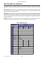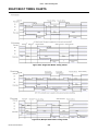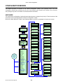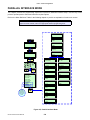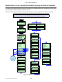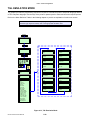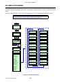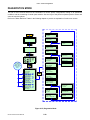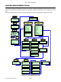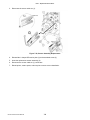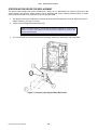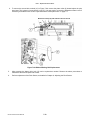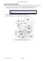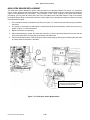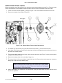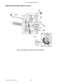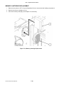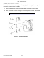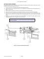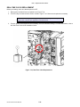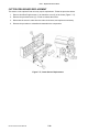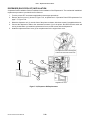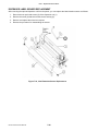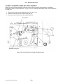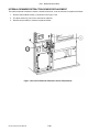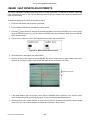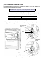
1
GL4xxe Service Manual
GL4xxe series
Read this Service Manual before and during the servicing of the
above product. Keep this document handy for future reference.
PN: 9001164
www.satoamerica.com
SATO America, Inc.
10350 Nations Ford Road
Charlotte, NC 28273
Main Phone: (704) 644-1650
Tech Support Hotline: (704)644-1660
Tech Support Fax: (704) 644-1662
Email: [email protected]
www.satoamerica.com
Be sure to ask your dealer about our maintenance contracts
to ensure peace of mind during your usage of SATO products
Version: SI-GL4xxe-01rA-06-07-07SM
© Copyright 1994 – 2007
SATO America, Inc.
Warning: This equipment complies with the requirements in Part 15 of FCC rules for a Class A
computing device. Operation of this equipment in a residential area may cause unacceptable
interference to radio and TV reception requiring the operator to take whatever steps are necessary to
correct the interference.
All rights reserved. No part of this document may be reproduced or issued to third parties in any form
whatsoever without the express permission of SATO. The materials in this document are provided for
general information and are subject to change without notice. SATO assumes no responsibilities for any
errors that may appear.
WARNING
THE EQUIPMENT REFERENCED IN THIS DOCUMENT COMPLIES WITH THE REQUIREMENTS IN PART 15
OF FCC RULES FOR A CLASS B COMPUTING DEVICE. OPERATION OF THIS EQUIPMENT IN A
RESIDENTIAL AREA MAY CAUSE UNACCEPTABLE INTERFERENCE TO RADIO AND TV RECEPTION.
TABLE OF CONTENTS
1 INTRODUCTION
About this Manual ...........................................................................................................................
General Description ........................................................................................................................
Theory of Operation ........................................................................................................................
Control Features .............................................................................................................................
2
1-2
1-3
1-4
1-5
TECHNICAL DATA ............................................................................................................. 2-1
3 INTERFACE SPECIFICATIONS
Interface Specifications...................................................................................................................
Supported Protocols .......................................................................................................................
RS232C high-speed Serial Interface ..............................................................................................
IEEE1284 Parallel Interface............................................................................................................
Universal Serial Bus (USB).............................................................................................................
Local Area Networl (LAN) Ethernet ................................................................................................
802.11G Wireless ...........................................................................................................................
All Interfaces ...................................................................................................................................
3-2
3-3
3-4
3-5
3-8
3-9
3-10
3-11
4 CHARTS AND DIAGRAMS
Print Setup Dimensions ..................................................................................................................
Label Reference Position................................................................................................................
Label adjustment diagram ..............................................................................................................
Ready/Busy timing charts ...............................................................................................................
X-ON/X-OFF timing charts..............................................................................................................
Session Connect/Disconnect diagram ............................................................................................
4-2
4-3
4-4
4-5
4-6
4-7
5 PRINTER CONFIGURATION
Printer Configuration .......................................................................................................................
Configuration Modes.......................................................................................................................
Serial Interface Mode......................................................................................................................
Parallel interface mode ...................................................................................................................
Centronics interface mode ..............................................................................................................
Uuniversal Serial Bus (USB) interface mode ..................................................................................
Local Area Network (LAN) interface mode .....................................................................................
Wireless Local Area Network (WLAN) interface mode ...................................................................
PGL emulation mode ......................................................................................................................
ZGL emulation mode ......................................................................................................................
DGL emulation mode......................................................................................................................
TGL emulation mode ......................................................................................................................
IGL emulation mode .......................................................................................................................
Diagnostics Mode ...........................................................................................................................
Printer management mode .............................................................................................................
Misc Quick Menus ..........................................................................................................................
Menu Definition Tables ...................................................................................................................
5-2
5-3
5-7
5-8
5-9
5-10
5-11
5-12
5-13
5-14
5-15
5-16
5-17
5-18
5-19
5-20
5-22
i
TABLE OF CONTENTS (cont’d)
6 TROUBLESHOOTING
Error Troubleshooting .....................................................................................................................
Troubleshooting Table ....................................................................................................................
Interface Troubleshooting ...............................................................................................................
Test Print Troubleshooting..............................................................................................................
6-2
6-8
6-10
6-12
7 REPLACEMENT PROCEDURES
Replacement Procedures ...............................................................................................................
Print Head .......................................................................................................................................
Platen Rollers .................................................................................................................................
Label Sensors.................................................................................................................................
Main PCB .......................................................................................................................................
Operational Panel PCB...................................................................................................................
Power Supply..................................................................................................................................
Stepper Motor Driver PCB ..............................................................................................................
Timing Belt......................................................................................................................................
Ribbon-Winding Belt .......................................................................................................................
Ribbon Sensor ................................................................................................................................
Head-Open Sensor.........................................................................................................................
Ribbon Boss/Torque Limiter ...........................................................................................................
Memory Cartridge ...........................................................................................................................
Interface Board ...............................................................................................................................
Cutter Kit ........................................................................................................................................
Real-Time Clock .............................................................................................................................
Cutter-Open Sensor........................................................................................................................
Dispenser Installation .....................................................................................................................
Dispenser Label Sensor .................................................................................................................
Internal Rewinder Front ..................................................................................................................
Internal Rewinder Side Cover.........................................................................................................
Internal Rewinder Retraction Base Plate ........................................................................................
Internal Rewinder Roller Driver Belt ...............................................................................................
Internal Rewinder Timing Belt.........................................................................................................
Internal Rewinder Torque Limiter ...................................................................................................
Internal Rewinder Feed Roller ........................................................................................................
Internal Rewinder Micro Sensor .....................................................................................................
Internal Rewinder Retraction Sensor..............................................................................................
Internal Rewinder Paper Load Sensor............................................................................................
7-1
7-2
7-3
7-4
7-6
7-7
7-8
7-9
7-10
7-12
7-14
7-15
7-16
7-18
7-19
7-20
7-21
7-22
7-23
7-24
7-25
7-26
7-27
7-28
7-29
7-30
7-31
7-32
7-33
7-34
ii
TABLE OF CONTENTS (cont’d)
8 CHECKING / ADJUSTMENT PROCEDURES
Performing Test Prints ....................................................................................................................
Resetting Print Head Data ..............................................................................................................
Performing Factory Test Prints .......................................................................................................
Setting the LCD Contrast................................................................................................................
Updating the Printer Firmware ........................................................................................................
I-MARK / Gap Sensor Adjustments ................................................................................................
Thermal Transfer / Direct Thermal Mode Adjustment.....................................................................
Head Open Sensor CHECKING .....................................................................................................
Print Darkness Adjustment .............................................................................................................
Pitch OFFSET Adjustments (Tear-Off/Cutter/Dispense) ................................................................
Pitch Sensor Position Adjustment...................................................................................................
Print Offset Adjustment...................................................................................................................
Print Head Alignment......................................................................................................................
Print head Pressure Setting ............................................................................................................
Print Head Pressure Balance Setting .............................................................................................
Ribbon Tension Adjustment............................................................................................................
Timing Belt Adjustments .................................................................................................................
Timing Belt Adjustments (cont’d) ....................................................................................................
Simple Dispenser Adjustment.........................................................................................................
Glossary..........................................................................................................................................
iii
8-2
8-3
8-4
8-5
8-6
8-7
8-8
8-9
8-10
8-11
8-12
8-13
8-14
8-15
8-16
8-17
8-18
8-19
8-20
8-21
This page is left blank intentionally
iv
Unit 1: Introduction
INTRODUCTION
•
•
•
•
GL4xxe Series Service Manual
About This Manual
General Description
Theory Of Operation
Operational Features
1-1
Unit 1: Introduction
ABOUT THIS MANUAL
This manual is laid out consistent with the product discussed and provides all of the information required for printer
maintenance and repair by SATO approved personnel. For the repair technician, this manual is intended to
compliment, and to be used as an extension of, owner/operator literature.
This manual also incorporates the use of special information boxes. Examples of these boxes and the type of
information provided in each, are below.
WARNING: PROVIDES INFORMATION THAT, IF UNHEEDED, MAY RESULT IN
PERSONAL INJURY.
CAUTION: PROVIDES INFORMATION THAT, IF UNHEEDED, MAY RESULT IN
EQUIPMENT DAMAGE.
ATTENTION: Provides information that is deemed of special importance but will not
result in personal injury or product damage if unheeded.
NOTE: Provides helpful hints to assist in performing the tasks at hand.
LCD screen: Provides the specific display that should be visible on the LCD at that
point.
A comprehensive Table Of Contents provided at the front of this manual facilitates rapid movement within. The
contents identify the different Units, Chapters, and some Sections. Each references the page number of their
commencement.
The pages of this manual have embedded headers and footers to assist the user in identifying his or her exact
position within the manual. The header provides the unit number followed by its name. The footer identifies the
product on the left, the page number in the center, and the manual’s part number to the right side of the page.
Page enumeration is two-part with each separated by a hyphen. The first character set references the Unit and the
second identifies the page number within that unit. Page numbers begin with the numeral one (1) at the beginning
of a new unit and ascend sequentially.
ATTENTION: The illustrations and pictures provided in this manual may display
components, assemblies, and purchase options that may not be present on individual
printers. However, where those instances arise, they are not relevant to the topic
discussed. If necessary, contact your SATO representative for updated documents
GL4xxe Series Service Manual
1-2
Unit 1: Introduction
GENERAL DESCRIPTION
SATO’s GL4xxe series printers are competitively-priced 4-inch Direct-Thermal and Thermal Transfer printers
specifically designed for low- to medium-duty manufacturing, supply-chain and retail barcode-printing and RFID
applications. The sturdy aluminium and high impact plastics ensure ruggedness in the harshest environments.
Designed from the outset to be used for RFID applications, the printer comes with all the necessary mounting,
cable routes and space considerations have been designed into the product for easy upgrading to RFID
capabilities. For high quality printing, the printer comes with fixed 203 or 305 dpi print resolutions. Users can also
alter the print resolution by purchasing a suitable print head of the desired resolution. To ensure wide compatibility,
the printer is able to handle numerous industry-standard barcode-printer languages. As well, the series comes
supplied with a wide range of interfaces such as RS232C serial, IEEE1284 high-speed parallel and USB 2.0.
Optionally, users can add 802.11g Wireless LAN and cabled LAN as options.
When connected to a network, GL printers are transformed into remote printers that are controlled by a powerful
printer management utility, SATOnet Connect™. From within a single software console, the printer administrator
can configure and control any networked GL printer even if it is located on the other side of the world.
In addition to switchable print heads, the GL4xxe series also supports options such as the Online Barcode Verifier
(OBV) can be mounted on the printer to evaluate barcode print quality and alert users of failed labels.
Right Housing Cover
Expanded Memory Cover
Left Housing Cover
Ribbon Supply Spindle
Ribbon Rewind Spindle
Media Holder
Media Guide
Ribbon Platen Roller
Ribbon Guide
Label Sensor
Rear Housing Cover
Media Platen Roller
Print Head Latch
Front Housing Cover
Upper Print Assy
Media Damper
Lower Print Assy
Figure 1-1, Primary Components
GL4xxe Series Service Manual
1-3
Unit 1: Introduction
THEORY OF OPERATION
When activated, media is fed past the print head by an integrated drive train. The drive train is electric, stepper
motor driven and coupled to a gear, pulley, and belt configuration located on the electrical side of the printer’s
center frame. A pulley is concentrically attached to the motor spindle and provides differential torque to a series of
pulleys via three timing belts. These pulleys, with gears concentrically attached, provide movement to the platen
roller spindles and provide media movement through treading contact with the roller.
Two separate stepper motors, transfer torque to the ribbon supply and ribbon rewind spindles by way of a belt
designated for each, and engaged on the opposite end, a pulley for each spindle. The pulleys located on the
printer’s electrical side, are directly attached to gears on the print side. When the ribbon spindles’ gears are
engaged with their respective pulley/gear combo, a separate gear, pulley, and belt configuration transfers torque
from the ribbon rewind spindles to ribbon rollers via a single timing belt located on the printer’s print side. The
ribbon rewind spindle rotates on axis while maintaining its projectory to takeup and rewind used ribbon.
To facilitate removal of the used ribbon material, it is wound onto a cardboard sleeve referred to as a core. The
core is inserted onto the spindle’s boss and rotates in unison. When rewinding is complete, the core is removed
along with the used ribbon material and a replacement core is inserted in its place.
Paper guides within the chassis assembly ensure the media remains properly positioned beneath the print
assembly and is fed unimpeded from the printer’s rear through to the front.
A series of strategically located sensors and switches send signals to the processing unit. Some sensors are two
part consisting of transmitting and receiving components. The transmitting component is mounted opposite of the
receiving component so that media may pass between the two. When present, the media blocks sensor
transmission from reaching the receiver. The processing unit in turn sends response signals to the various features
based on programmed and received data. These signals, are the controlling force of mechanical activities.
The print head, through thermal heat, inductively provided by electrical supply, transfers print images onto the
media as it passes. The print image may be manifested through either a direct process initiated through a chemical
reaction to the heat from within the label media or transferred from the ink coated ribbon stock.
Predetermined voltage supply of alternating current, from an independent source, is required for proper function.
The printer’s integrated power panel transforms the supplied voltage to direct current which is mediated to the
various circuitry. This circuitry is comprised of properly positioned transformers, relays, diodes, resistors, and chips
which sends, receives, and processes communication data throughout the system.
GL4xxe Series Service Manual
1-4
Unit 1: Introduction
CONTROL FEATURES
The large LCD screen and large tactile buttons allow quick operation by the operator. These functions are defined
generally here. For more specific explanations of the operational aspects, refer to the GL4xxe Operator’s Manual.
Figure 1-2, Operator Panel
GL4xxe Series Service Manual
1-5
Unit 1: Introduction
This page is left blank intentionally
GL4xxe Series Service Manual
1-6
Unit 2: Technical Data
TECHNICAL DATA
•
•
•
•
•
•
•
•
•
•
•
•
•
•
•
•
•
GL4xxe Series Service Manual
Physical Characteristics
Power
Environmental
RoHS
Processing
Command
Interface Modules
Regulatory Approvals
Print
Media
Ribbon
Sensing
Character Font Capabilities
Barcode Capabilities
Functions
Operation Panel
Accessories
2-1
Unit 2: Technical Data
PHYSICAL CHARACTERISTICS
Width
10.75 Inches (271 mm)
Height
12.00 Inches (305 mm)
Depth
18.00 Inches (455 mm)
Weight
33 Pounds (15 Kg)
ENVIRONMENTAL
Operating Temperature
41 to 104°F (5° to 40°C)
Storage Temperature
-4 to 140°F (-20° to 60°C)
Storage Humidity
15 to 85% RH Non-Condensing
Operating Humidity
15 to 85% RH Non-Condensing
POWER
Input Voltage
Consumption Voltage
100-120/200-240 Volts AC +/- 10%, 50/60 Hertz +/-5%
Maximum: 222 Volts AC, 219 Watts (when print ratio is 50%)
Standby: 22.3 Volts AC, 20.6 Watts
PROCESSING
CPU
32 Bit RISC
Flash ROM
8 Megabytes
DRAM
32 MB
COMMAND
Standard
SATO Barcode Printer Language (SBPL)
Non-Standard
N/A
INTERFACE MODULES
Enhanced Parallel Port
IEEE1284 (EPC compatible)
Serial Port
9-Pin RS232C
Universal Serial Bus (USB)
USB Adapter (480 Mbps)
Local Area Network (LAN)
10BASE-T/100BASE-TX Automatic Switching
Ethernet (Wireless LAN)
802.11g Wireless Wi-Fi
PRINT
Method
Maximum Speed (selectable)
Direct Thermal / Thermal Transfer
2, 3, 4, 5, 6, 7, 8, 9, 10 Inches Per Second (50.8 - 254 mm)
Print Module (dot size)
Resolution
.0049 Inches (.125 mm)
GL408e: 203 Dots Per Inch (8 dpmm)
GL412e: 305 Dots Per Inch (12 dpmm)
Maximum Print Width
4.09 Inches (104 mm)
Maximum Print Length
98.98 Inches (2514 mm)
GL4xxe Series Service Manual
2-2
Unit 2: Technical Data
SENSING
Gap
Position & Sensitivity Adjustable
Reflective Eye-Mark
Position & Sensitivity Adjustable
Ribbon Near End
Fixed (enabled/disabled)
Media Out
Fixed (always enabled)
Ribbon Out
Fixed (always enabled)
Cover Open
Fixed (always enabled)
MEDIA
Width
Media Width: 0.87 to 5.04 Inches (22 - 128mm)
Media Width with Backing Paper: 0.98 to 5.16 Inches (25 - 131mm)
Length (Continous)
Media Length: 0.24 to 15.63 Inches (6 - 397mm)
Media Length with Backing Paper: 0.35 to 15.75 Inches (9 - 400mm)
Length (Tear-Off)
Media Length: 0.67 to 15.63 Inches (17 - 397mm)
Media Length with Backing Paper: 0.79 to 15.75 Inches (20 - 400mm)
Type
Thickness
Roll or Fan-Fold
Eye-Mark or Gap
Direct Thermal or Thermal Transfer
0.002 to 0.010 Inches ( 0.06 - 0.268 mm)
Roll Diameter
Maximum: 10.43 Inches (265mm)
Core Diameter
1.5 to 4.0 Inches (38.1 - 101.6mm)
Wind Direction
Face In, Face Out (linerless only)
Fan-Fold Height
Maximum: 7.87 Inches (200mm)
RIBBON
Width
Maximum: 5.04 Inches (128mm)
Length
1476 Feet (450M)
Wound
Face In, Face Out
Core Diameter
1.00 Inch (25.6 mm)
Roll Diameter
Maximum: 3.35 Inches (85 mm)
REGULATORY
Radiation Noise
FCC Part 15, Subpart B, Class B
EN55022 Class B
Static Electricity
IEC61000-4-2, Level 3
AC Line Noise
Above: 1000Vp-p
Packing Drop Standard
ISTA-2A
Environmental (RoHS)
Chromium: below 0.1%
Lead: below 0.1%
Mercury: below 0.1%
Cadmium: below 0.01%
Polybrominated Bipheny (PBB): below 0.1%
Polybrominated Diphenyl Ether (PBDE): below 0.1%
GL4xxe Series Service Manual
2-3
Unit 2: Technical Data
CHARACTER FONT CAPABILITIES
MATRIX FONTS
XU
5 dots W x 9 dots H (Helvetica)
XS
17 dots W x 17 dots H (Univers Condensed Bold)
XM
24 dots W x 24 dots H (Univers Condensed Bold)
OA Font (OCR-A)
GL408e: 15 dots W x 22 dots H
GL412e: 22 dots W x 33 dots H
OB Font (OCR-B)
GL408e: 20 dots W x 24 dots H
GL412e: 30 dots W x 36 dots H
AUTO SMOOTHING FONTS
XB
48 dots W x 48 dots H (Univers Condensed Bold)
XL
48 dots W x 48 dots H (Sans Serif)
VECTOR FONT
Proportional or Fixed Spacing
Font Size 50 x 50 dots to 999 x 999 dots
Helvetica, 10 Font Variations
AGFA RASTER FONTS
A Font
CG Times, 8 to 72 pt.
B Font
CG Triumvirate, 8 to 72 pt.
DOWNLOADABLE FONTS
N/A
CHARACTER CONTROL
Expansion up to 12 x in either the X or Y coordinates.
Character Pitch Control
Line Space Control
Journal Print Facility
0, 90, 180, and 270 Degree Rotation
BARCODE CAPABILTIES
UPC A/E
JAN 8/13
EAN 8/13
Code 39
Code 93
Code 128
Interleaved 2 of 5
Industrial 2 of 5
Matrix 2 of 5
Bookland
NW-7
MSI
RSS-14
POSTNET
UCC/EAN 128
Customer Barcode
Linear Bar Codes
GL4xxe Series Service Manual
2-4
Unit 2: Technical Data
BARCODE CAPABILTIES
QR Code
Data Matrix
Maxi Code
PDF417
Micor PDF417
Synthetic Symbol
Two Dimemsional
Ratios
Bar Height
1:2, 1:3, 2:5, User definable bar widths
4 to 999 dots, User progammable
Rotation
Sequential Numbering
Expansion Ratio of Character
Graphics
Form Overlay
GL4xxe Series Service Manual
0, 90, 180, and 270 Degrees
Sequential numbering of both numerics and bar codes
Height: 1 to 12 times, Width: 1 to 12 times
Full dot addressable graphics, SATO Hex/Binary, BMP or PCX formats
Form overlay for high-speed editing of complex formats
2-5
Unit 3: Interface Specifications
INTERFACE
SPECIFICATIONS
•
•
•
•
•
•
•
•
GL4xxe Service Manual
RS232C High-Speed Serial Interface
IEEE1284 Parallel Interface
Universal Serial Bus (USB) Adapter
Local Area Network (LAN) Ethernet
802.11g Wireless
Receive Buffer (all interfaces)
ACK/NAK Protocol (all interfaces)
Status5 Return (all interfaces)
3-1
Unit 3: Interface Specifications
INTERFACE SPECIFICATIONS
This unit presents the printer interface types and their specifications. These specifications include detailed
information on the standard (built-in) and optional interfaces. An external peripheral control (EXT) interface will be
available as an optional add-on card in the near future. For further details, refer to a SATO technical
representative.
Standard Interfaces:
•
•
•
RS232C High-Speed Serial
IEEE1284 Parallel
Universal Serial Bus (USB)
Optional Interfaces:
• Local Area network (LAN) Ethernet
• 802.11g Wireless
For basic installation of interface cards, refer to the Quick Installation Guides provided with the optional interface
card. This manual supplies only highly technical data on signal interfacing.
WARNING: NEVER CONNECT OR DISCONNECT INTERFACE CABLES (OR USE
A SWITCH BOX) WITH POWER APPLIED TO EITHER THE HOST OR THE
PRINTER. THIS MAY CAUSE DAMAGE TO THE INTERFACE CIRCUITRY IN THE
PRINTER/HOST AND IS NOT COVERED BY WARRANTY.
NOTE: Some hosts monitor the Request-To-Send (RTS) signal (pin 4 of 25) to
determine if the printer is ready to receive data. Since the printer does not generate
this signal, the RTS line must be held true (high) in order to allow communication. This
can be performed by connecting the RTS pin to the Clear-To-Send (CTS) signal (pin 5
of 25).
Figure 3-1, Interface Installation
GL4xxe Service Manual
3-2
Unit 3: Interface Specifications
SUPPORTED PROTOCOLS
The SATO GL4XX can use interface and protocol listed below.
List of Protocols support
IEEE1284
Serial (9pin D-sub)
USB 2.0
CENTRONICS
LAN
WIRELESS LAN
Status 5
Status 5
Status 5
Status 5
Status 5
Status 5
Status 4
Status 4
Status 4
Status 4
Status 4
Status 4
Status 3
Status 3
Status 3
Status 3
Status 3
Status 3
Status2
Status2
Status2
Status2
Status2
Status2
Standard
Standard
Standard
Standard
Standard
Standard
Available baud rate :
600, 1200, 2400, 4800,
9600, 19200, 38400,
57600, 115200
Transfer
speed
12.5(Mbps)
Optional
Interface
Optional Interface
GL4xxe Service Manual
3-3
Unit 3: Interface Specifications
RS232C HIGH-SPEED SERIAL INTERFACE
This High Speed Serial Interface is a standard connection in the GL4xxe series printers. The serial interface circuit
characteristics are compatible with the Electronic Industry Association Specifications EIA®-232-E and EIA-422-B.
INTERFACE SPECIFICATIONS
Asynchronous ASCII
Half-duplex communication
Bi-Directional Communication
Data Transmission Rate
600, 1200, 2400, 4800, 9600, 19200, 38400, 57600 and 115200 bps
Transmission Form
Start, b1, b2, b3, b4, b5, b6, b7, b8, Stop (b8 will be omitted if using 7 bit oriented)
Data Length
7 or 8 bit (selectable)
Stop Bit
1 or 2 bit (selectable)
Parity Bit
ODD, EVEN, NONE (selectable)
Codes Used
ASC II Character Codes: 7 bits, Graphics: 8 bits
Control Codes
STX (02H), ETX (03H), ACK (06H), NAK (15H)
Connector (Printer Side)
DB-9S Male (equivalent), 9-pin Serial Interface (PCI)
Cable Connector
DB-9P Female (equivalent), 9-pin Serial Interface (PCI)
Cable Length
15 meters or less
Signal Levels
High = +5V to +12V, Low = -5V to -12V
Protocol
Ready/Busy, X-On/X-Off, Protocol for Driver, Status4, Status5
READY/BUSY INTERFACE SIGNALS
PIN
DIRECTION
SIGNAL DEFINITION
1
To Printer
Data Carrier Detect (DCD) - Status signal to the printer. The ON condition is required for the
printer to receive data
2
To Printer
Receive Data (RXD) - Serial data stream to the printer
3
To Host
Transmit Status & Control Data (TXD) - Serial data stream from the printer for transmitting
status and control information to the host. Subject to protocol selection
4
To Host
Data Terminal Ready (DTR) - Control signal from the printer. Subject to configuration.
5
Reference
Frame Ground
6
To Printer
DSR (Data Set Ready) - When this line is high, the printer will be ready to receive data. This
line must be high before data is transmitted. If this line is not being used, it should be tied high.
7
To Host
Request To Send (RTS) - Control signal from the printer. Subject to configuration
8
To Printer
Clear To Send (CTS) - Status signal to the printer indicating the host is ready to receive data/
status signals from the printer.
NOTE: Depending on the host used, it may be required to loop CS and RS
(maintaining at high-level) on the host side. For more information, refer to the host
computer documentation.
NOTE: Refer to the Chapter 4, Charts and Diagrams for Ready/Busy and X-ON/XOFF timing charts.
GL4xxe Service Manual
3-4
Unit 3: Interface Specifications
IEEE1284 PARALLEL INTERFACE
The parallel interface is a standard connection in the GL4xxe series printers. It conforms to IEEE1284
specifications. It supports three operating modes, which are determined by negotiation between the printer and the
host.
Compatibility Mode: This mode provides compatibility with Centronics-like host I/O. Data is transferred from the
host to the printer in 8-bit bytes over the data lines. Compatibility Mode can be combined with Nibble and Byte
Modes to provide bidirectional communication.
Nibble Mode: Eight bits equals one byte. When a byte of data is sent to the printer, the eight bits are sent over
eight data lines. Some devices cannot send data over their eight data lines. To bypass this, the IEEE 1284 permits
data to be sent as half a byte over four status lines. (Half a byte equals one nibble.) Two sequential four-bit nibbles
are sent over the lines. Data is transferred from printer to host in four-bit nibbles over the status lines, and the host
controls the transmission.
Byte Mode: The printer and host send data to each other along eight data lines (one bit per line). If bidirectional
communication is supported by the printer and the host, the host will take control of the data transfer.
Table of IEEE1284 signals
PIN
SOURCE
OF DATA
Type of Mode
Compatible
1
Host
nStrobe
2
Host/Printer
Data 1 (LSB)
3
Host/Printer
Data 2
4
Host/Printer
Data 3
5
Host/Printer
Data 4
6
Host/Printer
Data 5
7
Host/Printer
Data 6
8
Host/Printer
Data 7
9
Host/Printer
Data 8 (MSB)
10
Printer
11
Nibble
HostClk
Host/Clk
nAck
PtrClk
PtrClk
Printer
Busy
PtrBusy
PtrBusy
12
Printer
PError
AckDattaReq
AckDattaReq
13
Printer
Select
Xflag
Xflag
14
Host
nAutoFd
Host Busy
HostAck
15
Not defined
16
Logic Grid
17
18
19
GL4xxe Service Manual
Byte
Printer
Peripheral Logic High
Signal Ground (nStrobe)
3-5
Unit 3: Interface Specifications
Table of IEEE1284 signals
20
Signal Ground (Data 1)
21
Signal Ground (Data 2)
22
Signal Ground (Data 3)
23
Signal Ground (Data 4)
24
Signal Ground (Data 5)
25
Signal Ground (Data 6)
26
Signal Ground (Data 7)
27
Signal Ground (Data 8)
28
Signal Ground (PError, Select, nAck)
29
Signal Ground (Busy, nFault)
30
Signal Ground (nAutiFd, nSelectLn, nInit)
31
Host
nInit
32
Printer
NFault
33
Not Defined
34
Not Defined
35
Not Defined
36
Host
nSelectLn
nDataAvail
aDataAvail
1284 Active
1284 Active
1 Signals required for ieee 1284 mode. The length of the data cable from the
host computer to the printer should not exceed 32 feet (10 meters).
Host Clock / nWrite. Driven by the host. Data is transferred from the host to the printer. When the printer sends
data, two types are available. If it is Nibble Mode, the signal is set high. If it is Byte Mode, the signal is set low.
Data 1 through Data 8. These pins are host-driven in Compatibility Mode and bidirectional in Byte Mode. They are
not used in Nibble Mode. Data 1 is the least significant bit; Data 8 is the most significant bit.
Printer Clock / Peripheral Clock / Interrupt. Driven by the printer. A signal from the printer indicating the
character or function code has been received and the printer is ready for the next data transfer.
Printer Busy / Peripheral Acknowledge / nWait. Driven by the printer. Indicates the printer cannot receive data.
(Data bits 4 and 8 in Nibble Mode.)
Acknowledge Data Request / nAcknowledge Reverse. Driven by the printer. Indicates the printer is in a fault
condition. (Data bits 3 and 7 in Nibble Mode.)
Xflag. Driven by the printer. A high true level indicating the printer is ready for data transfer and the printer is
online. (Data bits 2 and 6 in Nibble Mode.)
Host Busy / Host Acknowledge / NDStrobe. Driven by the host. Activates auto-line feed mode.
Peripheral Logic High. Driven by the printer. When the line is high, the printer indicates all of its signals are in a
valid state. When the line is low, the printer indicates its power is off or its signals are in an invalid state.
nReverse Request. Driven by the host. Resets the interface and forces a return to Compatibility Mode idle phase.
GL4xxe Service Manual
3-6
Unit 3: Interface Specifications
nData Available / nPeripheral Request. Driven by the printer. Indicates the printer has encountered an error.
(Data bits 1 and 5 in Nibble Mode.) 1284 Active / nAStrobe. Driven by the host. A peripheral device is selected.
Host Logic High. Driven by the host. When set to high, the host indicates all of its signals are in a valid state.
When set to low, the host indicates its power is off or its signals are in an invalid state.
nInit. Resets init interface from the host.
GL4xxe Service Manual
3-7
Unit 3: Interface Specifications
UNIVERSAL SERIAL BUS (USB)
The Universal Serial Bus (USB) interface is a standard connection in the Gl4xxe series printers. The Universal
Serial Bus (USB) port is part of Auto Switching and is active when the Host Interface menu is set to Auto Switching
(factory default). It can also be selected as the only Host Interface under the Host Interface menu by selecting
USB.
The Host Interface menu is only available when the Admin User menu is enabled.
ATTENTION: This Interface Type Is Not Compatible With Windows 98 Or Windows
Me.
SPECIFICATIONS
Printer Connector
USB Type B Plug
Cable
10 feet (3 m) maximum
Host
Windows 2000 or above with USB Port
Power Supply
BUS Power through cable
Power Consumption
+5 V at 80 ma
A top level USB Port menu with two submenus is also available:
• Buffer Size in K - the input buffer size used by the USB port. The range is from 1 to 16. The default is 16.
• Timeout - the Hotport Timeout value used to determine when the port is inactive. The range is from 1 to 60 seconds.
The default is 10 seconds.
Program Download
Normally the Host communicates with the printer’s USB port with a Windows Driver. The Windows Driver cannot be used to
transfer binary data to the printer, such as the data contained in a Program Download. To do a Program Download through the
USB Port perform the following steps:
1. Make the printer sharable on the Host PC. This is done through the Printer Setting Window on the PC. Make note of the
Printers Shared name.
2. Open a Dos Window on the PC. At the command prompt type: NET USE LPT1\\COMP_NAME\Printers_Shared_Name /
Persistent:YES This command should be all on the same line. It redirects output on LPT1 to the shared printer.
COMP_NAME is the computer name found on the system settings. Printers_Shared_Name is the shared name found in the
printer Properties\Sharing tab.
3. To check status of connection type: Net View \\COMP_NAME
COMP_NAME is the computer name found on the system settings. Now the printer is ready.
4. Use the COPY command to send the program file to the printer. Type: COPY /b <File Name> lpt1:
5. To stop using LPT1 for USB, type: NET USE LPT1 /DELETE
GL4xxe Service Manual
3-8
Unit 3: Interface Specifications
LOCAL AREA NETWORK (LAN) ETHERNET
A Local Area Network (LAN) interface is an optional Plug-In Interface Module that can be installed by the user. It
requires a driver shipped with each printer that has the interface installed. The driver that must be loaded onto the
host computer and configured to run one of the supported network protocols using a 10Base-T or 100Base-TX
LAN connection. Details for loading the LAN driver are contained in the LAN Interface Manual that is shipped with
each printer with a LAN Optional interface installed.
SPECIFICATIONS
Connector
RJ-45 Receptacle
Cable
10/100BaseT Category 5
Cable Length
100 meters or less
Power Supply
Powered from printer
Protocol
Status3 return
Protocol for Driver (cyclic response mode)
Protocol for Driver (ENQ response mode)
Status5 return
IP Address
0.0.0.0 to 255.255.255.255
Subnet Mask
0.0.0.0 to 255.255.255.255
Gateway Address
0.0.0.0 to 255.255.255.255
SOFTWARE SPECIFICATIONS
Corresponding Protocol
TCP/IP
Network Layer
ARP, RARP, IP, ICMP
Session Layer
TCP, UDP
Application Layer
LPD, FTP, TELNET, BOOTP, DHCP
NOTE: Print data can be sent by LPR and FTP of TCP/IP and dedicated socket protocol. Printer status is obtainable by
dedicated socket protocol.
NOTE: In the TCP/IP protocol environment, LPD and FTP are provided for printing; TELNET for variable setup; ARP, RARP,
and BOOTP/DHCP for address setup.
LPD protocol complies with RFC1179 and handles the list of logical printer name as queue name such as lp, sjis, euc. In
addition, a banner page can be printed by a proper setup.
When sending the job by LPR, the transmission order of data file/control file within the job will not affect print operation. In
addition, if the banner page is specified, it will be added to each data file. Job deletion by LPR is not available.
FTP protocol complies with RFC959 and handles the list of logical printer name as a transfer directory. File transfer to this
directory executes print operation. It is possible to specify ASCII(A), Binary(I) and TENEX(L8) as transfer mode - although the
mode difference is dependent on the client. A banner page may be printed with a proper setup.
TELNET Complies with RFC854. This operation consists of interactive menu form and enables change and reference of
internal setup, and to display status. To change the setup, enter “root” user and password at the time of login. Default of root
password is set as null (linefeed only).
GL4xxe Service Manual
3-9
Unit 3: Interface Specifications
802.11G WIRELESS
The wireless print server provides easy printer interface with 802.11g Wi-Fi compliant networks free of wired
connections. Each printer is shipped with an integrated driver and interface installed. The driver must be loaded
onto the host computer and configured to run one of the supported protocols.
SPECIFICATIONS
Variable Data Rates
54, 11, 5.5, 2 and 1 Mbps
Frequency Band
2.4 GHz ISM Band
Wired Equivalent Privacy
128 bit, 40 bit (compatible with 40bit), none (WPA)
Note: Default key must match Access Point configuration. Default key is 0 for Access
Point set to use “Open System”. For 40-bit or 128-bit WEP encryption, the encryption key
must be set to the Access Point’s setting.
Authentication Method
Open, Shared, LEAP, Kerberos
Sensitivity
(typ, AAWGN, 8E-2 PER): -91dBm at 1Mbps, -88dBm at 2 Mbps, -87dBm at 5.5Mbps, 84dBm at 11Mbps.
Range
100m indoors, 300m outdoors (environmentally dependent)
Antenna Diversity
Diverse, Primary, Auxiliary
Standard Protocols
TCP/IP, IPX/SPX, Direct Mode IPX/IP, DLC/LLC, NetBEUI, NetBIOS/IP
Other Protocols
Status3 return
Protocol for Driver (cyclic response mode)
Protocol for Driver (ENQ response mode)
Status5 return
IP Address
0.0.0.0 to 255.255.255.255
Subnet Mask
0.0.0.0 to 255.255.255.255
Gateway Address
0.0.0.0 to 255.255.255.255
Communication Mode
802.11 Ad hoc, Ad hoc, Infrastructure
SSID
Optional alphanumeric character string (up to 32 characters)
Channels
01 to 15
Special Modes
International Mode: adapts to frequency requirements in Europe
GL4xxe Service Manual
3-10
Unit 3: Interface Specifications
ALL INTERFACES
RECEIVE BUFFER
The data stream is received from the host to the printer one job at a time. This allows the software program to
maintain control of the job print queue so that it can move a high priority job in front of ones of lesser importance.
A multiple job buffer allows the printer to continuously receive print jobs while compiling and printing other jobs at
the same time. It acts much like a Print buffer to maximize the performance of the host and the printer.
The printer receives and prints one job at a time. If a print job exceeds the buffer size, transmission will be rejected
by the printer. Error conditions that occur during the Print Data transmission will cause the printer to return a NAK.
ACK/NAK PROTOCOL
Bi-Directional ACK/NAK protocol is used for error control. In a normal transmission sequence when the
transmission is received, the printer will return an ACK (06H) signifying that it was received without a transmission
error. After the transmission command structure has been analyzed, a status byte is returned to the host. This
status byte informs the host of the validity of the command structure.
If the command structure is error free, the printer proceeds with the print operation. When the print operation is
completed, a Printer Status message is returned to the host. If an error was detected during the initial transmission
sequence, a NAK (15H) will be returned signalling to the host that the received transmission contained errors and
must be resent. If the returned Status byte indicates a command structure error, the error must then be corrected
before the print data is resent to the printer.
A valid transmission to the printer must be bounded by an STX/ETX pair, with the STX (02H) signifying the start of
the Print Data and ending with an ETX (03H) signifying the end.
STATUS5 RETURN
This communication protocol is designed for the purpose of monitoring and controlling print data status in the host
and featuring various functions.
INTERFACE SIGNALS
PIN
DIRECTION
SIGNAL DEFINITION
1
To Printer
DCD (Data Carrier Detect) - Status signal to the printer
2
To Host
TD (Transmit Data) - Data from the printer to the host computer.
3
To Printer
RD (Receive Data) - Data to the printer from the host computer.
5
Reference
SG (Signal Ground)
CABLE REQUIREMENTS
Depending on the host used, it may need to loop CS and RS (maintaining at high level) on the hose side. For additional
information, refer to the host computer documentation.
DB9
HOST
DIRECTION
DB9
PRINTER
1
DCD (Data Carrier Detect)
To Printer
1
DCD (Data Carrier Detect)
2
RD (Receive Data)
To Host
3
TD (Transmit Data)
3
TD (Transmit Data)
To Printer
2
RD (Receive Data)
5
SG (Signal Ground)
Bi-Directional
5
SG (Signal Ground)
GL4xxe Service Manual
3-11
Unit 3: Interface Specifications
RECEIVE BUFFER CONTROL
Causes For Receive Buffer Near Full
Receive buffer near full occurs when the remaining free space of the buffer drops to
0.95MB of 2.95MB capacity or when the remaining free space is available for storing
50 of 500 items in the history buffer.
Release Of Receive Buffer Near Full
Receive buffer near full can be released when the remaining free space rises to
1.95MB or when the remaining free space is available for storing 200 items in the
history buffer.
STATUS5 TIMING CHARTS
NORMAL PROCESS
(Figure 3-5a)
CANCEL PROCESS
(Figure 3-5b)
ERROR PROCESS
(Figure 3-5c)
GL4xxe Service Manual
3-12
Unit 3: Interface Specifications
STATUS5 TIMING CHARTS
PRINT PROCESS
(Figure 3-5d)
COMMAND PROCESS
(Figure 3-5e)
BCC ERROR PROCESS
(Figure 3-5f)
GL4xxe Service Manual
3-13
Unit 4: Charts And Diagrams
CHARTS AND DIAGRAMS
•
•
•
•
•
•
GL4xxe Service Manual
Print Setup Dimensions
Label Reference Position Diagram
Label Adjustment Diagram
Ready/Busy Timing Charts
X-On/X-Off Timing Charts
Session Connect/Disconnect Diagram
4-1
Unit 4: Charts And Diagrams
PRINT SETUP DIMENSIONS
Gap: 0.197-2.61"
Eye-Mark: 0.177-2.59"
Gap: 4.84" /
Print Width: 4.09"
Invalid Area for Print
0.118"
0.59"
Print Head
Dispenser
Figure 4-1, Print Setup Dimensions
GL4xxe Service Manual
4-2
LABEL PRINT DIRECTION
Eye-Mark: 5.08"
Gap / Eye-Mark / Paper-End
Sensors
Unit 4: Charts And Diagrams
LABEL REFERENCE POSITION
CONTINUOUS MODE
TRANSMISSION SENSOR
REFLECTIVE SENSOR
DISPENSE MODE
REFLECTIVE SENSOR
TRANSMISSION SENSOR
Base Print Position
Base Dispense Position
Base Print &
Dispense Position
Figure 4-2, Label Reference Position Diagram
GL4xxe Service Manual
4-3
LABEL PRINT DIRECTION
Base Print Position
Unit 4: Charts And Diagrams
LABEL ADJUSTMENT DIAGRAM
Figure 4-3a, Standard Position (Gap Sensor)
Figure 4-3b, Dispense Position (Gap Sensor)
GL4xxe Service Manual
4-4
Unit 4: Charts And Diagrams
READY/BUSY TIMING CHARTS
Figure 4-4a, Single-Item Buffer Timing Charts
Figure 4-4b, Multiple-Item Buffer Timing Charts
GL4xxe Service Manual
4-5
Unit 4: Charts And Diagrams
X-ON/X-OFF TIMING CHARTS
Figure 4-5a, Single-Item Buffer Timing Chart
Figure 4-5b, Multiple-Item Buffer Timing Chart
GL4xxe Service Manual
4-6
Unit 4: Charts And Diagrams
SESSION CONNECT/DISCONNECT DIAGRAM
Figure 4-6, Session connect/Disconnect Diagram
GL4xxe Service Manual
4-7
Unit 4: Charts And Diagrams
This page is left blank intentionally
GL4xxe Service Manual
4-8
Unit 5: Printer Configuration
PRINTER
CONFIGURATION
• Printer Configuration
• Configuration Modes
• Menu Definition Tables
GL4xxe Series Service Manual
5-1
Unit 5: Printer Configuration
PRINTER CONFIGURATION
This unit provides in-depth instruction on printer configuration for operation and for some troubleshooting.
The printer may be configured via the buttons and/or potentiometers located on the printer’s operator panel. All of
the printer’s buttons, switches, and potentiometers are used either singularly, or in conjunction, to perform
configuration activities.
Refer to the Control Features chapter of the Introduction unit for identification of specific interface features.
GL4xxe Series Service Manual
5-2
Unit 5: Printer Configuration
CONFIGURATION MODES
This chapter provides an overview of the various configuration modes of the operation menu. All of the
configuration activities are performed via the use of the operator panel located on the printer’s face. However,
many settings may also be controlled via external software commands.
USER MODE
This mode allows configuration of printing features that are prone to change from job to job. These are some of the
most basic and common adjustments of all of the configuration modes.
Refer to the Menu Definition Tables in the following chapter to provide an explanation of each menu screen.
Print Speed
UPC Descenders
4 ips*
Always*
Print Darkness
Vert. DPI Adjust
5*
0*
Pitch Offset
C128 Mode Switch
00.0 mm*
Manual*
Ver Print Offset
Error Handling
00.0 mm*
Beep*
POWER
ONLINE
LINE
OFFLINE
Hor Print Offset
00.0 mm*
Slew Speed Ctrl
FUNCTION
Label Length
Automatic*
152 mm*
USER MODE
Print Direction
Label Width
Head First*
104 mm*
Tear-Off Time
Slash Zero
01.0 seconds*
Disable*
Label Missing
ENTER
Character Pitch
Fault Disable*
Proportional*
USER MODE
Clip Page
Screens
only display if
Admin User is
enabled within the
Advanced
Mode
Print Speed
Print Darkness
Pitch Offset
Ver Print Offset
Hor Print Offset
Label Length
Label Width
Slash Zero
Character Pitch
Protocol C. Code
Euro Character
Ver BaseRefPoint
Hor BaseRefPoint
UPC Descenders
Vert. DPI Adjust
C128 Mode Switch
Error Handling
Mem Select (CC1)
Orientation
Slew Speed Ctrl
Print Direction
Tear-Off Time
Label Missing
Clip Page
Fault Reprint
Display Ribbon
Ribbon Near End
Units
Set Label Length
TOF Detect Fault
TOF Adjust Mode
TOF Adjust
Protocol C. Code
Enable*
Standard*
Fault Reprint
Euro Character
Enable*
213*
Display Ribbon
Ver BaseRefPoint
Enable*
0 dots*
Ribbon Near End
Hor BaseRefPoint
Enable*
0 dots*
Mem Select (CC1)
Card*
Orientation
Portrait*
Set Label Length
Manual*
TOF Detect Fault
3 labels*
TOF Adjust Mode
Units
Disable*
In Millimeters*
TOF Adjust
10.1 mm*
Figure 4-1, User Mode
GL4xxe Series Service Manual
5-3
Unit 5: Printer Configuration
CONFIGURATION MODE
The Configuration Mode is a set of menus that allows the operator to configure the printer on how to deal with
multiple print jobs. This activity is focused on loading, saving, naming those jobs, and then deleting them when no
longer needed.
Refer to the Menu Definition Tables in the following chapter to provide an explanation of each menu screen.
POWER
ONLINE
LINE
OFFLINE
FUNCTION
CONFIG MODE
CONFIG MODE
CONFIG MODE
Save Config.
Load Config.
Print Config.
Save Config.
Load Config.
Print Config.
1*
Factory*
Current*
Saving
Loading Factory
Configuration
Configuration
CONFIG MODE
CONFIG MODE
CONFIG MODE
Delete Config.
Power-Up Config.
Protect Config.
Delete Config.
Power-Up Config.
Protect Configs.
1*
Factory*
Disable*
CONFIG MODE
Config
Mode
ENTER
Deleting
Configuration
CONFIG MODE
Save Config.
Load Config.
Print Config.
Delete Config.
Power-Up Config.
Protect Config.
Name Config 1
Name Config 2
Name Config 3
Name Config 4
Name Config 5
Name Config 6
Name Config 7
Name Config 8
Reset Cfg Names
Auto Save
Name Config 1
Name Config 2
Name Config 3
1
2
3
Name Config 1
Name Config 2
Name Config 3
1*
2*
3*
Name Config 4
Name Config 5
Name Config 6
4
5
6
Name Config 4
Name Config 5
Name Config 6
4*
5*
6*
ENTER
CONFIG MODE
Name Config 7
Name Config 8
CONFIG MODE
Auto Save
7
8
Reset Cfg Names
Auto Save
Name Config 7
Name Config 8
Reset Cfg Names
Enable*
7*
8*
1*
Auto Save
Enable*
Figure 4-2, Configuration Mode
GL4xxe Series Service Manual
5-4
Unit 5: Printer Configuration
ADVANCED MODE
The Advanced Mode is provided to make basic printer operational adjustments. Typically, once these adjustments
or settings have been made, they will not require additional address unless a new job is downloaded. Use the keys
of the printer’s operator panel to select and enter the required options.
Refer to the Menu Definition Tables in the following chapter to provide an explanation of each menu screen.
POWER
Media Handling
ONLINE
Continuous*
Adv Continuous
Standard*
LINE
Print Mode
Transfer*
Please Wait
OFFLINE
Gap/Mark Sensor
Gap*
Sensed Distance
XX.X mm*
ADVANCED MODE
FUNCTION
Run Auto Cal
ADVANCED MODE
Media Profile
ADVANCED MODE
Screens
only display if
Admin User is
enabled within the
Advanced
Mode.
Run Profile
ENTER
Power Saver Time
ADVANCED MODE
ADVANCED MODE
Media Handling
Adv Continuous
Print Mode
Gap/Mark Sensor
Run Auto Cal
Run Profile
Power Saver Time
Pwr Save Control
Display Language
Alarm
Auto Online
Cancel Key
Ret. Status Port
Del Char frm F1s
Ld Char from F1s
Save Char to F1s
Del Char frm RAM
Ld Char at PwrUp
Del Set frm F1s
Ld Set from F1s
Save Set to F1s
Del Set from RAM
Ld Set at PwrUp
Main FFS
Optimize&Reboot
Print File List
Auto Locking
Set Lock Key
Max Font Buffer
Max Cache Memory
Max Cached Char
Standard Chars.
Bold Chars.
Extra Bold Char.
OCR-A Chars.
OCR-B Chars.
Tall Characters
Batch Counter
Disp. Intensity
Sensor Setup
Admin User
15 minutes*
Power Saver Time
Pwr Save Control
Enable*
Display Language
English*
Set Calendar
MM/DD/YY
hh:mm
Alarm
On*
Cancel Key
Auto Online
Enable*
Enable*
Ret. Status Port
Disable
A
ADVANCED MODE
ADVANCED MODE
Print File List
Del Char frm F1s
Ld Char from F1s
Save Char from F1s
Del Char frm RAM
Ld Char at PwrUp
Del Set frm F1s
Ld Set from F1s
Save Set to F1s
Del Set from RAM
Ld Set at PwrUp
Main FFS
Optimize&Reboot
C
D
E
F
Figure 4-3a, Advanced Mode
GL4xxe Series Service Manual
Enter to Stop
5-5
A
Unit 5: Printer Configuration
A
B
F
MAIN FFS
EMC FFS
Overwrite Files
View Main Files
Delete Files
Flash Avail.
Overwrite Files
View Main Files
Delete Files
Flash Avail.
View Main Files
View Extd Files
XXXXX.XX
XXXXX.XX
XXXXX.XX
XXXXX.XX
XXXXXX Bytes
XXXXXX Bytes
SENSOR SETUP
Sensed Distance
Sensed Distance
XX.X mm
Gap/Mark Thresh
XXX*
Paper Out Thresh
B
XXX*
D
ADVANCED MODE
SENSOR SETUP
SENSOR SETUP
SENSOR SETUP
Run Manual Cal
Pwr Up Auto-Cal
Online Auto-Cal
REMOVE MEDIA
Pwr Up Auto-Cal
Press Enter
Enable*
LOAD LINER
Head Auto-Cal
Press Enter
Enable*
LOAD MEDIA
Online Auto-Cal
Press Enter
Disable*
Max Font Buffer
Max Font Buffer
100 KBytes*
Max Cache Memory
900 KBytes*
Max Cached Char
01 KBytes*
Gap Windowing
Standard Chars.
Disable*
340*
C
Bold Chars.
Gap Length
3 mm*
ADVANCED MODE
448*
Auto Locking
Cal in Peel Mode
Extra Bold Char.
504*
Disable*
Auto Locking
Disable*
Min Calib Delta
OCR-A Chars.
384*
020*
ADVANCED MODE
Set Lock Key
Use Label Length
OCR-B Chars.
304*
Disable*
Select a new
lock key
Threshold Range
Tall Characters
50%*
Disable*
E
Mark TOF Detect
Batch Counter
ADVANCED MODE
Disable*
Disp. Intensity
Disp. Intensity
Disp. Intensity
8*
8*
F
Mark Trail Edge*
F
Figure 4-3b, Advanced Mode Continued
GL4xxe Series Service Manual
5-6
Unit 5: Printer Configuration
SERIAL INTERFACE MODE
This chapter provides the programming sequences required for RS232C and RS422 interface setup. Use the keys
of the printer’s operator panel to select and enter the required options.
Refer to the Menu Definition Tables in the following chapter to provide an explanation of each menu screen.
ATTENTION: Perform the following programming sequence only if this is the interface
type to be used. Instead, refer to the appropriate interface programming chart.
POWER
Host Interface
ENTER
ONLINE
Ignore CR/LF
Baud Rate
No*
19200*
LINE
Item No. Check
Word Length
Disable*
8*
OFFLINE
BCC Check
Stop Bits
Disable*
1*
FUNCTION
History Buffer
Parity
Temporary*
None*
INTERFACES
Comm. Protocol
Data Protocol
Status 5*
DTR*
Interface
Mode
ENTER
Buffer Size in K
16*
Trickle Time
INTERFACES
Ignore CR/LF
Item No. Check
BCC Check
History Buffer
Comm. Protocol
Host Interface
Parallel Port
USB Port
Serial Port
Printer Mgt
Host Interface
Host Interface
Serial*
Auto Switching*
1/4 sec*
Baud Rate
9600*
Timeout
Data Protocol
10 sec*
DTR*
Buffer Size in K
Disable*
16*
Serial Port
Baud Rate
Word Length
Stop Bits
Parity
Data Protocol
Buffer Size in K
Trickle Time
Time Out
Report Status
Data Term Ready
Request to Send
Poll Character
Poll Response
Idle Response
One Char Inquiry
Printer Status
Framing Errors
Screens
only display if
Admin User is
enabled within the
Advanced
Mode
Request to Send
True*
On-Line and BNF*
Parity
None*
Request to Send
Poll Character
On-Line and BNF*
00 Hex*
Poll Character
Poll Response
00 Hex*
0 ms*
Poll Response
Idle Response
0 ms*
Disable*
Idle Response
Disable*
One Char Enquiry
Trickle Time
Disable*
1/4 sec*
Printer Status
Timeout
Disable*
10 sec*
Framing Errors
Report Status
Enable*
Disable*
One Char Enquiry
Disable*
Printer Status
Disable*
Framing Errors
Enable*
Figure 4-4, Serial Interface Mode
GL4xxe Series Service Manual
Stop Bits
1*
Data Term Ready
Serial Port
ENTER
Word Length
8*
Report Status
5-7
Unit 5: Printer Configuration
PARALLEL INTERFACE MODE
This chapter provides the programming sequences required for IEEE1284 interface setup. Use the keys of the
printer’s operator panel to select and enter the required options.
Refer to the Menu Definition Tables in the following chapter to provide an explanation of each menu screen.
ATTENTION: Perform the following programming sequence only if this is the interface
type to be used. Instead, refer to the appropriate interface programming chart.
Ignore CR/LF
No*
Item No. Check
POWER
Disable*
ONLINE
BCC Check
Disable*
History Buffer
Temporary*
LINE
Comm. Protocol
OFFLINE
Status 5*
FUNCTION
INTERFACES
Interface
Mode
ENTER
INTERFACES
Ignore CR/LF
Item No. Check
BCC Check
History Buffer
Comm. Protocol
Host Interface
Parallel Port
USB Port
Serial Port
Printer Mgmt
Host Interface
Host Interface
Auto Switching*
IEEE 1284
Parallel Port
IEEE 1284
Port Type
Prime Signal
Port Type
Prime Signal
IEEE 1284*
Disable*
Buffer Size in K
TOF Action
16*
Reset*
Auto Trickle
Buffer Size in K
Disable*
16*
Trickle Time
Offset Process
1/4 sec*
Disable*
Timeout
10 sec.*
Screens
only display if
Admin User is
enabled within
the Advanced
Mode
ENTER
Report Status
Disable*
Prime Signal
Disable*
Offline Process
Disable*
Figure 4-5, Parallel Interface Mode
GL4xxe Series Service Manual
5-8
Unit 5: Printer Configuration
CENTRONICS INTERFACE MODE
This chapter provides the programming sequences required for Centronics interface setup. Use the keys of the
printer’s operator panel to select and enter the required options.
Refer to the Menu Definition Tables in the following chapter to provide an explanation of each menu screen.
ATTENTION: Perform the following programming sequence only if this is the interface
type to be used. Instead, refer to the appropriate interface programming chart.
Ignore CR/LF
No*
Item No. Check
Disable*
BCC Check
Disable*
POWER
History Buffer
ONLINE
Temporary*
Comm. Protocol
Status 5*
LINE
OFFLINE
FUNCTION
INTERFACES
Interface
Mode
ENTER
Timeout
Host Interface
Host Interface
10 sec.*
Auto Switching*
Centronics
Report Status
Parallel Port
Parallel Port
Disable*
Port Type
Port Type
Prime Signal
Port Type
CENTRONICS
Disable*
Centronics
Data Bit 8
Data Polarity
Data Bit 8
Data Bit 8
Standard*
Enable*
Enable*
Response Polarity
PI Ignored
PI Ignored
Standard*
Enable*
Enable*
Busy on Strobe
Buffer Size in K
Data Polarity
Enable*
16*
Standard*
INTERFACES
Ignore CR/LF
Item No. Check
BCC Check
History Buffer
Comm. Protocol
Host Interface
Parallel Port
USB Port
Serial Port
Printer Mgmt
Latch Data On
Auto Trickle
Resp. Polarity
10 sec*
Disable*
Standard*
Offline Process
Trickle Time
Busy on Strobe
Disable*
1/4 sec*
Enable*
Latch Data On
Screens
only display if
Admin User is
enabled within
the Advanced
Mode
ENTER
Leading*
Prime Signal
Disable*
TOF Action
Reset*
Buffer Size in K
16*
Figure 4-6, Centronics Interface Mode
GL4xxe Series Service Manual
5-9
Unit 5: Printer Configuration
UNIVERSAL SERIAL BUS (USB) INTERFACE MODE
This chapter provides the programming sequences required for USB interface setup. Use the keys of the printer’s
operator panel to select and enter the required options.
Refer to the Menu Definition Tables in the following chapter to provide an explanation of each menu screen.
ATTENTION: Perform the following programming sequence only if this is the interface
type to be used. Instead, refer to the appropriate interface programming chart.
POWER
ONLINE
LINE
OFFLINE
Ignore CR/LF
No*
FUNCTION
Item No. Check
Disable*
INTERFACES
BCC Check
Disable*
Interface
Mode
ENTER
History Buffer
Temporary*
Comm. Protocol
INTERFACES
Status 5*
Ignore CR/LF
Item No. Check
BCC Check
History Buffer
Comm. Protocol
Host Interface
Parallel Port
USB Port
Serial Port
Printer Mgmt
Ignore CR/LF
ENTER
INTERFACES
Host Interface
INTERFACES
Host Interface
Host Interface
USB Port
Auto Switching*
USB*
USB Port
Buffer Size in K
Screens
only display if
Admin User is
enabled within
Advanced
Mode
Buffer Size in K
1 to 16KB*
Timeout
10 sec*
Figure 4-7, USB Interface Mode
GL4xxe Series Service Manual
5-10
Unit 5: Printer Configuration
LOCAL AREA NETWORK (LAN) INTERFACE MODE
This chapter provides the programming sequences required for LAN interface setup. Use the keys of the printer’s
operator panel to select and enter the required options.
Refer to the Menu Definition Tables in the following chapter to provide an explanation of each menu screen.
ATTENTION: Perform the following programming sequence only if this is the interface
type to be used. Instead, refer to the appropriate interface programming chart.
POWER
ONLINE
PARL / SBPL
LINE
INTERFACES
INTERFACES
Host Interface*
Host Interface*
Host Interface
Host Interface
Auto Switching*
Ethernet*
OFFLINE
INTERFACES
ETHERNET PORT
ENTER
ETHERNET PORT
INTERFACES
Timeout
Timeout
10 sec*
Interface
Mode
ENTER
Switch Out On
Data Timeout*
INTERFACES
Ignore CR/LF
Item No. Check
BCC Check
History Buffer
Comm. Protocol
Host Interface
ETHERNET PORT
ETHERNET ADDRESS
ETHERNET SETTING
Parallel Port
USB Port
Serial Port
Printer Mgt
Screens
only display if
Admin User is
enabled within
the Advanced
Mode
INTERFACES
ETHERNET SETTING
ETHERNET SETTING
ETHERNET ADDRESS
IP Address
Subnet Mask
Gateway Address
MAC Address
DHCP
Ignore CR/LF
ENTER
NetBIOS Protocol
NetBIOS Protocol
Enable*
ASCII Data Port
IP Address
1024*
XXX.XXX.XXX.XXX
Ignore CR/LF
No*
Keep Alive Timer
Subnet Mask
3 minutes*
XXX.XXX.XXX.XXX
Item No. Check
Disable*
Ethernet Speed
Gateway Address
Auto Select*
XXX.XXX.XXX.XXX
BCC Check
Disable*
Job Control
MAC Address
Standard*
XXX.XXX.XXX.XXX
History Buffer
Temporary*
Offline Process
DHCP
Disable*
Comm. Protocol
Status 5*
Host Interface
Auto Switching*
Figure 4-8, LAN Interface Mode
GL4xxe Series Service Manual
5-11
Disable*
Unit 5: Printer Configuration
WIRELESS LOCAL AREA NETWORK (WLAN) INTERFACE MODE
This chapter provides the programming sequences required for WLAN interface setup. Use the keys of the printer’s
operator panel to select and enter the required options.
Refer to the Menu Definition Tables in the following chapter to provide an explanation of each menu screen.
ATTENTION: Perform the following programming sequence only if this is the interface
type to be used. Instead, refer to the appropriate interface programming chart.
POWER
A
ONLINE
INTERFACES
INTERFACES
Host Interface*
Host Interface*
Host Interface
Host Interface
Auto Switching*
Ethernet*
LINE
OFFLINE
C
C
ENTER
INTERFACES
ETHERNET SETTING
INTERFACES
ETHERNET SETTING
NetBIOS Protocol
Interface
Mode
ENTER
NetBIOS Protocol
Enable*
D
Screens
only display if
Admin User is
enabled within
the Advanced
Mode
INTERFACES
ASCII Data Port
Ignore CR/LF
Item No. Check
BCC Check
History Buffer
Comm. Protocol
Host Interface
ETHERNET PORT
ETHERNET SETTING
WLAN ADDRESS
WLAN SETTING
Parallel Port
USB Port
Serial Port
Printer Mgt
1024*
Keep Alive Timer
3 minutes*
A
IP Address
Subnet Mask
Gateway Address
MAC Address
DHCP
B
C
Ethernet Speed
D
E
Auto Select*
Job Control
IP Address
XXX.XXX.XXX.XXX
Subnet Mask
Standard*
XXX.XXX.XXX.XXX
Offline Process
Disable*
Gateway Address
XXX.XXX.XXX.XXX
Ignore CR/LF
No*
MAC Address
B
Item No. Check
Disable*
INTERFACES
ETHERNET PORT
BCC Check
Disable*
ETHERNET PORT
Timeout
History Buffer
Temporary*
Timeout
10 sec*
Comm. Protocol
Status 5*
Switch Out On
A
Data Timeout*
Figure 4-9, WLAN Interface Mode
GL4xxe Series Service Manual
WLAN ADDRESS
5-12
XXX.XXX.XXX.XXX
DHCP
Disable*
Unit 5: Printer Configuration
PGL EMULATION MODE
This chapter provides the programming sequences required to correlate the printer’s interpreter language with that
of Printronix interpretor language. Use the keys of the printer’s operator panel to select and enter the required
options.
Refer to the Menu Definition Tables in the following chapter to provide an explanation of each menu screen.
ATTENTION: Perform the following programming sequence only if this is the
emulation type required. Instead, refer to the appropriate emulation chart.
POWER
PGL Setup
ONLINE
LINE
OFFLINE
FUNCTION
EMULATION
Emulation
Mode
ENTER
EMULATION
Select
Select
PGL*
Character Group
Standard Sets
Select LP1
Define CR Code
Define LF Code
Autowrap
Auto Uppercase
Slash 0
Select SFCC
Host Form Length
Var Form Adjust
Var Form Type
Optimized Ratio
PI Slew Range
CR Edit
Skip Cmd Prefix
Ignore Text
Power on IGP/PGL
Ext Execute Copy
AI 00 Spaces
Select SO Char
Ignore Mode
Select Char
Do FF at TOF
Expanded Font
Scalable Size
Forms Handling
PGL Normal
UPC Descenders
I-2/5 Selection
C39 Compatibl.
User-Def Ratio
Lead PDF Dist
Trunc Dyn Data
Vertical Adjust
Error Report
Boundary Check
Repeat Form Opt
Preparser Cmd
Preparser Port
Storage Select
Character Group
Standard Sets*
Standard Sets
0) ASCII*
Select LPI
6*
Define CR Code
CR= CR*
Define LF Code
LF= LF*
Autowrap
Do FF at TOF
Disable*
Enable*
Auto Uppercase
Expanded Font
Disable*
Scalable*
Slash 0
Scalable Size
Disable*
Normal*
Select SFCC
Forms Handling
126*
Disable*
Host Form Length
PGL Normal
Enable*
LP+ Menu*
Var Form Adjust
UPC Descenders
00.0 inches*
Always*
Var Form Type
I-2/5 Selection
Add Nothing*
Loading Zero*
Optimized Ratio
C39 Compatbl.
Disable*
Disable*
PI Slew Range
User-Def Ratio
16*
Enable*
CR Edit
Lead PDF Dist
Disable*
0.10 inches*
Skip Cmd Prefix
Trunc Dyn Data
Enable*
Disable*
Ignore Text
Vertical Adjust
Disable*
0 dots*
Power on IGP/PGL
Error Report
Enable*
On*
Ext Execute Copy
Boundary Check
Disable*
Enable*
AI 00 Spaces
Repeat Form Opt
Disable*
Enable*
Select SO Char
Preparser Cmd
14*
Status*
Ignore Mode
Preparser Port
Disable*
Disable*
Select Char
Storage Select
0*
DISK= EMC*
Figure 4-10, PGL Emulation Mode
GL4xxe Series Service Manual
5-13
Unit 5: Printer Configuration
ZGL EMULATION MODE
This chapter provides the programming sequences required to correlate the printer’s interpreter language with that
of Zebra interpretor language. Use the keys of the printer’s operator panel to select and enter the required options.
Refer to the Menu Definition Tables in the following chapter to provide an explanation of each menu screen.
ATTENTION: Perform the following programming sequence only if this is the
emulation type required. Instead, refer to the appropriate emulation chart.
POWER
ONLINE
LINE
OFFLINE
FUNCTION
ZPL Compatible
Left Position
ZPL - II*
0 dots*
Command Prefix
Top Position
126*
0 dots/inch*
Label Prefix
Resolution Mode
94*
Full*
Delimiter
Vertical Adjust
44*
Enable*
Text Mode
Vertical Density
Absorb*
207 dpi*
Preparser Cmd
IS Label Fmt
HS Command*
List Format*
Preparser Port
FB Width Adjust
Disable*
0 dots*
EMULATION
Emulation
Mode
ENTER
EMULATION
Select
Select
ZGL*
ZGL Setup
ZPL Compatible
Command Prefix
Label Prefix
Delimiter
Text Mode
Preparser Cmd
Preparser Port
MC Label Fmt
PQ Label Fmt
Label Buf Size
Host Form Length
Left Position
Top Position
Resolution Mode
Vertical Adjust
Vertical Density
IS Label Fmt
FB Width Adjust
Storage Select
Network ID
Character Group
Standard Sets
MC Label Fmt
Storage Select
List Format*
B: = EMC*
PQ Label Fmt
Network ID
List Format*
0*
Label Bus Size
Character Group
560K Bytes*
Standard Set*
Host Form Length
Standard Sets
Enable*
USA 1*
Figure 4-11, ZGL Emulation Mode
GL4xxe Series Service Manual
5-14
Unit 5: Printer Configuration
DGL EMULATION MODE
This chapter provides the programming sequences required to correlate the printer’s interpreter language with that
of Datamax interpretor language. Use the keys of the printer’s operator panel to select and enter the required
options.
Refer to the Menu Definition Tables in the following chapter to provide an explanation of each menu screen.
ATTENTION: Perform the following programming sequence only if this is the
emulation type required. Instead, refer to the appropriate emulation chart.
POWER
ONLINE
LINE
OFFLINE
FUNCTION
EMULATION
Emulation
Mode
ENTER
Active
Error Handling
Yes*
Off*
Character Set
Vert. DPI Adjust
PC-8 CP 437*
0*
Euro Character
Compatibility
128*
Standard*
Control Codes
Length Cmd (STXc)
Standard*
Process*
FeedBack Chars
Heat Cmd (H)
Disable*
Process*
EMULATION
Default Module
Speed Cmd (P,S)
Select
RAM*
Process*
Select
DGL*
DGL Setup
Active
Character Set
Euro Character
Control Codes
FeedBack Chars
Default Module
Units of Measure
Row Offset
Column Offset
Format Attrib.
Error Handling
Vert. DPI Adjust
Compatibility
Length Cmd (STXc)
Heat Cmd (H)
Speed Cmd (P,S)
Cut Cmd (o,:,c)
Soft. Switch (V)
Sensor Cmd (e,r)
Format Attr. (A)
Units of Measure
Cut Cmd (o,:,c)
Imperial*
Process*
Row Offset
Soft. Switch (V)
00.00 Inch*
Process*
Column Offset
Sensor Cmd (e,r)
00.00 Inch*
Process*
Format Attrib.
Format Attr. (A)
XOR*
Process*
Figure 4-12, DGL Emulation Mode
GL4xxe Series Service Manual
5-15
Unit 5: Printer Configuration
TGL EMULATION MODE
This chapter provides the programming sequences required to correlate the printer’s interpreter language with that
of TEC interpretor language. Use the keys of the printer’s operator panel to select and enter the required options.
Refer to the Menu Definition Tables in the following chapter to provide an explanation of each menu screen.
ATTENTION: Perform the following programming sequence only if this is the
emulation type required. Instead, refer to the appropriate emulation chart.
POWER
ONLINE
LINE
OFFLINE
FUNCTION
Active
U1/U2 Move CMDs
Yes*
Process*
Print Errors
XS Sensor Param
Disable*
Process*
EMULATION
Emulation
Mode
ENTER
EMULATION
Character Set
XS Media ‘C’ Act
PC-850*
Continuous*
Slash Zero
XS Media ‘D’ Act
Disable*
Tear-Off*
Image Scale
AR Pre-Feed CMD
Disable*
Process*
Select
Select
SFCC Select
AX Fine Adj. CMD
Auto Select*
Process*
EURO Symbol
Page alignment
0xB0*
Center*
TGL*
TGL Setup
Active
Print Errors
Character Set
Slash Zero
Image Scale
SFCC Select
EURO Symbol
Speed CMDs
AY Intensity CMD
U1/U2 Move CMDs
XS Sensor Param
XS Media ‘C’ Act
XS Media ‘D’ Act
AR Pre-Feed CMD
AX Fine Adj. CMD
Page alignment
Vert. DPI Adjust
Status Response
Speed CMDs
Vert. DPI Adjust
Process*
0*
AY Intensity CMD
Status Response
Process*
Disable*
Figure 4-13, TGL Emulation Mode
GL4xxe Series Service Manual
5-16
Unit 5: Printer Configuration
IGL EMULATION MODE
This chapter provides the programming sequences required to correlate the printer’s interpreter language with that
of Intermec interpretor language. Use the keys of the printer’s operator panel to select and enter the required
options.
Refer to the Menu Definition Tables in the following chapter to provide an explanation of each menu screen.
ATTENTION: Perform the following programming sequence only if this is the
emulation type required. Instead, refer to the appropriate emulation chart.
POWER
ONLINE
LINE
IGL Setup
PwrUpMod Cmd (C)
Active*
Process*
Active
EOP Dist Cmd (D)
Yes*
Process*
OFFLINE
FUNCTION
Error Reporting
Intens. Cmd (d)
Display on LCD*
Process*
EMULATION
Emulation
Mode
ENTER
EMULATION
Mode on Power Up
TOF set Cmd (F)
Advanced 5mil*
Process*
Print Language
LRP adj. Cmd (f)
US ASCII*
Process*
IBM Translation
Speed Cmd (S)
Disable*
Process*
Select
Select
Slash Zero
Stock Cmd (T)
Font Based*
Process*
IGL*
IGL Setup
Active
Error Reporting
Mode on Power Up
Print Language
IBM Translation
Slash Zero
EURO-Symbol
Preparsing Data
Status on <ETX>
Cutter Cmd (c)
PwrUpMod Cmd (C)
EOP Dist Cmd (D)
Intens. Cmd (d)
TOF set Cmd (F)
LRP adj. Cmd (f)
Speed Cmd (S)
Stock Cmd (T)
Vert. DPI Adjust
Reported model
Saving UDCs
Save state
EURO Symbol
Vert. DPI Adjust
0x0*
0*
Preparsing data
Reported model
Disable*
Auto detect*
Status on <ETX>
Saving UDCs
Enable*
Automatic*
Cutter Cmd (c)
IGL Setup
Process*
Save state*
Figure 4-14, IGL Emulation Mode
GL4xxe Series Service Manual
5-17
Unit 5: Printer Configuration
DIAGNOSTICS MODE
This set of menu screens allows for the confirmation of various printer configurations, testing of its operational
condition, and the monitoring of certain past activities. Use the keys of the printer’s operator panel to select and
enter the required options.
Refer to the Menu Definition Tables in the following chapter to provide an explanation of each menu screen.
Priority Setting
POWER
Command*
ONLINE
Printer Tests
Checkerboard*
Test Count
5 Pages*
LINE
Software Build
XXXXXX VX.XXX
OFFLINE
Hex Dump Mode
Disable*
DIAGNOSTICS
FUNCTION
Print Error Log
DIAGNOSTICS
DIAGNOSTICS
FLASH Installed
8 Megabytes
Screens
only display if
Admin User is
enabled within the
Advanced
Mode
DIAGNOSTICS
Error Log Clear
DIAGNOSTICS
DIAGNOSTICS
Ptr On Time
XXXXX.X Hours
ENTER
DIAGNOSTICS
Printer Usage
XXXXX.X Meters
DIAGNOSTICS
PrinterHead Usage
XXXXX.X Meters
DIAGNOSTICS
Head On Time
XX.X Hours
DIAGNOSTICS
Head Type
XXX DPI
DIAGNOSTICS
Reset Head Data
DIAGNOSTICS
Resetting
Head Voltage
XX.XX +/- X.XX volts
Head Data
Figure 4-15, Diagnostics Mode
GL4xxe Series Service Manual
Clear Error Log
DRAM Installed
32 Megabytes
ENTER
Priority Setting
Printer Tests
Test Count
Software Build
Hex Dump Mode
Print Error Log
Clear Error Log
Flash Installed
DRAM Installed
Ptr On Time
Printer Usage
PrintHead Usage
Head On Time
Reset Head Data
PrintHead Usage
Head Type
Head Voltage
DIAGNOSTICS
5-18
Unit 5: Printer Configuration
PRINTER MANAGEMENT MODE
This chapter provides the programming sequences required to connect and operate the printer through a systems
network. The menu screens that will appear and will require address, is dependent on the interface type to be
used.
Refer to the Menu Definition Tables in the following chapter to provide an explanation of each menu screen.
POWER
INTERFACES
ONLINE
Printer Mgmt
Chosen:
Lan, WLAN, or Serial
ENTER
LINE
OFFLINE
FUNCTION
Chosen:
Parallel, Centronic, or USB
ENTER
Printer Mgmt
Printer Mgmt
SNC Port
Mgmt Protocol
SNC Port Number
SNC Port Timeout
Status Port Numb
Mgmt Port Number
SNC Port
Mgmt Protocol
Select Port
Baud Rate
Word Length
Stop Bits
Parity
Modem
Modem NUM
Modem Status
Dial Method
INTERFACES
SNC Port
Disable*
Serial
Ethernet
Interface
Mode
ENTER
Disable
ENTER
INTERFACES
Serial
Parallel
LAN / WLAN
Centronics
Ethernet
ENTER
Serial
ENTER
Mgmt Protocol
Mgmt Protocol
Mgmt Protocol
PXML*
PXML*
PXML*
Status Port Numb
SNC Port Number
XXXXX*
XXXXX*
Mgmt Port Number
SNC Port Timeout
XXXXX*
100 seconds*
Select Port
Status Port Numb
Debug*
Host
XXXXX*
Mgmt Port Number
XXXXX*
Host
ENTER
Debug
ENTER
Deselect Serial
Baud Rate
Modem
Mgmt Port Number
Host Interface
19200*
Disable*
XXXXX*
Word Length
Modem NUM
8*
Enable*
Stop Bits
Modem Status
1*
Enable*
Parity
Dial Method
None*
Tone*
Figure 4-16, Printer Management Mode
GL4xxe Series Service Manual
5-19
Unit 5: Printer Configuration
MISC QUICK MENUS
The flow charts in this chapter provide quick access to certain printer features without having to enter their specific
printer modes. All of the keystrokes required are performed via the printer’s operator panel.
Refer to the Menu Definition Tables in the following chapter to provide an explanation of each menu screen.
DISPLAY INTENSITY ADJUSTMENT
The keystrokes identified in Figure 4-17 provide the steps required to adjust the brightness of the printer’s LCD
without having to enter the Advanced Mode.
OFFLINE
Display Intensity
Display Intensity
Set to XX
Set to XX
OFFLINE
ENTER
Printer
saves
changes
Figure 4-17, Display Intensity Adjustment
BUFFER CLEAR
The keystrokes identified in Figure 4-18 provide the steps required to perform a Hex Dump operation without
having to enter the Diagnostics Mode.
ONLINE
CANCEL
Printer
clears
buffer
Buffer Cleared
Figure 4-18, Buffer Clear
GL4xxe Series Service Manual
5-20
Unit 5: Printer Configuration
SOFT RESET
Reboots the printer back to an online state. If the reset is performed during a parameter change, it will not be
saved. This reset will not erase any settings previously saved to non-volatile memory.
OFFLINE
+
STANDBY . . .
SOFT RESET
Printer
resets
ONLINE
Figure 4-19, Soft Reset
KEY LOCK/UNLOCK
Certain keystrokes within the printer’s menu tree is locked to prevent change under normal circumstances. These
default menu settings may be changed however, by performing the keystrokes identified in Figure 4-20.
OFFLINE
+ ENTER
ENTER SWITCH
LOCKED
+ ENTER
ENTER SWITCH
UNLOCKED
Figure 4-20, Key Lock/Unlock
GL4xxe Series Service Manual
5-21
Unit 5: Printer Configuration
MENU DEFINITION TABLES
USER MODE (TABLE 4-1)
MENU
DESCRIPTION
Permits entry into the USER Mode.
INTERFACES
Is the menu selection screen for the USER Mode.
USER MODE
Print Speed
Print Darkness
Pitch Offset
Ver Print Offset
Hor Print Offset
Label Length
Label Width
Slash Zero
Character Pitch
Protocol C. Code
Euro Character
Ver BaseRefPoint
Hor BaseRefPoint
UPC Descenders
Vert. DPI Adjust
C128 Mode Switch
Error Handling
Mem Select (CC1)
Orientation
Slew Speed Ctrl
Print Direction
Tear-Off Time
Label Missing
Clip Page
Fault Reprint
Display Ribbon
Ribbon Near End
Units
Set Label Length
TOF Detect Fault
TOF Adjust Mode
TOF Adjust
Print Speed
4 ips*
Specifies the speed in inches per second (ips) at which the media passes through the printer
while printing.
The speed may be adjusted in increments of 1 ips with a range from 1 to 10 ips.
The factory default is 4 ips.
Print Darkness
5*
Specifies the level of thermal energy provided from the print head to affect print darkness. The
print darkness setting needed is dependent on the type of ribbon and media installed for use and
also relative to print speed.
The adjustment range is from -15 to +15. The factory default is -3.
This setting vertically adjusts where the printer begins printing relative to top-of-form.
Pitch Offset
The allowable range is -12.7 to +5 millimeters.
00.0 mm*
GL4xxe Series Service Manual
5-22
Unit 5: Printer Configuration
USER MODE (TABLE 4-1)
MENU
Ver Print Offset
00.0 mm*
DESCRIPTION
Specifies the distance to advance or retract the print image on the label to determine its vertical
positioning. The actual image height is not affected by this adjustment, only its location.
The factory default is -1.00 inches with a range of 6.00 inches. A negative value (-) retracts the
image and a positive value (+) advances the image placement on the label.
Specifies the lateral distance to move the print image on the label to determine its horizontal
positioning. The actual image width is not affected by this adjustment, only its location.
Hor Print Offset
00.0 mm*
The factory default is 0.00 inches with a range from -1.00 inch to +1.00 inch. A negative value (-)
moves the image closer to the printer’s center frame and a positive value (+) moves the image
from the printer’s center frame.
Typically specifies the physical label length of the media installed. However, the type of media in
addition to its size it a determinant.
• Die-Cut Labels - the measurable length of the removable label. Does not include the liner
material or gap.
Label Length
152 mm*
• Tag Stock w/ notices or holes - the measurable length is from the trailing edge of one notch
or hole to the leading edge of the next notch or hole.
• Tag Stock w/ black marks on underside - the measurable length from the leading edge of
one black mark to the leading edge of the next black mark.
• Continuous Media w/o indicators - the measurable length depends upon the image size.
The allowable label length is from 0.1 to 0.99 inches (2.5 - 2514.6mm). The factory default is 6
inches. The label length allowable is dependent on the label’s width and the print head resolution
in use.
Label Width
Specifies the physical width of the print image. The allowable range is 0.1 to 4.1 inches (2.5 104mm).
104 mm*
Determines if a zero is printed with or without a diagonal slash through it.
Slash Zero
Disable*
Character Pitch
Proportional*
Protocol C. Code
This setting determines whether each printer character occupies a designated space (Fixed)
regardless of the character’s width, or if the character’s space is representative of its width
(Proportional).
Proportional is contemporarily preferred.
The ESC sequence in SBPL commands may be defined as standard (using non-printable code
1BH) or non-standard (Hex 5E).
Standard*
Changes the address of the Euro character.
Euro Character
213*
GL4xxe Series Service Manual
5-23
Unit 5: Printer Configuration
USER MODE (TABLE 4-1)
MENU
Ver BaseRefPoint
DESCRIPTION
This setting changes the vertical base reference point for the current label job and all subsequent
label jobs. Its effect is identical to the <ESC>A3 Base Reference Point command.
0 dots*
Hor BaseRefPoint
This setting changes the horizontal base reference point for the current label job and all
subsequent label jobs. Its effect is identical to the <ESC>A3 Base Reference Point command.
0 dots*
This parameter allows the printing of bar code descenders when human readable data is not
presented in the UPC/EAN barcodes.
UPC Descenders
• No Change - factory default.
Always*
• Always - factory default. UPC/EAN bar codes are printed with descenders even if human
readable data is not present.
• Never - UPC/EAN bar codes are printed without descenders.
Vert. DPI Adjust
0*
C128 Mode Switch
Allows fine adjustment of resolution used to scale page elements/coordinates. In cases where the
printed label length is incorrect, the vertical resolution value used for calculations can be fine
adjusted by this menu between -100 and +100.
Negative values result in a lower DPI value and thusly a longer label. Positive values result in a
higher DPI value resulting in a shorter label. This adjustment does not affect the size of images
and downloaded bitmap fonts.
Allows compatibility with older SATO printer models. By selecting ‘Automatic’ enables the printer
to encode C128 bar code data using automatic mode switching. This action generally results in
smaller barcodes.
Manual*
Error Handling
If enabled, the printer will beep if an invalid code is deleted in the format file being downloaded/
printed.
Beep*
Specifies the memory assigned to parameters 1 and 2 of <ESC>CC command.
Mem Select (CC1)
Card*
If the operator panel selection is set to Card, the command <ESC>CC1 declares that the memory
cartridge is to be used to recall/store data (graphic & font) and CC2 is to be used to access
internal flash memory.
If the operator panel selection is to Memory, the above scenario is reversed.
This menu screen allows the image orientation on the printed label to be determined.
• Portrait - specifies vertical page orientation with page height being greater than its width.
The top-right corner of the image is positioned in the media’s leading right corner.
Orientation
Portrait*
• Landscape - specifies horizontal orientation with page width being greater than its height.
The top-left corner of the image is positioned in the media’s leading left corner.
• Inv. Portrait - specifies vertical page orientation with page height being greater than its width.
The bottom-right corner of the image is positioned in the media’s trailing left corner.
• Inv. Landscape - specifies horizontal orientation with page width being greater than its
height. The top-right corner of the image is positioned in the media’s trailing right corner.
GL4xxe Series Service Manual
5-24
Unit 5: Printer Configuration
USER MODE (TABLE 4-1)
MENU
DESCRIPTION
Allows selection of the manner of determining the speed of media movement during non-print
activity.
Slew Speed Ctrl
• Automatic - always the same as the print speed.
Automatic*
• Manual - allows the slew speed to be set. Selecting this option brings up another menu that
allows a speed range from 2 to 10 ips. The factory default is 6 ips, but the maximum slew
speed is also determined by the printer model.
Determines basic print image orientation.
Print Direction
Head First*
• Head First - the edge of the image that has been determined to be the top will be printed
first. In the case of a portrait, the head will print and exit the printer first.
• Foot First - the edge of the image that has been determined to be the bottom will be printed
first. In the case of a portrait, the head will be printed and exit the printer last.
Note: This feature will not change the orientation of any test patterns in the DIAGNOSTIC mode.
Tear-Off Time
01.0 seconds*
Allows specification of the number of seconds after the buffer is empty that the printer will wait
before it advances media to the tear bar position. This is applicable when Media Handling is set
to Tear-Off Strip or Continuous mode and Continuous mode is set Tear-strip Full.
The allowed range is .1 to 60.0 seconds and the factory default is 1.0 seconds.
Allows a label to be detected at the tear bar for the Peel-Off Media mode.
Label Missing
Fault Disable*
• Fault Disable - factory default. The printer does not generate a fault condition if a missing
label is encountered.
• Fault Enable - the printer generates a fault condition if a missing label is encountered.
Determines how the printer handles images that are too large for one physical page length when
using gap or black mark media.
• Enable - factory default. When the user selected page length is greater than the physical
page length, the printer clips the excess data to fit the physical page and the excess data is
lost. The media sensor consequently looks for the gap, notch, hole, or black mark and when
detected, uses it as the top-of-form position for the next label. Any remaining data is clipped
from the label being printed.
Clip Page
Enable*
• Disable - when the user selected page length is greater than the physical page length
dictated by the gap, notch, hole, or black mark on media, the printer continues to print the
remaining excess data onto the next physical page. The media sensor looks for the gap,
notch, hole, or black mark only after the media has advanced the distance specified by the
label length value in the Media Setup menu or by the Host Forms Length value sent by via
the software. Any gaps, notches, holes, or black marks that exist prior to reaching the Label
Length or Host Forms Length are ignored.
Note: When Disable is selected, media sensing reliability can be improved, but the correct label
length value must be entered. If the value is too long, the printer will ignore the actual gap or mark
it needs to detect. When gap sensing is used, the Label Length value is equal to the physical
length of a die-cut or removable label. When eye-mark sensing is used, the Label Length value is
the physical distance from the leading edge of one eye-mark to the leading edge of the next.
Fault Reprint
Enable*
This menu option determines how the printer handles data that was printing when an error
occurred.
• Disable - factory default. Will not reprint a label affected by an error condition.
• Enable - Will reprint a label affected by an error condition.
Display Ribbon
Enable*
When enabled and the printer is online, 1 to 4 asterisks will display on the LCD indicating the
approximate amount of ribbon remaining on the supply spindle.
**** = full to 3/4 full, *** = 1/2 to 3/4 full, ** = 1/4 to 1/2 full, * = 1/8 to 1/4 full.
Enable is the factory default.
GL4xxe Series Service Manual
5-25
Unit 5: Printer Configuration
USER MODE (TABLE 4-1)
MENU
Ribbon Near End
Enable*
DESCRIPTION
When enabled and the amount of ribbon remaining on the supply spindle is approximately 75 to
50 meters or less, the ON LINE indicator of the operator panel will flash and ‘Ribbon Low’ will
display on the second line of the LCD. The warning message will not prevent printing.
The Display Ribbon option must be enabled for the warning to display. Disable is the factory
default setting.
This menu screen allows selection of millimeters or inches as the unit of measure.
Inches is the factory default.
Units
In Millimeters*
Allows selection of whether the Sensed Distance value derived from an Auto or Manual Calibrate
will be used to set the Label Length value in the Media Setup menu.
• Manual - factory default. The Sensed Distance value derived from an Auto or Manual
Calibrate will not override or change the Label Length value.
Set Label Length
Manual*
• Automatic - when an Auto or Manual Calibrate is performed, the Sensed Distance value
derived from either calibration will override and change the Label Length value. If Auto or
Calibrate is not performed, the current Label Length value will be used.
Note: When Set Label Length = Automatic and the label sensor is set to Gap, the printer will
subtract the Gap Length value (in the Sensor Setup menu of the Advanced Mode) from the
Sensed Distance value obtained when the Auto or Manual Calibrate was performed. Setting the
label length to ‘Automatic’ sets the ‘Use Label Length’ menu to ‘Disable’ in the Sensor Setup
menu of the Advanced Mode.
TOF Detect Fault
3 labels*
Allows selection of top-of-form detection fault. The printer displays a ‘Gap Not Detected’ fault and
stops printing when media has advanced a distance equal to the selected quantity or more times
the Label Length value set in menu.
• 3 Labels - factory default.
• 9 Labels
• 1 Label
Allows the top-of-form distance to be set using the TOF Adjust menu.
TOF Adjust Mode
• Enable - enables the adjustment through the TOF Adjust menu.
Disable*
• Disable - factory default. Disables the adjustment through the TOF Adjust menu.
TOF Adjust
10.1 mm*
This option sets the distance from the top-of-form (TOF) that is left blank (unprinted) after a label
has been removed in Tear-Off Strip. Printing normally starts at top-of-form, but when enabled, the
print start position can be adjusted from 0.00 to 0.40 inches from top-of-form in increments of
0.01 inches.
This adjustment is useful if a die-cut label sticks to the platen because of jagged edges created
by poor label removal using the tear bar. By controlling how much blank space there is from topof-form, the amount of media called back after being torn off can be controlled.
CONFIGURATION MODE (TABLE 4-2)
MENU
DESCRIPTION
Permits entry into the CONFIGURATION Mode.
CONFIG MODE
GL4xxe Series Service Manual
5-26
Unit 5: Printer Configuration
CONFIGURATION MODE (TABLE 4-2)
MENU
DESCRIPTION
Is the menu selection screen for the CONFIGURATION Mode.
CONFIG MODE
Save Config.
Load Config.
Print Config.
Delete Config.
Power-Up Config.
Protect Config.
Name Config 1
Name Config 2
Name Config 3
Name Config 4
Name Config 5
Name Config 6
Name Config 7
Name Config 8
Reset Cfg Names
Auto Save
CONFIG MODE
Save Config.
This menu allows up to eight unique configurations to be saved to meet different printer
requirements. These saved configurations eliminate the need to change the parameter settings
as needed. The configurations are stored in memory and will not be lost when the printer is
powered off.
Note: If the Protect Configs feature is enabled, the new configuration will not be saved unless the
existing configuration has first been deleted.
The factory default is 1.
Save Config.
Is a sub-menu of the configuration save feature. This menu screen permits a particular print job to
be assigned a numeral reference. As many as eight printer configurations may be saved.
1*
Is an informational menu screen displaying the configuration is being saved.
Saving
Configuration
CONFIG MODE
The printer can store up to eight configurations in memory. This menu set allows the selection
and loading of a specific configuration.
Load Config.
Load Config.
Factory*
Is a sub-menu of the configuration load feature. This menu screen permits a particular
configuration to be assigned a numeral reference. As many as eight configurations may be
loaded.
The factory default is Factory.
Is an informational menu screen displaying the configuration is being loaded.
Loading Factory
Configuration
GL4xxe Series Service Manual
5-27
Unit 5: Printer Configuration
CONFIGURATION MODE (TABLE 4-2)
MENU
CONFIG MODE
DESCRIPTION
This menu set is used to print a list of various stored printer configurations. It is recommended
that a printed list of loaded/saved configurations be kept for quick reference.
Print Config.
Is a sub-menu of the configuration print feature.
Print Config.
The factory default is Current.
Current*
This menu set is used to delete specific configurations stored in the printer’s memory.
CONFIG MODE
Delete Config.
Allows the selection of the configuration to be deleted. The factory default may not be deleted.
Delete Config.
The factory default is 1.
1*
Is an informational menu screen displaying the configuration is being deleted.
Deleting
Configuration
CONFIG MODE
Power-Up Config.
This menu set allows the selection of which stored configuration will be initialized when the printer
is powered on. Any one of the saved configurations or the factory default configuration may be
chosen.
The factory default is Factory.
Allows the selection of the configuration that will be initialized at startup.
Power-Up Config.
Factory*
This menu set determines if a new configuration will overwrite an existing configuration.
CONFIG MODE
Protect Config.
Allows the selection of the desired option.
Protect Configs.
• Disable - factory default. Will overwrite.
Disable*
• Enable - will not overwrite.
Name Config 1
1
GL4xxe Series Service Manual
There is a menu set for each of the saved configurations (1 through 8). By entering the specific
menu set designated for a particular configuration, that configuration may be provided with a text
name. The assigned text name may not exceed 15 characters.
When a configuration has been assigned a name here, all other menus (Save, Load, Print,
Delete, Power-Up, Protect) relative to that particular configuration will also display the assigned
file name.
5-28
Unit 5: Printer Configuration
CONFIGURATION MODE (TABLE 4-2)
MENU
Name Config 1
DESCRIPTION
This menu screen permits the designation of the desired file name. Use the arrow keys of the
printer’s operator panel to scroll and select appropriate characters in the appropriate sequence.
1*
CONFIG MODE
This menu set permits file names for print configurations to be reset to their respective default
configuration number. Either a particular file may reset or all.
Reset Cfg Names
The available options for file name reset is 1, 2, 3, 4, 5, 6, 7, 8, or All. The factory default is 1.
Reset Cfg Names
1*
CONFIG MODE
This menu set allows selection of whether the printer will automatically prompt the operator to
save alterations made to any of the stored configurations.
Auto Save
Allows selection of the desired menu option.
• Enable - factory default. Will prompt.
Auto Save
Enable*
• Disable - will not prompt.
Note: If currently in the Factory Config menus and a change is made, pressing ENTER saves to
Config 1 or the next available configuration set and becomes the Power-Up Config.
If the Current Config is configuration set 1 and a change is made, pressing ENTER will save the
change to Config 1.
ADVANCED MODE (TABLE 4-3)
MENU
DESCRIPTION
Permits entry into the ADVANCED Mode.
ADVANCED MODE
GL4xxe Series Service Manual
5-29
Unit 5: Printer Configuration
ADVANCED MODE (TABLE 4-3)
MENU
ADVANCED MODE
DESCRIPTION
Is the premiere menu screen of the Advanced Mode. Allows scrolling and selection of its primary
menu options.
Media Handling
Adv Continuous
Print Mode
Gap/Mark Sensor
Run Auto Cal
Run Profile
Power Saver Time
Pwr Save Control
Display Language
Alarm
Auto Online
Cancel Key
Ret. Status Port
Del Char frm F1s
Ld Char from F1s
Save Char to F1s
Del Char frm RAM
Ld Char at PwrUp
Del Set frm F1s
Ld Set from F1s
Save Set to F1s
Del Set from RAM
Ld Set at PwrUp
Main FFS
Optimize&Reboot
Print File List
Auto Locking
Set Lock Key
Max Font Buffer
Max Cache Memory
Max Cached Char
Standard Chars.
Bold Chars.
Extra Bold Char.
OCR-A Chars.
OCR-B Chars.
Tall Characters
Batch Counter
Disp. Intensity
Sensor Setup
Admin User
Permits selection of the media handling method desired.
• Tear-Off - factory default. Prints labels until the print buffer is empty, then positions the last
label over the tear bar for removal.
• Continuous - prints continuously and feeds the printed labels along with its backing paper.
Media Handling
Continuous*
• Peel-Off - prints die-cut labels and automatically peels away the backing paper as each label
advances from the printer. The printer waits until the printed label is taken for application
before printing the next label. This method is only supported when the Value Peel or the
Peel-Off Rewinder option is installed. A Remove Label message will display on the LCD
prompting label removal for each label printed.
• Cut - cuts printed labels or tags at the user specified intervals. Cutting may occur after each
printed label/tag or following a specified quantity. Only available with cutter assembly
installed.
• Rewind - rewinds printed labels onto a spindle assembly. This option is used for efficient
storage of the printed labels to be applied at a later date. Only available with rewinder
assembly installed.
GL4xxe Series Service Manual
5-30
Unit 5: Printer Configuration
ADVANCED MODE (TABLE 4-3)
MENU
DESCRIPTION
Allows selection of special media modes when the Continuous option is chosen as the Media
Handling method.
• Standard - factory default. Printing occurs without automatic media offset or positioning for
each consecutive label. In such applications, the FEED key may need to be pressed to
position the next label for printing. Will result in a blank label being fed between each printed
label to advance the media sufficiently to remove the printed label.
Adv Continuous
Standard*
• Tear-Off - provides offset movement of the media to position the perforated line of its
backing paper at the tear bar. This option will not result in blank labels as with the Standard
method, but only supports label lengths 2.50 inches or longer.
• Tear-Strip Full - provides offset movement of the media to position the perforated line of its
backing paper at the tear bar once the print buffer is empty for a period Test Strip Time
(media is not aligned at the tear bar until that time expires). when printable data is again
detected, a blank label is automatically fed resulting in one blank label between each print
job. This option supports label lengths 2.50 inches or longer. Shorter label lengths will result
in two or more blank labels to be automatically fed at the beginning of each print job.
This option specifies the media type to be used.
Print Mode
• Transfer - factory default. Indicates thermal transfer media requiring ribbon stock.
Transfer*
• Direct - indicates direct thermal printing using heat sensitive media without ribbon stock.
Allows specification of the label sensor to be used relative to the media type for label length
indication (gap, notch, hole, eye-mark).
Gap/Mark Sensor
Gap*
• Gap - factory default. Select when using media with a liner space between die-cut labels or
when using tag stock with notches or holes as length indicators on white background media.
The top-of-form position is the leading edge of the die-cut label (trailing edge of the gap,
notch, hole).
• Disable - select when using media without label length indicators (without gap, notch, hole,
eye-mark) or to ignore any present length indicators. When this option is chosen, label length
will be based on the Label Length value entered in the Media Setup menu or the value sent
via host software.
• Mark - select when using eye-mark media or tag stock. The top-of-form position is the
leading edge of the eye-mark indicator (black mark).
This feature is used to improve the sensitivity and reliability of the printer’s label sensor in
detecting reference indicators (gap, notch, hole, eye-mark) as well as, a paper-out condition.
ADVANCED MODE
Run Auto Cal
Please Wait
Sensed Distance
XX.X mm*
GL4xxe Series Service Manual
Press the ENTER key of the operator panel while ‘Run Auto-Cal’ is displayed on the LCD. the
printer will then advance media the distance required to accurately detect the label length
indicator, then stop at the top-of-form position. The LCD will momentarily display the Sensed
Distance. The end result will be a change to the Gap/Mark Threshold, Paper-Out Threshold, and
Sensed Distance values that the printer will use. The changes will take effect immediately within
the current configuration menu.
Is an informational menu screen. Indicates that automatic calibration is in process from Run AutoCal.
Run Auto-Cal is successfully completed when the Sensed Distance displayed correctly matches
that of the installed media. When Gap is selected, the Sensed Distance will be representative of
the length from the trailing edge of one gap to the trailing edge of the next gap (one label + one
gap). When Mark is selected, the Sensed Distance will represent the length form the leading
edge of one eye-mark to the leading edge of the next eye-mark. Run Auto-Cal supports label
lengths up to 24 inches.
5-31
Unit 5: Printer Configuration
ADVANCED MODE (TABLE 4-3)
MENU
ADVANCED MODE
Run Profile
Media Profile
DESCRIPTION
This feature provides a graphical printout showing the relationship of the Paper-Out Threshold
and the Gap/Mark Threshold. The profile printed is to assist in setting the thresholds for difficult
media (preprinted labels and labels with poor gap/media dynamic range).
When selected, the printer will advance media and print the media profile along the length of
each label. The factory default is Print Profile.
Displays while the printer is printing the media profile. Will continue to print until the ENTER key is
pressed.
Enter to Stop
Permits entry into the Power Saver TIme sub-menus.
ADVANCED MODE
Power Saver Time
Power Saver Time
The user specified time interval for this parameter sets the amount of idle time before the printer
goes into Power Saver Mode. Pressing any key or sending a print job removes the power saver
message from the LCD.
15 minutes*
The options are 1, 5, 10, 15, 30, 45, 60, and 240 minutes. The factory default is 15 minutes.
Permit the Power Saver mode to be enabled or disabled as preferred.
Pwr Save Control
Enable*
• Enable - factory default. Permits the setting from the Power Saver Time menu to become
effective.
• Disable - the power saver feature will not function.
Display Language
English*
This menu permits the language to be chosen that will appear on the operator panel LCD. The
language options are: English, German, French, Italian, Spanish, or Portuguese.
The factory default is English.
The printer has an integrated audible alarm that may be enabled to alert the user of detected
faults. The manner of audible may also be determined in this menu.
Alarm
On*
• On - factory default. The audible alarm sounds 3 beeps when a fault occurs.
• Cont. Beep - the audible alarm emits a continuous beep upon the detection of a fault.
• Off - the audible alarm feature is disabled. Sound is not emitted upon a fault detection.
Set Calendar
MM/DD/YY
hh:mm
This menu screen will only appear if the real-time clock chip has been installed. If installed, the
menu will allow the time and date to be set. The time and date is expressed in hh:mm
YYYYMMMDD.
hh = hour, mm = minute, MMM = month, DD = day, YYYY = year
Allows the determination of whether the printer will automatically power up in the online state.
Auto Online
• Enable - factory default. The printer powers up in the online state.
Enable*
• Disable - the printer powers up in the state that conditions dictate.
Cancel Key
Enable*
Permits the determination of whether a cancel key may be used in the offline mode to clear all
data in the print buffer. The deleted data will not be printed. If enabled, the cancel key located on
the host computer keyboard shall be the underscore (_) key.
• Enable - factory default. The cancel key is functional.
• Disable - the cancel key is not functional.
GL4xxe Series Service Manual
5-32
Unit 5: Printer Configuration
ADVANCED MODE (TABLE 4-3)
MENU
Ret. Status Port
Disable
DESCRIPTION
This option selects the port for the Return Status Commands (i.e., ~STATUS (PGL) and ~HS
(PPI/ZGL)) to send the status back to the host.
The options are Serial, E-NET Stat Port, USB, IEEE 1284, Disable, E-NET Data Port.
Serial is the factory default.
Each option when selected, permits the deletion, loading, or saving of characters or overlay sets
to/from flash memory or Ram.
• Del Char frm F1s - deletes downloaded character(s) from flash memory.
• Ld Char from F1s - loads downloaded character(s) from flash memory.
ADVANCED MODE
Del Char frm F1s
Ld Char from F1s
Save Char from F1s
Del Char frm RAM
Ld Char at PwrUp
Del Set frm F1s
Ld Set from F1s
Save Set to F1s
Del Set from RAM
Ld Set at PwrUp
Main FFS
Optimize&Reboot
• Save Char from F1s - saves downloaded character(s) to flash memory.
• Del Char frm RAM - deletes downloaded character(s) from RAM.
• Ld Char at PwrUp - loads downloaded character(s) from flash memory at power up. Can
enable or disable. Disable is the factory default.
• Del Set frm F1s - deletes downloaded overlay set(s) from flash memory.
• Ld Set from F1s - loads downloaded overlay set(s) from flash memory.
• Save Set to F1s - saves downloaded overlay set(s) to flash memory.
• Del Set from RAM - seletes downloaded overlay set(s) from RAM.
• Ld Set at PwrUp - loads downloaded overlay set(s) from flash memory at power up. Can
enable or disable. Disable is the factory default.
• Main FFS • Optimize&Reboot - reclaims flash space from deleted flash files. After pressing the ENTER
key on the printer’s operator panel, wait for the printer to reboot. Will optimize both the Main
and Extd file system if present.
Main Flash File System.
• Overwrite Files - factory default. This option prevents files in the main file system from being
overwritten by disabling the overwrite function.
MAIN FFS
Overwrite Files
View Main Files
Delete Files
Flash Avail.
• View Main Files - displays a list of files in the main file system. Pressing ENTER on the
printer’s operator panel display file size.
• Delete Files - allows deletion of files in the main file list. Contact your administrator for
assistance.
• Flash Avail. - displays the amount of flash memory available to save or download files into
main flash.
View Main Files
Is the screen that appears if the View Main Files option is selected from the MAIN FFS menu
screen. Displays the list of files in the main file system.
XXXXX.XX
XXXXX.XX
Is the screen that appears if the Flash Avail. option is selected from the MAIN FFS menu screen.
Displays the amount of flash memory available to save or download files into flash.
XXXXXX Bytes
GL4xxe Series Service Manual
5-33
Unit 5: Printer Configuration
ADVANCED MODE (TABLE 4-3)
MENU
DESCRIPTION
Extended Memory Card - Flash File System
• Overwrite Files - factory default. This option prevents files in the extended file system from
being overwritten by disabling the overwrite function.
EMC FFS
Overwrite Files
View Main Files
Delete Files
Flash Avail.
• View Main Files - displays a list of files in the extended file system. Pressing ENTER on the
printer’s operator panel display file size.
• Delete Files - allows deletion of files in the extended file list. Contact your administrator for
assistance.
• Flash Avail. - displays the amount of flash memory available to save or download files into
extended flash.
View Extd Files
Is the screen that appears if the View EMC Files option is selected from the EMC FFS menu
screen. Displays the list of files in the extended file system.
XXXXX.XX
XXXXX.XX
Is the screen that appears if the Flash Avail. option is selected from the EMC FFS menu screen.
Displays the amount of flash memory available to save or download files into extended flash.
XXXXXX Bytes
ADVANCED MODE
Prints a summary of the files stored in extended flash memory and several statistics on file
system usage.
Print File List
ADVANCED MODE
Is a menu option within the main menu of the ADVANCED MODE and allows advancement to the
Auto Locking sub-menu to be enabled or disabled as desired.
Auto Locking
Is the sub-menu of the Auto Locking feature.
Auto Locking
Disable*
• Disable - factory default. The ENTER key of the printer’s operator panel must be manually
locked.
• Enable - the printer automatically locks the ENTER key 5 minutes after the last operator
panel key is pressed.
Is a menu option within the main menu of the ADVANCED MODE and allows advancement to the
Set Lock Key sub-menu to select a lock key.
ADVANCED MODE
Set Lock Key
GL4xxe Series Service Manual
Normally, the down arrow key and the ENTER key is pressed simultaneously to lock or unlock the
printer menu. This set of menus allows a personal choice of operator panel keys for this purpose
as long as they are not already used for another function. There is not a limit on how many keys
can be selected.
5-34
Unit 5: Printer Configuration
ADVANCED MODE (TABLE 4-3)
MENU
DESCRIPTION
Is the sub-menu of the Set Lock Key feature.
When this menu is displayed, simultaneously press the combination of keys desired to be the
new lock keys.
Select a new
lock key
If the entry is valid, the display will read “Enter the new lock key again”. Accurately repeat the
entry and “Lock key has been changed” will appear. In case of an error in the second entry,
“Validation Failed” will appear and the process must be begun again.
If the entry was invalid, the display will read “Invalid key selection” and another set of keys will
have to be chosen.
The new lock key designation will remain in effect even if the printer is powered off and then on
again. Press the FUNCTION key to exit the Advanced Mode.
ADVANCED MODE
Is a menu option within the main menu of the ADVANCED MODE and allows advancement to the
Max Font Buffer sub-menu.
Max Font Buffer
Max Font Buffer
Allows selection of the maximum amount of DRAM to be allocated for downloading fonts (TrueType, Scalable, Bit-Map). The range is from 100 to 800 KBytes. Factory default is 100 KBytes.
100 KBytes*
Maximum Cache Memory. This option specifies the size of the memory block that can be
allocated to the font cache. The font cache stores bitmaps that are created on demand from the
font outlines stored on the printer flash. The cache allows the printer to print scalable fonts at
optimum speed.
To calculate the memory requirement, use the following equation:
Max Cache Memory
900 KBytes*
(HS x VS x Average Height x Average Width x NumOf Char)/8
HS = horizontal resolution, VS = vertical resolution, Average Height = average character height in
inches, Average Width = average character width in inches, NumOf Char = number of characters
to be cached.
For most applications, the default settings for font memory is acceptable. Therefore, do not
change the defaults unless the application requires an uncommon memory configuration.
Maximum Cached Characters. This option specifies the size of the largest character that can be
stored in the font cache. To calculate the memory requirement, use this equation:
(HS x VS x Average Height x Average Width)/8
Max Cached Char
01 KBytes*
HS = average character height in inches, VS = vertical resolution, Average Height = average
character height in inches, Average Width = average character width in inches, NumOf Char =
number of characters to be cached.
For most applications, the default settings for font memory is acceptable. Therefore, do not
change the defaults unless the application requires an uncommon memory configuration.
Standard Chars.
This menu entry permits the thickness or font weight of standard text fonts to be adjusted. The
range is 0 to 512, and the factory default is 340.
340*
Bold Chars.
This menu entry permits the thickness or font weight of bold text fonts to be adjusted. The range
is 0 to 512, and the factory default is 448.
448*
GL4xxe Series Service Manual
5-35
Unit 5: Printer Configuration
ADVANCED MODE (TABLE 4-3)
MENU
Extra Bold Char.
504*
OCR-A Chars.
DESCRIPTION
This menu entry permits the thickness or font weight of extra bold text fonts to be adjusted. The
range is 0 to 512, and the factory default is 504.
For most applications, the default settings for font memory is acceptable. Therefore, do not
change the defaults unless the application requires an uncommon memory configuration.
Permits character weight adjustment of resident OCR-A characters. The allowed range is 0 to
512, and the factory default is 384.
384*
OCR-B Chars.
Permits character weight adjustment of resident OCR-A characters. The allowed range is 0 to
512, and the factory default is 304.
304*
Increases the point height of resident Intellifont characters.
Tall Characters
• Disable - factory default. Standard resident font character height is maintained.
Disable*
• Enable - increases the point height by approximately 10%.
Permits the display of the quantity of pages remaining in a print job.
Batch Counter
Disable*
• Enable - factory default. Will display on the operator panel LCD. Is only supported in PGL
and ZGL. If the correct execute command is absent from the print file, “0 Pages” will
continually display.
• Disable - the quantity of pages remaining to be printed will not display. Instead, the Active
emulation and interface will display on the operator panel LCD.
ADVANCED MODE
Display Intensity. Is a menu option within the main menu of the ADVANCED MODE and allows
advancement to the Disp. Intensity sub-menu.
Disp. Intensity
Disp. Intensity
Display Intensity. Allows the light intensity of the operator panel LCD to be adjusted. The
allowable range is 0 to 20, the factory default is 10.
8*
SENSOR SETUP
Is the first menu screen of the Sensor Setup portion of the ADVANCED MODE. The sub-menus
to follow allow values and settings to be established relative to the printers media sensors.
Sensed Distance
This value represents in inches, the distance that was sensed between the top-of-form of one
label to the top-of-form of the next label. With gapped media loaded, the distance equals the
physical label length plus one gap, notch, or hole (trailing edge to trailing edge).
Sensed Distance
XX.X mm
GL4xxe Series Service Manual
With eye-mark media loaded, the distance equals the leading edge of one eye-mark to the
leading edge of the next eye-mark. This value is automatically determined only after successful
completion of Auto or Manual Calibrate and cannot be manually changed. The factory default is
0.00 inches.
5-36
Unit 5: Printer Configuration
ADVANCED MODE (TABLE 4-3)
MENU
Gap/Mark Thresh
DESCRIPTION
This menu sets a value that when exceeded by the output of the media sensor, is recognized by
the printer as a gap or eye-mark. When Auto or Manual Paper Calibrate is performed, the value
displayed is equal to the gap/eye-mark threshold value set by this procedure. If running the
procedure does not provide a reliable top-of-form detection (e.g., when using unusual media), the
Gap/Mark Thresh value can be manually set to the desired value.
XXX*
The factory default is 171 with a range of 000 to 255.
Note: If the Gap/Mark Sensor (in ADVANCED MODE) is set for gap sensing, the factory default is
140. The factory default is 75 for eye-mark sensing.
Paper Out Thresh
XXX*
This menu allows selection of a value that when exceeded by the output of the media sensor, is
recognized by the printer as a paper-out condition. When Auto or Manual calibrate is performed,
the value displayed is equal to the paper-out threshold value set by this procedure. If running this
procedure does not provide a reliable paper-out detection (e.g., when using non-standard media),
the Paper Out Thres value can be manually set to the desired value.
The factory default is 171 with a range of 000 to 255.
Note: If the Gap/Mark Sensor (in ADVANCED MODE) is set for gap sensing, the factory default is
160. The factory default is 150 for eye-mark sensing.
SENSOR SETUP
Run Manual Cal
REMOVE MEDIA
Press Enter
LOAD LINER
This menu provides another method of improving the printer’s media sensing and is only used
when Auto Calibrate has failed or the Gap/Mark Threshold or Paper Out Threshold values
derived from Auto Calibrate do not improve the media sensors’ gap or eye-mark sensing
capability.
Is the final stage of the Run Manual Cal process. The printer uses the statistically derived values,
advances media, stops at the top-of-form position, and momentarily displays the Sensed
Distance. When complete, the Gap/Mark threshold, Paper Out Threshold, and the Sensed
Distance values the printer will use is changed. These value changes take effect immediately
within the current configuration menu.
This menu prompts the operator to manually insert just the liner (paper backing) for Gap sensing,
or the black bar (eye-mark) for Mark sensing. Ensure that either is underneath sensor prior to
pressing the ENTER key of the printer’s operator panel.
Press Enter
LOAD MEDIA
This menu prompts the operator to manually insert both the liner (paper backing) with label for
Gap sensing, or the black bar (eye-mark) with label for Mark sensing. Ensure that either is
underneath sensor prior to pressing the ENTER key of the printer’s operator panel.
Press Enter
SENSOR SETUP
Is the first menu screen of a sub-menu set within Sensor Setup of the ADVANCED MODE. The
sub-menu to follow determines if the printer will perform a self-test and automatic calibration
when the printer is powered on.
Pwr Up Auto-Cal
Pwr Up Auto-Cal
Enable*
Allows determination of whether the printer will perform a self-test and automatic calibration when
the printer is powered on. If enabled, once the automatic calibration is complete, the printer will
momentarily display the determined Sensed Distance.
• Enable - factory default. Automatic calibration will be performed at power up initialization.
• Disable - automatic calibration will not be performed upon initialization.
GL4xxe Series Service Manual
5-37
Unit 5: Printer Configuration
ADVANCED MODE (TABLE 4-3)
MENU
Head Auto-Cal
Enable*
DESCRIPTION
Head Automatic Calibration. Allows selection of whether the printer performs a media calibration
after a Print head Open fault.
• Enable - factory default. Performs media calibration each time the fault condition is cleared.
• Disable - does not perform media calibration when the fault has been cleared.
SENSOR SETUP
Is the first menu screen of a sub-menu set within Sensor Setup of the ADVANCED MODE. The
sub-menu to follow determines if online automatic calibration will be enabled or disabled.
Online Auto-Cal
Determines if automatic calibration will occur when the printer is online. Will perform Run AutoCal and when complete, the printer will momentarily display the Sensed Distance, then resume
printing any pending jobs.
Online Auto-Cal
Disable*
• Disable - factory default. Automatic calibration will not occur each time the printer is brought
online.
• Enable - automatic calibration will occur each time the printer is brought online.
Note: This feature will not function when there is data in the buffer and when Fault Reprint of the
USER MODE is enabled. This feature must also be enabled prior to printing any data.
Permits automatic compensation for any media imperfections that may affect the sensor’s ability
to read reference indicators.
Gap Windowing
Disable*
Gap Length
3 mm*
• Disable - factory default. When the leading edge of a gap is detected, the printer
continuously looks for the leading edge of the next label and uses it as the top-of-form
position.
• Enable - when the leading edge of a gap is detected, the printer ignores the first 90% of the
gap length value specified in the Gap Length menu option. The result is that cross
perforations or unusual media discrepancies within the gap are filtered out. This allows the
printer to reliably detect the actual leading edge of the next label and use it as the top-of-form
position. With this option, perforations or unusual media discrepancies within the gap can
cause inaccurate top-of-form detection.
Allows the actual length (height) of a gap measured in .01 inch increments to be set. The
allowable range is 0.05 to 1.00 inches.
Note: If an incorrect gap length is set, the image on the label will shift accordingly.
The factory default is 0.12 inches.
Setting determines if a calibration (Run Auto-Cal or Pwr Up Auto-Cal) will be performed while in
the Peel-Off Media Handling mode.
Cal in Peel Mode
Disable*
• Disable - factory default. The printer will not permit calibration and a “CANNOT CALIBRATE/
Disable Peel-Off” message will briefly display. Additionally, if PwrUp Auto-Cal is enabled, the
printer will not perform calibration at power up.
• Enable - Run Auto-Cal can be performed from the operator panel. If the PwrUp Auto-Cal
option is enabled, calibration will be performed at power up.
Minimum Calibrate Delta. Permits the sensor minimum threshold value that is required to detect
the difference between the label and a gap, notch, hole or eye-mark to be changed. This allows
bolder gaps to be used as the top-of-form while intermediate gaps are ignored.
Min Calib Delta
020*
Increasing the value makes the sensors less sensitive to intermediate gaps or noise. Decreasing
the value makes the sensors more sensitive for detecting gaps on low contrast media where
there is little difference between the label and the liner.
The factory default is 012 with a range of 012 to 050.
GL4xxe Series Service Manual
5-38
Unit 5: Printer Configuration
ADVANCED MODE (TABLE 4-3)
MENU
DESCRIPTION
Determines if the Label Length value set in the Media Setup menu is used during Run Auto-Cal.
Run Auto-Cal relies exclusively in its ability to detect varying transitions between labels and gaps,
notches, holes, or eye-marks while advancing media during the calibration process to determine
sensed distance. The amount of media advanced is based on the quantity of transitions detected.
Use Label Length
Disable*
Although the Use Label Length keeps its value (enable/disable) at all times, it will always be
disabled when Set Label Length is set to Automatic. The correct setting will take effect when Set
Label Length is set to manual. Based on the setting on the Label Length menu in the USER
MODE, the Use Label Length menu will be ignored.
• Disable - factory default.
• Enable - the Label Length value set in the USER MODE is used in the calibrate algorithm.
This causes the Run Auto-Cal process to advance media the minimum distance to detect the
true gap, notch, hole, or eye-mark used for top-of-form sensing. This resolves problems
where the sensors may mistake high noise levels or preprinted images within the label as the
reference indicator that could result in a sensed distance value much shorter than the actual
label length. Note that setting a Label Length value less than half the actual label length in
use will result in erroneous sensed distance values when Run Auto-Cal is performed.
This option allows the user to select the optimal threshold range for the label stock in use. The
printer defaults to using a threshold range of 50% of the positive going pulse that represents each
reference indicator detected after doing an Auto or Manual calibrate. the printer then detects
anything within the label with that threshold range as top-of-form.
Threshold Range
50%*
While this range is ideal for most medias, some labels with a preprinted image, liner gap or inlay
can confuse the media sensors causing a false top-of-form detection. In most cases this can be
resolved selecting a higher threshold range so the printer will only trigger on the true top-of-form
position.
Note: A new threshold range will not take effect until an Auto or Manual Calibate is successfully
performed. Run a Media Profile after a Calibrate to visually verify that the new range is the best
possible selection.
The factory default is 50% with an allowable range of 5 to 95% in 5% increments.
Mark Top-Of-Form Detect. Allows selection of the point of measure for the start print position to
be determined.
Mark TOF Detect
Mark Trail Edge*
• Mark Trailing Edge - factory default. Printer adjusts the top-of-form to the label’s trailing
edge.
• Mark Leading Edge - printer adjusts the top-of-form to the label’s leading edge.
SERIAL INTERFACE MODE (TABLE 4-4)
MENU
DESCRIPTION
Permits entry into the INTERFACES Mode.
INTERFACES
GL4xxe Series Service Manual
5-39
Unit 5: Printer Configuration
SERIAL INTERFACE MODE (TABLE 4-4)
MENU
DESCRIPTION
Is the menu selection screen for the INTERFACES Mode.
INTERFACES
Ignore CR/LF
Item No. Check
BCC Check
History Buffer
Comm. Protocol
Host Interface
Parallel Port
USB Port
Serial Port
Printer Mgt
Determines whether the print data code will be deleted. Hexadecimal graphic data will not be
deleted.
Ignore CR/LF
No*
• No - factory default. Will not be deleted.
• Yes - will delete all carriage returns (CR) and line feed (LF) commands in the data stream including graphics and 2D barcodes.
This menu screen is only available when Status 5 is selected for Bi-Com interface. Determines
how the printer will react if the item number (ID Command) is set to be processed by the printer.
Item No. Check
Disable*
• Disable - factory default. Does nothing regardless of whether the item number is included in
the format.
• Cancel - errors when the incorrect item number is being accessed. When the printer is
brought back online from the error, by pressing the Line key, the incorrect job is canceled.
• Resume - errors when the incorrect item number is being accessed. When the printer is
brought back online from the error, by pressing the Line key, the incorrect job is canceled.
Block-Check-Code Algorithm Check. Only available when Status 5 is selected for Bi-Com
interface. Determines how the printer will react if the BCC is set to be processed by the printer.
BCC Check
Disable*
• Disable - factory default. Does nothing regardless of whether the BCC is included in the
format.
• Cancel - errors when the incorrect BCC is being accessed. When the printer is brought back
online from an error, by pressing the Line key, the incorrect job is printed.
• Resume - error when the incorrect item number is being accessed. When the printer is
brought back online from the error, by pressing the Line key, the incorrect job is canceled.
The history buffer stores a history of printer statuses. Is only available when Status 5 is selected
for Bi-Com interface.
History Buffer
Temporary*
• Temporary - factory default. Store the history buffer in the internal RAM. This memory is
deleted when the printer’s power is turned off.
• Permanent - stores the history buffer in Flash (internal or optional) Memory. This memory
can only be cleared through the printer’s display.
Communication Protocol. Selects the mode of Bi-Directional communications. In most cases this
menu does not need to be altered and is meant to help support legacy applications which may
have incorporated older bi-directional statuses. Anything other than Status 5 or Standard (none)
is not recommended.
Comm. Protocol
Status 5*
• Status 5 - factory default. Most advanced of the options. This status is the most recent and
represented in the interface specifications. For more information, refer to the appropriate
section in the programming and interface guide.
• Standard - bi-directional interface is not used.
• Status 2 - legacy bi-directional support. Not recommended for new applications.
• Status 3 - legacy bi-directional support. Not recommended for new applications.
• Status 4 - legacy bi-directional support. Not recommended for new applications.
GL4xxe Series Service Manual
5-40
Unit 5: Printer Configuration
SERIAL INTERFACE MODE (TABLE 4-4)
MENU
DESCRIPTION
Is the main menu screen for the Host Interface option of the INTERFACES mode. There are only
two options relative to the serial interface, ignore all others.
Host Interface
Serial*
• Serial - factory default. Allows the operator to select the interface and the relative menus will
follow.
• Auto Switching - the printer automatically switches to the relative interface type and moves
into the applicable menus.
Is the menu selection screen for the Serial Port option of the INTERFACES mode.
Serial Port
Baud Rate
Word Length
Stop Bits
Parity
Data Protocol
Buffer Size in K
Trickle Time
Time Out
Report Status
Data Term Ready
Request to Send
Poll Character
Poll Response
Idle Response
One Char Inquiry
Printer Status
Framing Errors
Allows setting the baud rate for the serial interface. The baud rate is the speed serial data is
transferred between the host computer and the printer. The options for RS232 and RS422 are
600, 1200, 2400, 4800, 9600, 19200, 38400, 57600, and 115200 baud.
Baud Rate
19200*
Note: If using RS232 and the selected baud rate is greater than 19200, data loss may occur. To
correct this, it may be necessary to lower the baud rate or use RS422. An increase in the Buffer
Size in K parameter from the default (1 KByte) may be required to improve performance.
The factory default is 9600.
Word Length
8*
Stop Bits
This menu allows the length of the serial data word to be set. The data word length can be set to
7 or 8 bits and must match the corresponding data bits setting in the host computer.
The factory default is 8.
This menu allows the quantity of stop bits in the serial word to be set. either 1 or 2 stop bits may
be selected, but the setting must match the corresponding stop bit setting in the host computer.
1*
Parity
None*
GL4xxe Series Service Manual
This menu screen allows the parity to be set, but the setting must match that of the host
computer. The options are: Odd, Even, Mark, Sense, or None.
The factory default is None.
5-41
Unit 5: Printer Configuration
SERIAL INTERFACE MODE (TABLE 4-4)
MENU
DESCRIPTION
Allows the serial interface protocol type to be selected to meet host interface requirements.
• DTR - The printer controls the data flow by sending this hardware signal to the host. If there
is enough room in the printer buffer, the printer will send a high signal; if the buffer is full, the
printer will send a low signal. DTR tells the host if it is safe to send more data (if the host
sends data during an unsafe condition, data will be lost). DTR is not available when RS422 is
selected.
• XON/XOFF - factory default. The printer controls the flow of communication from the host by
turning the transmission on and off. In some situations, such as when the buffer is full or the
timing of signals is too slow/fast, the printer will tell the host to stop transmission by sending
an XOFF character. An XOFF character is sent when the quantity of empty bytes in the
buffer is less than or equal to 25 percent of the buffer size. If the host keeps sending data
after an XOFF is sent, the printer firmware will continue to send an XOFF for every 16
characters received. When cleared, the printer will resume receiving data (XON). The data
does not have any End of Text Codes; XON/XOFF is a non-block protocol.
• ETX/ACK - End of Text/Acknowledge. The host controls the flow of communication to the
printer by sending a block of data and ending the block with an End of Text (ETX) signal.
When the printer receives the EXT signal, it acknowledges the ETX, thereby acknowledging
it has received the entire block of data.
Data Protocol
DTR*
• ACK/NAK - Acknowledge/Negative Acknowledge. When the device acknowledges ACK, it
has accepted a transmission. When the device acknowledges NAK, it has not accepted a
transmission.
• Series1 1 Char - The printer controls the flow of communication from the host by turning the
transmission on and off using response characters sent to the host. If the quantity of valid
bytes in the buffer reaches 75 percent of the buffer size, the online or offline and buffer full
response character is sent. If the buffer is completely full, an online or offline buffer full
response is sent every time a character is sent to the host. Whenever the printer state
changes to online or offline, the appropriate response character is sent. If the idle response
option is enabled, the printer will send a response character every two seconds while the
quantity of valid bytes in the buffer is less than 75 percent of the buffer size. If a poll character
is received (configurable from the Poll character xx Hex option on the operator panel from the
Hex 0 through FF), the printer will send a response character in milliseconds later
(configurable from the Poll character xx MS on the operator panel from 0 through 30). This in
milliseconds is called the poll delay. The poll character will be removed from the input data
stream and will not be processed. This may cause problems with the transmission binary
data (e.g., control codes, bit image, etc.). If a poll delay is started due to the receipt of a poll
character and another poll character is received, the second poll character has no effect and
is removed from the input data stream. If a transmission (from buffer full to empty or online to
offline) occurs during a poll delay, the new printer state will be sent at the end of the poll
delay.
• Series1 2 char - This protocol behaves exactly the same as the Series 1 Char except there
is a two-character response to the host.
This menu configures the amount of memory allocated for the serial port buffer. The range is 1 to
16 Kbytes in 1 kbyte increments.
Buffer Size in K
16*
Note: If a baud rate 19200 or greater is selected, the Buffer Size in K parameter may need to be
increased from the default to 16 Kbytes to improve performance.
The factory default is 16.
GL4xxe Series Service Manual
5-42
Unit 5: Printer Configuration
SERIAL INTERFACE MODE (TABLE 4-4)
MENU
DESCRIPTION
When the printer is printing data from a host and a second job is received by the printer from a
different host, Trickle Time prevents the second host from timing out while waiting for its data to
be printed. In order to support this feature, the port has to be able to accept data from the host
and store it for future use.
Trickle Time
1/4 sec*
For example, the printer is printing a job from the serial port and then receives a second print job
from the parallel port, the data from the parallel port will trickle bit by bit into the print buffer to
prevent a timeout error from being sent back to the host connected to the parallel port.
The selected value should be less than the host timeout value, but not too much shorter or else
the printer fills up its buffer too fast. This function is applicable for C/T hotport.
the options are 1/4, 1/2, 1, 2, 4, 8, and 16 seconds and Off. The factory default is 1/4.
Timeout
10 sec*
Report Status
Disable*
This is the value used by the printer to time out from the current port and check the other selected
Port Types fro data print. When the printer has not received data from the host after a certain
period of time, it must timeout in order to service other ports.
The factory default is 10 seconds with an allowable range of 1 to 60 seconds.
When a fault condition occurs in the printer, normally only the active port reports the fault to the
host. When the Report Status menu option is enabled, the port will report any fault even when it is
not the current, active port.
The options are Disable and Enable. The factory default is Disable.
Data Terminal Ready. This configuration is part of hardware flow control and determines when the
Data Terminal Ready (DTR) signal is generated. This signal indicates if the printer is ready to
receive data.
• True - factory default. Continuously asserts the DTR signal.
Data Term Ready
• False - never asserts the DTR signal.
True*
• On-Line and BNF - buffer not full. Asserts the DTR signal when the printer is online and the
internal serial buffer is not full.
• Off-Line or BF - buffer full. Asserts the DTR signal when the printer is offline or the internal
serial buffer is full.
• On-Line - asserts the DTR signal when the printer is online.
This configuration is part of hardware flow control and determines when the Request to Send
(RTS) signal is generated. This signal indicates whether or not the printer is ready to receive
data.
Request to Send
On-Line and BNF*
• On-Line and BNF - factory default. Asserts the RTS signal when the printer is online and
the internal serial buffer is not full.
• Off-Line or BF - buffer full. Asserts the RTS signal when the printer is offline or the internal
serial buffer is full.
• On-Line - asserts the RTS signal when the printer is online.
• False - never asserts the RTS signal.
• True - factory default. Continuously asserts the RTS signal.
Poll Character
00 Hex*
GL4xxe Series Service Manual
This option is for the Series1 protocol. Whenever the printer receives this character, it sends a
response to the host indicating the current state of the printer (refer to Series1 protocol).
The allowable range is 00 to FF Hex, and the factory default is 00 Hex.
5-43
Unit 5: Printer Configuration
SERIAL INTERFACE MODE (TABLE 4-4)
MENU
Poll Response
DESCRIPTION
This option is for the Series1 protocol. After receiving a poll character, the printer will wait the poll
response time in milliseconds before sending the response.
The allowable range is 0 to 30 ms, and the factory default is 0 ms.
0 ms*
This option is for the Series1 protocol.
Idle Response
• Disable - factory default.
Disable*
• Enable - the printer sends a response character every two seconds while the quantity of
valid bytes in the buffer is less than 75 percent of the buffer size.
One Char Enquiry
Disable*
One Character Enquiry. This mode uses the poll character to detect a request from the host and
sends a response back to the host.
• Disable - factory default. Poll character will not detect.
• Enable - poll character will detect.
If enabled, allows the printer to respond according to two different response tables when an ENQ
command is sent to the printer.
Printer Status
Disable*
• Disable - factory default. A response is not sent.
• ENQ/STX - when the printer receives an ENQ, the printer responds with a status according
to ENQ/STX parameters.
• ENQ - when the printer receives an ENQ, the printer responds with a status according to
ENQ parameters.
These are possible errors that can occur when serial interface settings of the printer do not match
those of the host computer.
Framing Errors
Enable*
• Enable - factory default. If a framing error occurs, a fault message will display on the
operator panel.
• Disable - if a framing error occurs, a fault message will not display on the operator panel.
PARALLEL INTERFACE MODE (TABLE 4-5)
MENU
DESCRIPTION
Permits entry into the INTERFACES Mode.
INTERFACES
Is the menu selection screen for the INTERFACES Mode.
INTERFACES
Ignore CR/LF
Item No. Check
BCC Check
History Buffer
Comm. Protocol
Host Interface
Parallel Port
USB Port
Serial Port
Printer Mgmt
GL4xxe Series Service Manual
5-44
Unit 5: Printer Configuration
PARALLEL INTERFACE MODE (TABLE 4-5)
MENU
DESCRIPTION
Determines whether the print data code will be deleted. Hexadecimal graphic data will not be
deleted.
Ignore CR/LF
• No - factory default. Will not be deleted.
No*
• Yes - will delete all carriage returns (CR) and line feed (LF) commands in the data stream including graphics and 2D barcodes.
This menu screen is only available when Status 5 is selected for Bi-Com interface. Determines
how the printer will react if the item number (ID Command) is set to be processed by the printer.
Item No. Check
Disable*
• Disable - factory default. Does nothing regardless of whether the item number is included in
the format.
• Cancel - errors when the incorrect item number is being accessed. When the printer is
brought back online from the error, by pressing the Line key, the incorrect job is canceled.
• Resume - error when the incorrect item number is being accessed. When the printer is
brought back online from the error, by pressing the Line key, the incorrect job is canceled.
Block-Check-Code Algorithm Check. Only available when Status 5 is selected for Bi-Com
interface. Determines how the printer will react if the BCC is set to be processed by the printer.
BCC Check
Disable*
• Disable - factory default. Does nothing regardless of whether the BCC is included in the
format.
• Cancel - errors when the incorrect BCC is being accessed. When the printer is brought back
online from an error, by pressing the Line key, the incorrect job is printed.
• Resume - error when the incorrect item number is being accessed. When the printer is
brought back online from the error, by pressing the Line key, the incorrect job is canceled.
The history buffer stores a history of printer statuses. Is only available when Status 5 is selected
for Bi-Com interface.
History Buffer
Temporary*
• Temporary - factory default. Store the history buffer in the internal RAM. This memory is
deleted when the printer’s power is turned off.
• Permanent - stores the history buffer in Flash (internal or optional) Memory. This memory
can only be cleared through the printer’s display.
Communication Protocol. Selects the mode of Bi-Directional communications. In most cases this
menu does not need to be altered and is meant to help support legacy applications which may
have incorporated older bi-directional statuses. Anything other than Status 5 or Standard (none)
is not recommended.
Comm. Protocol
Status 5*
• Status 5 - factory default. Most advanced of the options. This status is the most recent and
represented in the interface specifications. For more information, refer to the appropriate
section in the programming and interface guide.
• Standard - bi-directional interface is not used.
• Status 2 - legacy bi-directional support. Not recommended for new applications.
• Status 3 - legacy bi-directional support. Not recommended for new applications.
• Status 4 - legacy bi-directional support. Not recommended for new applications.
Is the main menu screen for the Host Interface option of the INTERFACES mode. There are only
two options relative to the serial interface, ignore all others.
Host Interface
Auto Switching*
• Auto Switching - the printer automatically switches to the relative interface type and moves
into the applicable menus.
• Parallel - factory default. Allows the operator to select the interface and the relative menus
will follow.
GL4xxe Series Service Manual
5-45
Unit 5: Printer Configuration
PARALLEL INTERFACE MODE (TABLE 4-5)
MENU
DESCRIPTION
Is the menu selection screen for the Parallel Port option of the INTERFACES mode.
Parallel Port
Port Type
Port Type
This menu allows selection of the type of printer parallel port interface to be used with the host.
IEEE1284 is the default and the only option applicable to the parallel interface.
IEEE 1284*
This menu configures the amount of memory allocated for the parallel port buffer. The range is 1
to 16 Kbytes in 1 kbyte increments.
Buffer Size in K
16*
Note: If a baud rate 19200 or greater is selected, the Buffer Size in K parameter may need to be
increased from the default to 16 Kbytes to improve performance.
The factory default is 16.
This feature is used to prevent a host computer from timing out because the parallel interface is
busy for too long.
Auto Trickle
Disable*
• Enable - factory default. When the printer’s buffers are almost full, the printer begins to trickle
data in from the host (at the rate set in the Trickle Time menu) until the buffers start to empty.
• Disable - is not used.
When the printer is printing data from a host and a second job is received by the printer from a
different host, Trickle Time prevents the second host from timing out while waiting for its data to
be printed. In order to support this feature, the port has to be able to accept data from the host
and store it for future use.
Trickle Time
1/4 sec*
For example, the printer is printing a job from the serial port and then receives a second print job
from the parallel port, the data from the parallel port will trickle bit by bit into the print buffer to
prevent a timeout error from being sent back to the host connected to the parallel port.
The selected value should be less than the host timeout value, but not too much shorter or else
the printer fills up its buffer too fast. This function is applicable for C/T hotport.
The options are 1/4, 1/2, 1, 2, 4, 8, and 16 seconds and Off. The factory default is 1/4.
Timeout
10 sec.*
Report Status
Disable*
IEEE 1284
This is the value used by the printer to time out from the current port and check the other selected
Port Types for data print. When the printer has not received data from the host after a certain
period of time, it must timeout in order to service other ports.
The factory default of 10 seconds with an allowable range of 1 to 60 seconds.
When a fault condition occurs in the printer, normally only the active port reports the fault to the
host. Whe the Report Status menu option is enabled, the port will report any fault even when it is
not the current, active port.
The options are Disable and Enable. The factory default is Disable.
Is a menu subset of the IEEE1284 option. Will move into the Prime Signal menu to enable or
disable the option.
Prime Signal
Prime Signal
Disable*
Is a normally low signal on the parallel port. When initiated, it is designed to reset the parallel port
and clear the printer buffer.
• Disable - factory default. No action when the signal is initiated by the host.
• Enable - reboots interface and clears the printer buffer when the signal is asserted.
GL4xxe Series Service Manual
5-46
Unit 5: Printer Configuration
PARALLEL INTERFACE MODE (TABLE 4-5)
MENU
TOF Action
DESCRIPTION
Top-Of-Form Action. When enabled, the printer will feed out the job in process when the prime
signal is activated through the parallel interface. If disabled, the job in process may be aborted.
Reset*
Allows determination of whether the printer will process data while offline.
Offline Process
• Disable - factory default. The printer does not process parallel/network data while offline.
Disable*
• Enable - the printer continues to process (but not print) the current network/parallel job while
the printer is offline until the printer’s buffer is full.
CENTRONICS INTERFACE MODE (TABLE 4-6)
MENU
DESCRIPTION
Permits entry into the INTERFACES Mode.
INTERFACES
Is the menu selection screen for the INTERFACES Mode.
INTERFACES
Ignore CR/LF
Item No. Check
BCC Check
History Buffer
Comm. Protocol
Host Interface
Parallel Port
USB Port
Serial Port
Printer Mgmt
Determines whether the print data code will be deleted. Hexadecimal graphic data will not be
deleted.
Ignore CR/LF
No*
• No - factory default. Will not be deleted.
• Yes - will delete all carriage returns (CR) and line feed (LF) commands in the data stream including graphics and 2D barcodes.
This menu screen is only available when Status 5 is selected for Bi-Com interface. Determines
how the printer will react if the item number (ID Command) is set to be processed by the printer.
Item No. Check
Disable*
• Disable - factory default. Does nothing regardless of whether the item number is included in
the format.
• Cancel - errors when the incorrect item number is being accessed. When the printer is
brought back online from the error, by pressing the Line key, the incorrect job is canceled.
• Resume - error when the incorrect item number is being accessed. When the printer is
brought back online from the error, by pressing the Line key, the incorrect job is canceled.
GL4xxe Series Service Manual
5-47
Unit 5: Printer Configuration
CENTRONICS INTERFACE MODE (TABLE 4-6)
MENU
DESCRIPTION
Block-Check-Code Algorithm Check. Only available when Status 5 is selected for Bi-Com
interface. Determines how the printer will react if the BCC is set to be processed by the printer.
BCC Check
Disable*
• Disable - factory default. Does nothing regardless of whether the BCC is included in the
format.
• Cancel - errors when the incorrect BCC is being accessed. When the printer is brought back
online from an error, by pressing the Line key, the incorrect job is printed.
• Resume - error when the incorrect item number is being accessed. When the printer is
brought back online from the error, by pressing the Line key, the incorrect job is canceled.
The history buffer stores a history of printer statuses. Is only available when Status 5 is selected
for Bi-Com interface.
History Buffer
Temporary*
• Temporary - factory default. Store the history buffer in the internal RAM. This memory is
deleted when the printer’s power is turned off.
• Permanent - stores the history buffer in Flash (internal or optional) Memory. This memory
can only be cleared through the printer’s display.
Communication Protocol. Selects the mode of Bi-Directional communications. In most cases this
menu does not need to be altered and is meant to help support legacy applications which may
have incorporated older bi-directional statuses. Anything other than Status 5 or Standard (none)
is not recommended.
Comm. Protocol
Status 5*
• Status 5 - factory default. Most advanced of the options. This status is the most recent and
represented in the interface specifications. For more information, refer to the appropriate
section in the programming and interface guide.
• Standard - bi-directional interface is not used.
• Status 2 - legacy bi-directional support. Not recommended for new applications.
• Status 3 - legacy bi-directional support. Not recommended for new applications.
• Status 4 - legacy bi-directional support. Not recommended for new applications.
Is the main menu screen for the Host Interface option of the INTERFACES mode. There are only
two options relative to the serial interface, ignore all others.
Host Interface
Auto Switching*
• Auto Switching - the printer automatically switches to the relative interface type and moves
into the applicable menus.
• Centronics - factory default. Allows the operator to select the interface and the relative
menus will follow.
Is the menu selection screen for the Parallel Port option of the INTERFACES mode.
Parallel Port
Port Type
Is a submenu that allows the Centronics interface to be chosen.
Port Type
Centronics
Is a menu set that permits entry into the Data Bit 8 enable/disable menu.
CENTRONICS
Data Bit 8
GL4xxe Series Service Manual
5-48
Unit 5: Printer Configuration
CENTRONICS INTERFACE MODE (TABLE 4-6)
MENU
DESCRIPTION
Is typically for a line-printer and should not normally be enabled. Is used for legacy applications
which interpret the 8th data bit line as a PI signal.
Data Bit 8
Enable*
• Enable - factory default. The PI line is not passed directly from the host to printer; all 8 bits
are used for data bits. Characters in the Hex 80 to FF range can be accessed.
• Disable - when the PI line is enabled, data bit 8 intentionally indicates PI line status. To use
the PI line, disable data bit 8 and enable the Host PI configuration option (under PI Ignored
option.
Paper Instruction Ignored. This signal is used to control vertical paper motion.
PI Ignored
Enable*
• Enable - factory default. Ignores the PI signal and treats the data as characters or control
codes.
• Disable - causes the printer to interpret the eight data lines as VFU commands when the PI
signal is true.
This parameter must be set to match the response polarity of the host computer.
Data Polarity
• Standard - factory default. Does not expect the host computer to invert data.
Standard*
• Inverted - expects the data received on the data lines from the host computer to be inverted.
One become zeros and vice versa.
Resp. Polarity
Standard*
Response Polarity. This parameter must be set to match the response polarity of the host
computer.
• Standard - factory default. Does not invert the response to the host computer.
• Inverted - inverts the response signal sent to the host computer.
Busy on Strobe
Enable*
The strobe signal tells the printer when to look for data on the data lines. The printer can either be
set to assert a busy signal after each data byte or after the printer’s buffer has filled.
• Enable - factory default. Asserts a busy signal after each character is received.
• Disable - asserts a busy signal only when the print buffers are full.
Specifies whether the data is read on the leading or trailing edge of the data strobe signal.
Latch Data On
The options are Leading and Trailing. Leading is the factory default.
Leading*
Prime Signal
Disable*
Is a normally low signal on the parallel port. When initiated, it is designed to reset the parallel port
and clear the printer buffer.
• Disable - factory default. No action when the signal is initiated by the host.
• Enable - reboots interface and clears the printer buffer when the signal is asserted.
TOF Action
Reset*
Top-Of-Form Action. When enabled, the printer will feed out the job in process when the prime
signal is activated through the Centronics interface. If disabled, the job in process may be
aborted.
Regardless of this menu, the prime signal will also reset the printer.
This menu configures the amount of memory allocated for the serial port buffer. The range is 1 to
16 Kbytes in 1 kbyte increments.
Buffer Size in K
16*
Note: If a baud rate 19200 or greater is selected, the Buffer Size in K parameter may need to be
increased from the default to 16 Kbytes to improve performance.
The factory default is 16.
GL4xxe Series Service Manual
5-49
Unit 5: Printer Configuration
CENTRONICS INTERFACE MODE (TABLE 4-6)
MENU
DESCRIPTION
This feature is used to prevent a host computer from timing out because the parallel interface is
busy for too long.
Auto Trickle
• Enable - factory default. When the printer’s buffers are almost full, the printer begins to trickle
data in from the host (at the rate set in the Trickle Time menu) until the buffers start to empty.
Disable*
• Disable - is not used.
When the printer is printing data from a host and a second job is received by the printer from a
different host, Trickle Time prevents the second host from timing out while waiting for its data to
be printed. In order to support this feature, the port has to be able to accept data from the host
and store it for future use.
For example, the printer is printing a job from the serial port and then receives a second print job
from the parallel port, the data from the parallel port will trickle bit by bit into the print buffer to
prevent a timeout error from being sent back to the host connected to the parallel port.
Trickle Time
1/4 sec*
The selected value should be less than the host timeout value, but not too much shorter or else
the printer fills up its buffer too fast. This function is applicable for C/T hotport.
The options are 1/4, 1/2, 1, 2, 4, 8, and 16 seconds and Off. The factory default is 1/4.
This is the value used by the printer to time out from the current port and check the other selected
Port Types for data print. When the printer has not received data from the host after a certain
period of time, it must timeout in order to service other ports.
Timeout
10 sec.*
The factory default of 10 seconds with an allowable range of 1 to 60 seconds.
When a fault condition occurs in the printer, normally only the active port reports the fault to the
host. When the Report Status menu option is enabled, the port will report any fault even when it is
not the current, active port.
Report Status
Disable*
The options are Disable and Enable. The factory default is Disable.
Allows determination of whether the printer will process data while offline.
Offline Process
• Disable - factory default. The printer does not process parallel/network data while offline.
Disable*
• Enable - the printer continues to process (but not print) the current network/parallel job while
the printer is offline until the printer’s buffer is full.
UNIVERSAL SERIAL BUS (USB) INTERFACE MODE (TABLE 4-7)
MENU
DESCRIPTION
Permits entry into the INTERFACES Mode.
INTERFACES
GL4xxe Series Service Manual
5-50
Unit 5: Printer Configuration
UNIVERSAL SERIAL BUS (USB) INTERFACE MODE (TABLE 4-7)
MENU
DESCRIPTION
Is the menu selection screen for the INTERFACES Mode.
IN T E R F A C E S
Ig n o re C R /L F
Ite m N o . C h e ck
B C C C h e ck
H is to ry B u ffe r
C o m m . P ro to co l
H o st In te rfa ce
ETHERNET PORT
ETHERNET ADDRESS
E T H E R N E T S E T T IN G
P a ra lle l P o rt
U S B P o rt
S e ria l P o rt
P rin te r M g t
Determines whether the print data code will be deleted. Hexadecimal graphic data will not be
deleted.
Ignore CR/LF
No*
• No - factory default. Will not be deleted.
• Yes - will delete all carriage returns (CR) and line feed (LF) commands in the data stream including graphics and 2D barcodes.
This menu screen is only available when Status 5 is selected for Bi-Com interface. Determines
how the printer will react if the item number (ID Command) is set to be processed by the printer.
Item No. Check
Disable*
• Disable - factory default. Does nothing regardless of whether the item number is included in
the format.
• Cancel - errors when the incorrect item number is being accessed. When the printer is
brought back online from the error, by pressing the Line key, the incorrect job is canceled.
• Resume - errors when the incorrect item number is being accessed. When the printer is
brought back online from the error, by pressing the Line key, the incorrect job is canceled.
Block-Check-Code Algorithm Check. Only available when Status 5 is selected for Bi-Com
interface. Determines how the printer will react if the BCC is set to be processed by the printer.
BCC Check
Disable*
• Disable - factory default. Does nothing regardless of whether the BCC is included in the
format.
• Cancel - errors when the incorrect BCC is being accessed. When the printer is brought back
online from an error, by pressing the Line key, the incorrect job is printed.
• Resume - errors when the incorrect item number is being accessed. When the printer is
brought back online from the error, by pressing the Line key, the incorrect job is canceled.
The history buffer stores a history of printer statuses. Is only available when Status 5 is selected
for Bi-Com interface.
History Buffer
Temporary*
• Temporary - factory default. Store the history buffer in the internal RAM. This memory is
deleted when the printer’s power is turned off.
• Permanent - stores the history buffer in Flash (internal or optional) Memory. This memory
can only be cleared through the printer’s display.
GL4xxe Series Service Manual
5-51
Unit 5: Printer Configuration
UNIVERSAL SERIAL BUS (USB) INTERFACE MODE (TABLE 4-7)
MENU
DESCRIPTION
Communication Protocol. Selects the mode of Bi-Directional communications. In most cases this
menu does not need to be altered and is meant to help support legacy applications which may
have incorporated older bi-directional statuses. Anything other than Status 5 or Standard (none)
is not recommended.
• Status 5 - factory default. Most advanced of the options. This status is the most recent and
represented in the interface specifications. For more information, refer to the appropriate
section in the programming and interface guide.
Comm. Protocol
Status 5*
• Standard - bi-directional interface is not used.
• Status 2 - legacy bi-directional support. Not recommended for new applications.
• Status 3 - legacy bi-directional support. Not recommended for new applications.
• Status 4 - legacy bi-directional support. Not recommended for new applications.
Is the menu selection screen for the USB Port option of the INTERFACES mode.
INTERFACES
Host Interface
Is the main menu screen for the Host Interface option of the INTERFACES mode. There are only
two options relative to the serial interface, ignore all others.
• Auto Switching - the printer automatically switches to the relative interface type and moves
into the applicable menus.
Host Interface
USB*
• USB - factory default. Allows the operator to select the interface and the relative menus will
follow.
Is a transitional screen that will allow the buffer size to be established in the following screen.
USB Port
Buffer Size in K
This menu configures the amount of memory allocated for the serial port buffer. The range is 1 to
16 Kbytes in 1 kbyte increments.
Buffer Size in K
Note: If a baud rate 19200 or greater is selected, the Buffer Size in K parameter may need to be
increased from the default to 16 Kbytes to improve performance.
1 to 16KB*
The factory default is 16.
This is the value used by the printer to time out from the current port and check the other selected
Port Types for data print. When the printer has not received data from the host after a certain
period of time, it must timeout in order to service other ports.
Timeout
10 sec*
The factory default of 10 seconds with an allowable range of 1 to 60 seconds.
LOCAL AREA NETWORK (LAN) INTERFACE MODE (TABLE 4-8)
MENU
DESCRIPTION
Permits entry into the INTERFACES Mode.
INTERFACES
GL4xxe Series Service Manual
5-52
Unit 5: Printer Configuration
LOCAL AREA NETWORK (LAN) INTERFACE MODE (TABLE 4-8)
MENU
DESCRIPTION
Is the menu selection screen for the INTERFACES Mode.
INTERFACES
Ignore CR/LF
Item No. Check
BCC Check
History Buffer
Comm. Protocol
Host Interface
ETHERNET PORT
ETHERNET ADDRESS
ETHERNET SETTING
Parallel Port
USB Port
Serial Port
Printer Mgt
Determines whether the print data code will be deleted. Hexadecimal graphic data will not be
deleted.
Ignore CR/LF
No*
• No - factory default. Will not be deleted.
• Yes - will delete all carriage returns (CR) and line feed (LF) commands in the data stream including graphics and 2D barcodes.
This menu screen is only available when Status 5 is selected for Bi-Com interface. Determines
how the printer will react if the item number (ID Command) is set to be processed by the printer.
Item No. Check
Disable*
• Disable - factory default. Does nothing regardless of whether the item number is included in
the format.
• Cancel - errors when the incorrect item number is being accessed. When the printer is
brought back online from the error, by pressing the Line key, the incorrect job is canceled.
• Resume - errors when the incorrect item number is being accessed. When the printer is
brought back online from the error, by pressing the Line key, the incorrect job is canceled.
Block-Check-Code Algorithm Check. Only available when Status 5 is selected for Bi-Com
interface. Determines how the printer will react if the BCC is set to be processed by the printer.
BCC Check
Disable*
• Disable - factory default. Does nothing regardless of whether the BCC is included in the
format.
• Cancel - errors when the incorrect BCC is being accessed. When the printer is brought back
online from an error, by pressing the Line key, the incorrect job is printed.
• Resume - errors when the incorrect item number is being accessed. When the printer is
brought back online from the error, by pressing the Line key, the incorrect job is canceled.
The history buffer stores a history of printer statuses. Is only available when Status 5 is selected
for Bi-Com interface.
History Buffer
Temporary*
• Temporary - factory default. Store the history buffer in the internal RAM. This memory is
deleted when the printer’s power is turned off.
• Permanent - stores the history buffer in Flash (internal or optional) Memory. This memory
can only be cleared through the printer’s display.
GL4xxe Series Service Manual
5-53
Unit 5: Printer Configuration
LOCAL AREA NETWORK (LAN) INTERFACE MODE (TABLE 4-8)
MENU
DESCRIPTION
Communication Protocol. Selects the mode of Bi-Directional communications. In most cases this
menu does not need to be altered and is meant to help support legacy applications which may
have incorporated older bi-directional statuses. Anything other than Status 5 or Standard (none)
is not recommended.
Comm. Protocol
Status 5*
• Status 5 - factory default. Most advanced of the options. This status is the most recent and
represented in the interface specifications. For more information, refer to the appropriate
section in the programming and interface guide.
• Standard - bi-directional interface is not used.
• Status 2 - legacy bi-directional support. Not recommended for new applications.
• Status 3 - legacy bi-directional support. Not recommended for new applications.
• Status 4 - legacy bi-directional support. Not recommended for new applications.
Is the menu selection screen for the Host Interface option of the INTERFACES mode.
INTERFACES
Host Interface*
There are only two options relative to the serial interface, ignore all others.
Host Interface
Auto Switching*
• Auto Switching - the printer automatically switches to the relative interface type and moves
into the applicable menus.
• Ethernet - factory default. Allows the operator to select the interface and the relative menus
will follow.
Is the menu selection screen for the Ethernet Port option of the INTERFACES mode.
INTERFACES
ETHERNET PORT
Is a menu subset of the Ethernet Port option. Will move into the Timeout menu.
ETHERNET PORT
Timeout
Timeout
This is the value used by the printer to time out from the current port and check the other selected
Port Types for data print. When the printer has not received data from the host after a certain
period of time, it must timeout in order to service other ports.
10 sec*
The factory default of 10 seconds with an allowable range of 1 to 60 seconds.
Determines when other ports are active and able to communicate with the printer when the
Ethernet interface is not in use.
Switch Out On
Data Timeout*
• Data Timeout - factory default. The other ports (Parallel, Serial, USB) are able to send data
to the printer when the timeout setting has been reached. This setting is adjustable via the
display menu item Timeout.
• Session Close - the other ports (Parallel, Serial, USB) are able to send data to the printer
when the port has been closed. Example: If a RAW port of 9100 is open, the printer will not
accept data from another interface until that port is closed by the host.
Is the menu selection screen for the Ethernet Setting option of the INTERFACES mode.
INTERFACES
ETHERNET SETTING
GL4xxe Series Service Manual
5-54
Unit 5: Printer Configuration
LOCAL AREA NETWORK (LAN) INTERFACE MODE (TABLE 4-8)
MENU
DESCRIPTION
Is a transitional screen that allows entry into the Net BIOS Protocol menu.
ETHERNET SETTING
NetBIOS Protocol
Allows determination of if the NIC will recognize the NetBIOS protocol.
NetBIOS Protocol
• Enable - factory default. Will recognize.
Enable*
• Disable - will not recognize.
ASCII Data Port
1024*
Keep Alive Timer
3 minutes*
This options allows for the port number to be set for ASCII print jobs. The data port number must
match the host computer setting.
The allowable range is 0 to 65535, and the factory default is 9100.
Determines the amount of time that the tcp connection will remain connected after the print job
has terminated.
The allowable range is 2 to 10 minutes, and the factory default is 3 minutes.
This menu appears only if a 10/100Base-t Network Interface Card (NIC) is installed. There are
five different speed modes to allow compatibility with different systems and networks.
Ethernet Speed
Auto Select*
• Auto Select - factory default. Tells the 10/100Base-T NIC to perform an automatic detection
scheme and configure itself to be one of the other allowable options.
• 10 Half Duplex - communicates at 10 megabytes per second using half duplex.
• 10 Full Duplex - communicates at 10 megabytes per second using full duplex.
• 100 Half Duplex - communicates at 100 megabytes per second using half duplex.
• 100 Full Duplex - communicates at 100 megabytes per second using full duplex.
Determines how the printer and/or NIC card respond when a job has been completed. The
definition of a complete job is also determined by this setting.
Job Control
Standard*
• Standard - factory default. The NIC card responds to the host that the job is complete when
the entire print job has been accepted by the printer.
• Enhanced - the NIC card responds to the host that the job is complete when the entire job
has not only been accepted by the printer, but also completely printed.
• Off - without synchronization between the NIC and the printer. The NIC card is simply a
pass-trough and the printer tells the host when the job is complete.
Determines whether the printer processes incoming data when it is in an offline state.
Offline Process
• Disable - factory default. The printer does not process data while offline.
Disable*
• Enable - continues to process (but not print) the current network/parallel job while the printer
is offline until in a buffer-near-full state.
ETHERNET ADDRESS
Is the menu selection screen for the Ethernet Address option of the INTERFACES mode. Its
menu options are explained in the following five menu screen descriptions.
IP Address
Subnet Mask
Gateway Address
MAC Address
DHCP
GL4xxe Series Service Manual
5-55
Unit 5: Printer Configuration
LOCAL AREA NETWORK (LAN) INTERFACE MODE (TABLE 4-8)
MENU
DESCRIPTION
This menu allows the IP Address to be set for the TCP/IP protocol in four three-digit segments
(SEG1 through SEG4). If the IP Address is assigned by Bootp, ARP, or DHCP it is dynamic and
read only.
The factory defaults for SEG1 through SEG4 are 000, 000, 000, and 000.
IP Address
XXX.XXX.XXX.XXX
Note: When changing the IP Address, the printer resets the Network Interface Card (NIC) when
the printer is placed online. When the printer resets the NIC, the LCD displays DO NOT POWER
OFF. After the NIC has completed initialization, the LCD displays E-NET INIT to signal that the
NIC and printer are in initialization process. When both the NIC and printer have completed the
initialization, the LCD displays E-NET READY.
Allows the Subnet Mask to be set for the TCP/IP protocol in four three-digit segments (SEG1
through SEG4). If the Subnet Mask is assigned by Bootp, Arp or DHCP, it is dynamic and read
only.
Subnet Mask
XXX.XXX.XXX.XXX
The defaults for the SEG1 through SEG4 are 000, 000, 000, and 000.
Note: When changing the Subnet Mask, the printer resets the NIC when the printer is placed
online. When the printer resets the NIC, the LCD displays DO NOT POWER OFF. After the NIC
has completed its initialization, the LCD displays E-NET INIT to signal that the NIC and printer are
in the initialization process. When both the NIC and printer have completed initialization, the LCD
displays E-NET READY.
Allows the Gateway Address to be set for the TCP/IP protocol in four three-digit segments (SEG1
through SEG4). If the Gateway Address is assigned by Bootp, ARP, or DHCP, it is dynamic and
read only.
Gateway Address
XXX.XXX.XXX.XXX
MAC Address
The defaults for the SEG1 through SEG4 are 000, 000, 000, and 000.
Note: When changing the Gateway Address, the printer resets the NIC when the printer is place
online. When the printer resets the NIC, the LCD displays DO NOT POWER OFF. After the NIC
has completed its initialization, the LCD displays E-NET INIT to signal that the NIC and printer are
in the initialization process. When both the NIC and printer have completed initialization, the LCD
displays E-NET READY.
This is an informational screen that displays the manufacturer’s assigned number. This number is
unique for each NIC.
XXX.XXX.XXX.XXX
Allows the DHCP protocol to be enabled or disabled through this menu.
DHCP
The factory default is Disable.
Disable*
Note: Consult with your systems administrator for the appropriate setting.
WIRELESS LOCAL AREA NETWORK (WLAN) INTERFACE MODE (TABLE 4-9)
MENU
DESCRIPTION
Permits entry into the INTERFACES Mode.
INTERFACES
GL4xxe Series Service Manual
5-56
Unit 5: Printer Configuration
WIRELESS LOCAL AREA NETWORK (WLAN) INTERFACE MODE (TABLE 4-9)
MENU
DESCRIPTION
Is the menu selection screen for the INTERFACES Mode.
INTERFACES
Ignore CR/LF
Item No. Check
BCC Check
History Buffer
Comm. Protocol
Host Interface
ETHERNET PORT
ETHERNET SETTING
WLAN ADDRESS
WLAN SETTING
Parallel Port
USB Port
Serial Port
Printer Mgt
Determines whether the print data code will be deleted. Hexadecimal graphic data will not be
deleted.
Ignore CR/LF
No*
• No - factory default. Will not be deleted.
• Yes - will delete all carriage returns (CR) and line feed (LF) commands in the data stream including graphics and 2D barcodes.
This menu screen is only available when Status 5 is selected for Bi-Com interface. Determines
how the printer will react if the item number (ID Command) is set to be processed by the printer.
Item No. Check
Disable*
• Disable - factory default. Does nothing regardless of whether the item number is included in
the format.
• Cancel - errors when the incorrect item number is being accessed. When the printer is
brought back online from the error, by pressing the Line key, the incorrect job is canceled.
• Resume - errors when the incorrect item number is being accessed. When the printer is
brought back online from the error, by pressing the Line key, the incorrect job is canceled.
Block-Check-Code Algorithm Check. Only available when Status 5 is selected for Bi-Com
interface. Determines how the printer will react if the BCC is set to be processed by the printer.
BCC Check
Disable*
• Disable - factory default. Does nothing regardless of whether the BCC is included in the
format.
• Cancel - errors when the incorrect BCC is being accessed. When the printer is brought back
online from an error, by pressing the Line key, the incorrect job is printed.
• Resume - errors when the incorrect item number is being accessed. When the printer is
brought back online from the error, by pressing the Line key, the incorrect job is canceled.
The history buffer stores a history of printer statuses. Is only available when Status 5 is selected
for Bi-Com interface.
History Buffer
Temporary*
• Temporary - factory default. Store the history buffer in the internal RAM. This memory is
deleted when the printer’s power is turned off.
• Permanent - stores the history buffer in Flash (internal or optional) Memory. This memory
can only be cleared through the printer’s display.
GL4xxe Series Service Manual
5-57
Unit 5: Printer Configuration
WIRELESS LOCAL AREA NETWORK (WLAN) INTERFACE MODE (TABLE 4-9)
MENU
DESCRIPTION
Communication Protocol. Selects the mode of Bi-Directional communications. In most cases this
menu does not need to be altered and is meant to help support legacy applications which may
have incorporated older bi-directional statuses. Anything other than Status 5 or Standard (none)
is not recommended.
Comm. Protocol
Status 5*
• Status 5 - factory default. Most advanced of the options. This status is the most recent and
represented in the interface specifications. For more information, refer to the appropriate
section in the programming and interface guide.
• Standard - bi-directional interface is not used.
• Status 2 - legacy bi-directional support. Not recommended for new applications.
• Status 3 - legacy bi-directional support. Not recommended for new applications.
• Status 4 - legacy bi-directional support. Not recommended for new applications.
There are only two options relative to the serial interface, ignore all others.
Host Interface
Ethernet*
• Auto Switching - the printer automatically switches to the relative interface type and moves
into the applicable menus.
• Ethernet - factory default. Allows the operator to select the interface and the relative menus
will follow.
Is a transitional screen that allows entry into the Net BIOS Protocol menu.
ETHERNET SETTING
NetBIOS Protocol
Allows determination of if the NIC will recognize the NetBIOS protocol.
NetBIOS Protocol
• Enable - factory default. Will recognize.
Enable*
• Disable - will not recognize.
ASCII Data Port
1024*
Keep Alive Timer
3 minutes*
This options allows for the port number to be set for ASCII print jobs. The data port number must
match the host computer setting.
The allowable range is 0 to 65535, and the factory default is 9100.
Determines the amount of time that the tcp connection will remain connected after the print job
has terminated.
The allowable range is 2 to 10 minutes, and the factory default is 3 minutes.
This menu appears only if a 10/100Base-t Network Interface Card (NIC) is installed. There are
five different speed modes to allow compatibility with different systems and networks.
Ethernet Speed
Auto Select*
• Auto Select - factory default. Tells the 10/100Base-T NIC to perform an automatic detection
scheme and configure itself to be one of the other allowable options.
• 10 Half Duplex - communicates at 10 megabytes per second using half duplex.
• 10 Full Duplex - communicates at 10 megabytes per second using full duplex.
• 100 Half Duplex - communicates at 100 megabytes per second using half duplex.
• 100 Full Duplex - communicates at 100 megabytes per second using full duplex.
GL4xxe Series Service Manual
5-58
Unit 5: Printer Configuration
WIRELESS LOCAL AREA NETWORK (WLAN) INTERFACE MODE (TABLE 4-9)
MENU
DESCRIPTION
Determines how the printer and/or NIC card respond when a job has been completed. The
definition of a complete job is also determined by this setting.
Job Control
Standard*
• Standard - factory default. The NIC card responds to the host that the job is complete when
the entire print job has been accepted by the printer.
• Enhanced - the NIC card responds to the host that the job is complete when the entire job
has not only been accepted by the printer, but also completely printed.
• Off - without synchronization between the NIC and the printer. The NIC card is simply a
pass-through and the printer tells the host when the job is complete.
Determines whether the printer processes incoming data when it is in an offline state.
Offline Process
• Disable - factory default. The printer does not process data while offline.
Disable*
• Enable - continues to process (but not print) the current network/parallel job while the printer
is offline until in a buffer-near-full state.
Is a menu subset of the Ethernet Port option. Will move into the Timeout menu.
ETHERNET PORT
Timeout
Timeout
This is the value used by the printer to time out from the current port and check the other selected
Port Types for data print. When the printer has not received data from the host after a certain
period of time, it must timeout in order to service other ports.
10 sec*
The factory default of 10 seconds with an allowable range of 1 to 60 seconds.
Determines when other ports are active and able to communicate with the printer when the
Ethernet interface is not in use.
Switch Out On
Data Timeout*
• Data Timeout - factory default. The other ports (Parallel, Serial, USB) are able to send data
to the printer when the timeout setting has been reached. This setting is adjustable via the
display menu item Timeout.
• Session Close - the other ports (Parallel, Serial, USB) are able to send data to the printer
when the port has been closed. Example: If a RAW port of 9100 is open, the printer will not
accept data from another interface until that port is closed by the host.
Is a subset of menus of the INTERFACES mode. Additional menus may be selected form here.
WLAN ADDRESS
IP Address
Subnet Mask
Gateway Address
MAC Address
DHCP
This menu allows the IP Address for the TCP/IP protocol to be set in four three-digit segments
(SEG1 through SEG4). If the IP Address is assigned by Bootp, ARP, or DHCP, it is dynamic and
read only.
IP Address
XXX.XXX.XXX.XXX
When changing the IP Address, the printer resets the Network Interface Card (NIC) when the
printer is placed online. When the printer resets the NIC, the LCD displays “DO NOT POWER
OFF”. After initialization is complete, the LCD displays “E-NET INIT” to signal that the NIC and
printer are in the initialization process. When both the NIC and printer have completed
initialization, the LCD displays “E-NET READY”.
The factory default is 000.000.000.000 .
GL4xxe Series Service Manual
5-59
Unit 5: Printer Configuration
WIRELESS LOCAL AREA NETWORK (WLAN) INTERFACE MODE (TABLE 4-9)
MENU
DESCRIPTION
This menu allows the Subnet Mask for the TCP/IP protocol to be set in four three-digit segments
(SEG1 through SEG4). If the Subnet Mask is assigned by Bootp, ARP, or DHCP, it is dynamic
and read only.
Subnet Mask
XXX.XXX.XXX.XXX
When changing the Subnet Mask, the printer resets the Network Interface Card (NIC) when the
printer is placed online. When the printer resets the NIC, the LCD displays “DO NOT POWER
OFF”. After initialization is complete, the LCD displays “E-NET INIT” to signal that the NIC and
printer are in the initialization process. When both the NIC and printer have completed
initialization, the LCD displays “E-NET READY”.
The factory default is 000.000.000.000 .
This menu allows the Gateway Address for the TCP/IP protocol to be set in four three-digit
segments (SEG1 through SEG4). If the Subnet Mask is assigned by Bootp, ARP, or DHCP, it is
dynamic and read only.
Gateway Address
XXX.XXX.XXX.XXX
When changing the Gateway Address, the printer resets the Network Interface Card (NIC) when
the printer is placed online. When the printer resets the NIC, the LCD displays “DO NOT POWER
OFF”. After initialization is complete, the LCD displays “E-NET INIT” to signal that the NIC and
printer are in the initialization process. When both the NIC and printer have completed
initialization, the LCD displays “E-NET READY”.
The factory default is 000.000.000.000 .
MAC Address
This is an informational screen that displays the manufacturer’s assigned number. This number is
unique for each NIC.
XXX.XXX.XXX.XXX
Allows the DHCP protocol to be enabled or disabled through this menu.
DHCP
The factory default is Disable.
Disable*
Note: Consult with your systems administrator for the appropriate setting.
Is a subset of menus of the INTERFACES mode. Additional menus may be selected form here.
WLAN SETTING
Signal Strength
Operation Mode
SSID Name
Reset SSID Name
Min Xfer Rate
Channel
Ant. Diversity
Preamble
Power Mgt
Transmit Power
Internat. Mode
Auth Method
Reset WEP Keys
WEP Key 1
WEP Key 2
WEP Key 3
WEP Key 4
Default WEP Key
Signal Strength
This is an informational screen that displays the factory set signal strength of the wireless
interface and cannot be changed.
255%*
GL4xxe Series Service Manual
5-60
Unit 5: Printer Configuration
WIRELESS LOCAL AREA NETWORK (WLAN) INTERFACE MODE (TABLE 4-9)
MENU
DESCRIPTION
Allows selection of the way the wireless option communicates.
• Infrastructure - factory default. The wireless option must go through an access point.
Operation Mode
Infrastructure *
• Pseudo IBSS - uses a proprietary, peer-to-peer communication without an access point. The
two peers must be specific to one manufacturer.
• Ad Hoc - uses a standard, peer-to-peer communication without an access point. The two
peers can be from different manufacturers.
SSID Name
SSID Name (01 – 15)
SSID Name (16 – 30)
SSID Name (31 – 32)
A 1 to 32 character, case-sensitive string that identifies the Extended Service Set Identification
(ESS_ID) network with which the unit is affiliated. ESS_ID is also referred to as NET_ID.
This character string is broken up into three sets. This menu allows a specific set to be selected
and the identification entered into the menu screen that follows.
These characters may be alphanumeric, symbols, or spaces.
SSID Name XX - XX
*
This menu allows the determination of if the SSID Name is too be reset.
WLAN SETTING
Reset SSID Name
Minimum Transfer Rate. Allows the minimum speed at which the wireless option will accept a
connection to be set in millions of bits per second.
Min Xfer Rate
• Auto-negotiate - factory default. Automatically selects.
Auto-negociable*
• 1Mb/sec. - 1 million bits per second.
• 2Mb/sec. - 2 million bits per second.
• 5.5Mb/sec. - 5.5 million bits per second.
Allows the wireless channel to be selected for the device to communicate.
Channel
Default*
• Default - factory default. the interface card detects the correct channel to communicate with
the Access Point in infrastructure mode.
• Select Channel - the allowable range is 1 to 15.
Antenna Diversity. Allows the type of antenna to be used to be selected.
Ant. Diversity
• Diverse - factory default. Select to use the antenna with the best reception.
Diverse*
• Primary - select to use the primary antenna on the server.
• Auxiliary - select to use the auxiliary antenna on the server.
Allows the preamble length in transfer packets to be selected. Preamble is the delay needed
between packets of data. The preamble selection is dependent on the network.
Preamble
• Default - factory default. The wireless option automatically determines the length.
Default*
• Short - preamble of 96 microseconds. This is appropriate for most newer networks.
• Long - preamble of 192 microseconds. This is for legacy systems that do not support the
higher preamble rates.
GL4xxe Series Service Manual
5-61
Unit 5: Printer Configuration
WIRELESS LOCAL AREA NETWORK (WLAN) INTERFACE MODE (TABLE 4-9)
MENU
Power Mgt
0 ms. *
DESCRIPTION
Power Management. This menu allows the power-save and sleep modes to be set. The value set
will be in milliseconds. If set to zero, the power-save mode will be disabled.
The allowable range is 0 to 1000 ms., and the factory default is 0 ms.
Allows the transmission power to be set as a percentage of full power capabilities.
Transit Power
The allowable range is 0 to 100%, and the factory default is 100%.
100% *
Internat. Mode
Disable*
International Mode. Allows the determination of whether the wireless option adapts to
international frequency requirements in Europe.
• Disable - factory default. Conforms to European standards.
• Enable - does not conform to European standards.
Auth Method
Open*
Authentication Method. Allows the authentication method used for the wireless network interface
to be selected.
• Open - factory default. Provides open authentication.
• Shared - provides shared key authentication.
Allows all four WEP keys to be simultaneously reset.
WLAN SETTING
Reset WEP Keys
Allows which WEP Key will be formatted in the following menus.
WLAN SETTING
WEP Key X
WEP Key X
Is a transitional menu screen that will lead to menu screens that will allow the WEP Key to be
formatted.
Key Format
Allows WEP Key input format to be selected.
Key Format
Hexadecimal *
• Hexadecimal - factory default. Valid characters are 0 to 9 and A to F (upper case only) with a
maximum of 32 characters.
• ASCII - allows for alphanumeric characters to be used with a maximum of 16 characters.
Allows the operator to select the width of the key desired.
Key Width
• 128 Bits - factory default. 32 Hex values or 16 ASCII characters.
128 Bits *
• 40 Bits - 10 Hex values or 5 ASCII characters.
Byte XX
Enables the encryption (scramble) of information for security purposes. Up to four encryption
keys may be set in either ASCII or hexidecimal format, and in either 40 or 128 bits. The mode bits
chosen, the greater the difficulty of decoding the information.
00 *
Note: None of the WEP Key Configuration menus display on the configuration printout.
GL4xxe Series Service Manual
5-62
Unit 5: Printer Configuration
PGL EMULATION MODE (TABLE 4-10)
MENU
DESCRIPTION
Permits entry into the EMULATION Mode.
EMULATION
EMULATION
Allows the specific emulation to be selected or if the Select option is chosen, the menu to follow
will contain a list of emulation options available.
Select
Allows the selection of the specific emulation to be selected from a list.
Select
PGL*
The allowable emulation options are: PGL for Printronix, ZGL for Zebra, TGL for TEC, IGL for
Intermec, SGPL for SATO, and DGL for Datamax.
Is the menu selection screen for the EMULATION Mode.
PGL Setup
Character Group
Standard Sets
Select LP1
Define CR Code
Define LF Code
Autowrap
Auto Uppercase
Slash 0
Select SFCC
Host Form Length
Var Form Adjust
Var Form Type
Optimized Ratio
PI Slew Range
CR Edit
Skip Cmd Prefix
Ignore Text
Power on IGP/PGL
Ext Execute Copy
AI 00 Spaces
Select SO Char
Ignore Mode
Select Char
Do FF at TOF
Expanded Font
Scalable Size
Forms Handling
PGL Normal
UPC Descenders
I-2/5 Selection
C39 Compatibl.
User-Def Ratio
Lead PDF Dist
Trunc Dyn Data
Vertical Adjust
Error Report
Boundary Check
Repeat Form Opt
Preparser Cmd
Preparser Port
Storage Select
GL4xxe Series Service Manual
5-63
Unit 5: Printer Configuration
PGL EMULATION MODE (TABLE 4-10)
MENU
DESCRIPTION
This menu selects the character set used by the printer.
Character Group
Standard Sets*
Provides access to the desired character set.
Standard Sets
0) ASCII*
Select LPI
6*
Define CR Code
CR= CR*
Lines Per Inch. This menu allows the quantity of lines that will be printed in a linear inch to be
selected. Example: at 6 LPI, there is 1/6 inches from the top of one line to the top of the next.
The allowable options are 6.0, 8.0, and 10.3 LPI. The factory default is 6.0 LPI.
This menu controls the action of the printer when it receives a Carriage Return code (0D Hex)
from the host computer. If this feature is enabled, each time the printer receives a carriage return,
it inserts an additional Line Feed code (0A Hex) into the data stream. Do not use this feature if the
host computer sends line feeds to the printer.
• CR = CR - factory default. Does not insert an extra line feed after each carriage return.
• CR = CR + LF - inserts an extra line feed after each carriage return. The next print position
will be print position 1 of the next line.
Note: For this menu to take effect in PGL, PGL Normal must be set to PGL Menu.
This parameter forces the printer to insert an automatic Carriage Return code into the data
stream whenever a Line Feed code occurs. This can be used in most installations, but is required
if the host computer does not send carriage returns to the printer.
Define LF Code
LF= LF*
• LF = LF - factory default. Does not perform an automatic carriage return. The next print
position will be at the current print character position on the next line.
• LF = CR + LF - performs an automatic carriage return. The next print position will be print
position 1 of the next line.
Note: For this menu to take effect in PGL, PGL Normal must be set to PGL Menu.
This parameter determines if text will wrap to the next line when the line of text exceeds the right
margin.
Autowrap
Disable*
• Disable - factory default. Truncates the text beyond the right margin until a CR or CR + LF is
received.
• Enable - automatically inserts a CR + LF after a full print line.
Auto Uppercase
Disable*
This parameter enables the printer to print text in all uppercase when using the ALPHA
command.
• Disable - factory default. Will print in upper and lowercase.
• Enable - will print text only in uppercase.
Slash 0
Disable*
This parameter allows printing the zero numeral with or without a diagonal slash through it. This
option applies to all character sets except OCR-A and OCR-B.
• Disable - factory default. Zero will be printed without a slash.
• Enable - zero will be printed with a slash.
GL4xxe Series Service Manual
5-64
Unit 5: Printer Configuration
PGL EMULATION MODE (TABLE 4-10)
MENU
Select SFCC
126*
DESCRIPTION
Specifies which decimal code will be used as the Special Function Control Code (SFCC). The
SFCC denotes the following data is a PGL command.
The allowable range is 1 to 255, and the factory default is 126.
Determines how the physical label length is affected upon receiving an EXECUTE command.
• Enable - factory default. The physical label length will change to match the form length
specified in CREATE command. The physical label size remains at the new setting until
another EXECUTE command is received or the printer setup menu settings are changed.
Host Form Length
Enable*
• Var. Length - the physical label length is the longest print element plus the setting of Var
Form Adjust.
• Var Dynamic Len - the physical label length will change to the longest print element defined
in CREATE command plus the Var Form Adjust menu.
• Disable - forms printed with EXECUTE command do not change the physical label size.
Therefore, the size of the form must fit within the current label dimensions or errors may
occur.
Var Form Adjust
This menu specifies an amount in tenth of inches, to add to the length of variable-length forms.
Variable length forms use a semi-colon at the end of the Create command: ~CREATE;
<FORMNAME>:0.
00.0 inches*
Determines the manner that form length is set. The physical form length can be set by command
or by selecting the final print position on a form.
Var Form Type
Add Nothing*
• Add Nothing - factory default. No action is taken.
• Add; 0 - the form length ends at the longest printed element. The same as:
~CREATE;filename;0.
• Add; X - the form length is the same as the physical page length (the Label Length menu
under MEDIA SETUP). The same as: ~CREATE;filename;X.
Optimized Ratio
Disable*
This option selects bar code ratios for certain bar codes including Code 39 and Interleaved 2 of 5.
It is included for compatibility with the IGP-X00 printers.
• Disable - factory default. Use standard barcode ratios.
• Enable - select the alternative barcode ratios.
Allows for specification of the quantity of lines the backing paper will feed.
PI Slew Range
• 16 - factory default. A paper slew of 0 to 15 will move 1 to 16 lines.
16*
• 15 - a paper slew of 1 to 15 will move 1 to 15 lines. A paper slew of 0 will move 1 line.
This parameter determines if a carriage return will be followed by a line feed.
CR Edit
• Disable - factory default. Carriage returns not followed by line feeds are ignored.
Disable*
• Enable - process all carriage returns including those not followed by line feeds.
Skip Cmd Prefix
Enable*
Skip Command Prefix. This parameter determines if the printer will print any data before a PGL
command is received.
• Enable - factory default. Will print.
• Disable - will not print.
GL4xxe Series Service Manual
5-65
Unit 5: Printer Configuration
PGL EMULATION MODE (TABLE 4-10)
MENU
DESCRIPTION
Allows selection of whether the printer will ignore unformatted text. Example: With a simple text
field using a recognizable printer, the printer can either print this unformatted text or ignore it.
Ignore Text
Disable*
• Disable - factory default. Text in normal mode will be printed. Attributes to be printed depend
on the PGL Normal menu setting.
• Enable - any line of text (non-PGL commands) in normal mode will be ignored.
Allows setting the IGP/PGL feature so that it is enabled or disabled when the printer is powered
on.
Power on IGP/PGL
Enable*
• Enable - factory default. The IGP/PGL is enabled when the printer is powered on. The PGL
feature is initialized in the Normal mode.
• Disable - PGL is disabled when the printer is powered on. The PGL feature is initialized to
the Quite mode.
Ext Execute copy
Ext Execute Copy
Disable*
• Disable - factory default. Dynamic data, overlay data, etc., are not allowed if the optional
Form Count parameter (number of forms printed) is specified as part of the Execute
command. This setting is IGP-100 compatible.
• Enable - dynamic data, overlay data, etc., are allowed within a form where the Form Count
parameter is specified in the Execute command. In this case, the same form is printed for
whatever is the Form Count. Incremental data is not incremented since the printing page is
the same. The overlay data is only printed with the first form and not on subsequent forms,
and each form is printed on a separate page.
This option is designated for EAN/UCC-128 barcodes whose application identifier (AI) is 00.
AI 00 Spaces
Disable*
Select SO Char
14*
Ignore Mode
Disable*
• Disable - factory default. The printable data field is printed with the AI enclosed in
parenthesis.
• Enable - the printable data field is printed with the UCC fields separated by spaces. This
option is IGP-X00 compatible.
Select Shift Out Character. Allows to specify a decimal code from 0 through 255 to be used in
place of Shift Out as the control code which allows access for the alternate set of control function
characters.
The allowable range is 0 to 255, and the default is 14.
This parameter instructs the IGP to ignore the character selected under the Select Character
menu.
• Disable - factory default. The IGP does not ignore any characters.
• Enable - the IGP ignores the character specified in the Select Character menu.
Select Char
0*
Select Character. This parameter selects which character to discard when Ignore mode is
enabled.
The allowable range is 0 to 255 (in decimal), and the default is 0.
Determines whether the printer, with media already set at the top-of-form position, will advance
media to the next top-of-form position upon receipt of an FF command.
Do FF at TOF
Enable*
• Enable - factory default. The printer will advance media from the present top-of-form position
to the next top-of-form position upon receipt of an FF command.
• Disable - The printer will not advance media form the present top-of-form position to the next
top-of-form position upon receipt of an FF command.
GL4xxe Series Service Manual
5-66
Unit 5: Printer Configuration
PGL EMULATION MODE (TABLE 4-10)
MENU
DESCRIPTION
Allows printing of characters in different sizes with specified parameters and to select which font
face to use.
Expanded Font
Scalable*
• Scalable - factory default. Uses scalable fonts.
• Block - uses block fonts.
• Alt. Block 1 - uses alternative block fonts with a different character set.
This option determines how scalable characters are sized.
Scalable Size
Normal*
• Normal - factory default. Normal scaling.
• Block - the scalable characters are made to be the same size as block characters in the old
IGP-X00 printers.
Determines the handling of form.
Forms Handling
Disable*
• Disable - factory default. No effect.
• Auto Eject - automatically ejects a page at the end of the job.
• Auto TOF - automatically does a form feed (FF) at the end of each form to the next top-ofform.
Determines whether PGL passes the text data in Normal mode or if PGL will print the text itself.
PGL Normal
LP+ Menu*
• LP + Menu - factory default. PGL will pass the text data to LP+ only in the default setting
state (6LPI, default character set, and font attribute).
• PGL Menu - PGL will always print the text data itself.
Allows printing barcode descenders when human-readable data is not presented in the UPC/
EAN barcodes.
UPC Descenders
Always*
• Always - factory default. UPC/EAN barcodes are printed with descenders, even where there
is not human-readable data.
• Never - UPC/EAN barcodes are printed without descenders if the PDF command is present.
• Only With PDF - UPC/EAN barcodes are printed with descenders only when the PDF
command is presented.
Interleaved 2 of 5. Allows compatibility with special IGP-X00 customizations. Usually, these
barcodes have an odd quantity of digits, a leading zero is inserted in front of the data. However,
this special IGP-X00 customization provides the option of adding a space character at the end of
the barcode instead.
I-2/5 Selection
• Leading Zero - factory default. A leading zero is inserted in front of the data.
Loading Zero*
• Trailing Space - a space is inserted at the end of the data instead of a leading zero.
• X2 DPD - the barcode with a magnification of x2 will use the specially configured ratios
3:3:6:5 rather than 3:6:9:12 for compatibility issues.
• Modulo 7 CD - the barcode uses a modulo 7 check digit instead of the default module 10
check digit.
Allows the prior method of decoding C39 alternative character set compatible with the new.
C39 Compatbl.
• Enable - factory default. Matches the prior method.
Disable*
• Disable - uses the current method of decoding.
Allows the user-defined barcode ratio to be ignored and to replace it with the default ratio (X1).
User-Def Ratio
• Enable - factory default. Allows the user-defined barcode ratio.
Enable*
• Disable - replaces the user-defined ratio.
GL4xxe Series Service Manual
5-67
Unit 5: Printer Configuration
PGL EMULATION MODE (TABLE 4-10)
MENU
DESCRIPTION
Adjust the leading and trailing character distance of PDF for UPC/EAN barcodes.
Lead PDF Dist
The allowable range is 0.01 to 0.10 inches in 0.01 increments. the factory default is 0.10 inches.
0.10 inches*
Allows dynamic data to be truncated up to the maximum data length specified in Create mode.
Trunc Dyn Data
Disable*
• Disable - factory default. If the dynamic data exceeds the maximum data length, an error will
report.
• Enable - if the dynamic data exceeds the maximum data length, the data truncates.
Vertical Adjust
0 dots*
Allows adjustment of the printer’s dpi (dot per inch) to expand or shrink the vertical position of
graphic elements and the height of the vertical line.
The allowable range is -20 dots to +20 dots with respect to the current printer dpi.
The factory default is 0 dots.
Allows setting the error reporting capability of the printer for PGL forms.
• On - factory default. Full error checking reported. Any element that falls off the current page
is reported as an error.
Error Report
On*
• Debug Mode - places the printer in debug mode whenever a form is defined in Create mode.
Each line of the create form will be printed along with an error if one has occurred.
• Fault - allows halting the printer if a PGL error occurs. The PGL error prints and the message
IGP/PGL Error displays on the operator panel. The printer then goes offline. The error must
be cleared before the printer can resume normal operation.
• Off - error checking is not performed. Graphic elements such as alpha. line, barcodes, etc.,
will be clipped if they are beyond the page boundaries.
Turns the page boundaries check on or off for all print elements.
Boundary Check
Enable*
• Enable - factory default. An out of bound error is reported if the print element is out of the
page boundary.
• Disable - an out of bound error is not reported. The out of bound print element prints over the
page boundary.
Selects whether the printer analyzes like data strings or not for faster throughput. If the host
forms are alike, with minimal variables changes, then enabling will increase performance. If not,
then enabling will only slow the process down.
Repeat Form Opt
Enable*
• Enable - factory default. Increases the processing speed of repeated forms for PGL, thereby
resulting in increased printer throughput. This option does not provide benefit for forms that
are unrelated to one another and are to be disabled under those circumstances.
• Disable - select when subsequent forms are unrelated to each other.
Preparser Cmd
Status*
Allows selection of which preparser command to use. Once the command is selected, the
command will be executed immediately when it is sent to the printer.
• Status - factory default. Select (STCC) STATUS command.
• Cancel - select (STCC) CANCEL command.
Allows selection of which port to send the Preparser command to the printer.
Preparser Port
• Disable - factory default. Not using Preparser command.
Disable*
• Parallel - the parallel port (including attached ethernet card).
GL4xxe Series Service Manual
5-68
Unit 5: Printer Configuration
PGL EMULATION MODE (TABLE 4-10)
MENU
DESCRIPTION
Allows the user to map the parameter DISK.
Storage Select
• DISK = EFC - factory default. Expanded memory cartridge.
DISK= EMC*
• DISK = PCB Flash - flash board.
ZGL EMULATION MODE (TABLE 4-11)
MENU
DESCRIPTION
Permits entry into the EMULATION Mode.
EMULATION
EMULATION
Allows the specific emulation to be selected or if the Select option is chosen, the menu to follow
will contain a list of emulation options available.
Select
Allows the selection of the specific emulation to be selected from a list.
Select
ZGL*
The allowable emulation options are: PGL for Printronix, ZGL for Zebra, TGL for TEC, IGL for
Intermec, SGPL for SATO, and DGL for Datamax.
Is the menu selection screen for the EMULATION Mode.
ZGL Setup
ZPL Compatible
Command Prefix
Label Prefix
Delimiter
Text Mode
Preparser Cmd
Preparser Port
MC Label Fmt
PQ Label Fmt
Label Buf Size
Host Form Length
Left Position
Top Position
Resolution Mode
Vertical Adjust
Vertical Density
IS Label Fmt
FB Width Adjust
Storage Select
Network ID
Character Group
Standard Sets
This menu allows compatibility selection to ZPL-I or ZPL-II.
ZPL Compatible
• ZPL-II - factory default. Zebra Programming Language II.
ZPL - II*
• ZPL-I - Zebra Programming Language I.
GL4xxe Series Service Manual
5-69
Unit 5: Printer Configuration
ZGL EMULATION MODE (TABLE 4-11)
MENU
DESCRIPTION
Allows selection of control instructions command prefix.
Command Prefix
The allowable range is 1 to 255, and the factory default is 126.
126*
Allows the format instructions command prefix to be selected.
Label Prefix
The allowable range is 1 to 255, and the factory default is 94.
94*
Allows the delimiter used to separate the parameter of a command to be selected.
Delimiter
The allowable range is 1 to 255, and the factory default is 44.
44*
PPI supports text printing using the LP+ emulation.
• Absorb - factory default. Use this setting for ZPL compatibility. Absorbs non-PPI data.
Text Mode
Absorb*
• Auto Pass-thru - use this setting for text printing. Non-PPI data is passed to the LP+
emulation.
• ZGL Quiet - all data and PPI commands are passed to the LP+ emulation.
Preparser Cmd
HS Command*
The incoming data will be checked for the string HS or JA prior to entering the ZGL emulation
parser based on the HS Command or the JA Command. Once the string is detected, the
command will immediately take effect.
The factory default is HS Command.
Allows the selection of a port for preformatted data to be parsed through. The code being sent to
the printer must comply to the parser format specified in the ZGL programming manual.
Preparser Port
Disable*
• Disable - factory default. Disables the parser command feature.
• Parallel - select if the data is coming to the parser through the parallel port.
• Serial - select if the data is coming to the printer through the serial port.
MC Label Format. The ^MC command determines whether the printed label image should be
retained for use immediately following label definition. The MC Label Fmt option determines the
internal format to be used for storing the label image (list format or bitmap format).
MC Label Fmt
• List Format - factory default. Works for most applications but memory must be sufficient.
List Format*
• Bitmap Format - to be used in applications where a large amount of data is sent. Bitmap
format has greater efficiency of memory use. The label image of the next label is overlaid on
the bitmap for the current label (instead of accumulating a list of stored print elements like
List Format, which might eventually run out of memory in a large print job).
Print Quantity Label Format. Allows selection of the method for printing a label from memory.
PQ Label Fmt
List Format*
GL4xxe Series Service Manual
• List Format - factory default. A list of all stored print elements (graphics, text, barcodes) is
reprocessed and executed again for each label. Work for most applications.
• Bitmap Format - the bitmap of the first label is stored and copied over for each label printed
without reprocessing a list of all print elements. To be used only in applications that print
labels of the same data for greater print speed.
5-70
Unit 5: Printer Configuration
ZGL EMULATION MODE (TABLE 4-11)
MENU
Label But Size
560K Bytes*
DESCRIPTION
Label Buffer Size. This option allows the label buffer size to be set. The buffer is used to store the
data from ^XA up to ^XZ for command processing. The maximum buffer size cannot exceed the
amount of available memory in the system. If a menu value greater than the amount of memory
available is selected, the menu value will be set to the amount available. To increase the amount
of available memory, increase the Glob Mem Adjust setting in the Printer control menu.
The new buffer size only takes effect upon powering on, so perform a Save Config for the new
setting and select that configuration as the Power-Up.
The allowable range is 160 to 3600 Kbytes, and the factory default is 560 Kbytes.
Determines the method of setting the Label Length.
Host Form Length
Enable*
• Enable - factory default. Label length will be determined by the ^LL command if it is present.
If the ^LL command is not present, it will be based on the Label Length value in the Quick
Setup or Media Control menu.
• Ignore - label length as determined by the ^LL command is ignored.
• Disable - label length will be determined by the Label Length value in the Quick Setup or
Media Control menu.
Left Position
0 dots*
Top Position
0 dots/inch*
The ^LS command specifies a horizontal offset to be added to all label element positions. The
Left Position option displays the value specified by the ^LS command and provides an alternative
method for specifying the horizontal offset.
The factory default is 0 dots.
The value of this option specifies a vertical offset to be added to all label element position in dots
per inch. For example, if the value is 3 and the current form length is 6 inches, then 18 dots will be
added to the element’s vertical position.
The allowable range is -100 to +100 dots/inch, and the factory default is 0 dots/inch.
The ^JM command determines the apparent print resolution of the printed label.
Resolution Mode
• Full - factory default. The output is printed normally. The Resolution mode option displays
and selects the current setting associated wit the ^JM command.
Full*
• Half - if selected by the ^JM command, the printed output of a 300 dpi printer
matches that printed by a 150 dpi printer (half resolution). This essentially doubles
the size of the label image, including label dimensions.
Allows the vertical adjustment feature to be enabled or disabled.
Vertical Adjust
• Disable - factory default. Vertical density adjustment will not take place.
Enable*
• Enable - is active and will use the Vertical Density value selected.
Vertical Density
207 dpi*
If Vertical Adjust is enabled, this option allows to fine tune the vertical print density (in the paper
motion direction) on printers with 203 or 300 dpi print heads. The result is that the vertical position
and height will be changed accordingly. Selecting a greater vertical density value causes the
image to compress or expand vertically on the label.
• 203 DPI - the allowable range is 201 to 220 dpi, and the factory default is 207 dpi.
• 300 DPI - the allowable range is 301 to 330 dpi, and the factory default is 300 dpi.
This command saves the printed label image by name for later recall as part of a label definition
and determines the internal format to be used. The storage location is determined by the option
selected in the Storage Select menu.
IS Label Fmt
List Format*
• List Format - factory default. Used for most applications due to its greater efficiency of data
process.
• Bitmap Format - used in applications that frequently recall the saved label image. Results in
greater print speed.
GL4xxe Series Service Manual
5-71
Unit 5: Printer Configuration
ZGL EMULATION MODE (TABLE 4-11)
MENU
FB Width Adjust
0 dots*
Storage Select
B: = EMC*
DESCRIPTION
Field Block Width Adjustment. This command allows the user to increase or decrease the width
of field block from the field block command ^FB, so the text line in the block can be broken at a
different word.
The allowable range is -100 to +100 dots, and the factory default is 0 dots.
This menu allows the operator to map the device B: to an External Memory Cartridge or PC
Board Flash.
• B: = EMC - factory default. External Memory Cartridge.
• B: = PCB Flash - PC Board Flash.
Network Identification. Allows the operator to assign an identification number to the network.
Network ID
• 0 - factory default. Without identification.
0*
• 1 to 999 - a range of numbers to choose for identification.
Allows the language to be selected for the character group to represent.
Character Group
There are multiple languages from which to choose. The factory default is Standard Set.
Standard Set*
Standard Sets
Allows further language clarification by choosing language options from a group within the
Standard Set of characters.
There are multiple languages from which to choose. The factory default is USA1.
USA 1*
DGL EMULATION MODE (TABLE 4-12)
MENU
DESCRIPTION
Permits entry into the EMULATION Mode.
EMULATION
EMULATION
Allows the specific emulation to be selected or if the Select option is chosen, the menu to follow
will contain a list of emulation options available.
Select
Allows the selection of the specific emulation to be selected from a list.
Select
DGL*
GL4xxe Series Service Manual
The allowable emulation options are: PGL for Printronix, ZGL for Zebra, TGL for TEC, IGL for
Intermec, SGPL for SATO, and DGL for Datamax.
5-72
Unit 5: Printer Configuration
DGL EMULATION MODE (TABLE 4-12)
MENU
DESCRIPTION
Is the menu selection screen for the EMUALTION Mode.
DGL Setup
Active
Character Set
Euro Character
Control Codes
FeedBack Chars
Default Module
Units of Measure
Row Offset
Column Offset
Format Attrib.
Error Handling
Vert. DPI Adjust
Compatibility
Length Cmd (STXc)
Heat Cmd (H)
Speed Cmd (P,S)
Cut Cmd (o,:,c)
Soft. Switch (V)
Sensor Cmd (e,r)
Format Attr. (A)
Active
Yes*
This menu determines if the DGL parser will possess all incoming data or pass all data to the
underlying emulation.
• Yes - factory default. DGL is active; processes all DPL commands.
• No - DGL is inactive; the data is processed by the underlying emulation.
Character Set
PC-8 CP 437*
Euro Character
128*
Allows selection of the character set desired for the printer to use to inter-operate with the
characters sent from the host system.
There are multiple languages from which to choose. The factory default is PC-8 CP437.
Allows the Euro character position in the code page to be selected. Select the ASCII character (in
decimal format) desired to represent the Euro character.
The factory default is 128.
Allows the operator to change the software command prefix interpreted by the printer.
Control Codes
Standard*
FeedBack Chars
Disable*
When User Defined is selected, five additional submenus are inserted into the menu tree. These
submenus allow the user to set a value for each of the control codes. The default User Defined
values are shown below.
Feedback Characters. Determines if the printer returns a Hex 1E (RS) after each label
successfully prints and a Hex 1F (US) after each batch of labels printed.
• Disable - factory default. Feedback characters are not sent to the host.
• Enable - feedback characters are sent to the host.
Sets the default module used to store files when a module is not specified or the default module
is specified in the command.
Default Module
RAM*
• RAM - factory default. Storage in volatile RAM where the data will be lost when the printer is
powered off.
• Flash - Storage in non-volatile Flash where the data will remain unless actively removed.
GL4xxe Series Service Manual
5-73
Unit 5: Printer Configuration
DGL EMULATION MODE (TABLE 4-12)
MENU
DESCRIPTION
Selects how the printer will interpret measurements.
• Imperial - factory default. American Standard values.
Units of Measure
Imperial*
• Metric - uses Metric values.
Note: <STX>n and <STX>m commands override this setting and will stay in effect until the printer
is taken offline, then returned online.
Shifts the vertical start of the print position. This a the user setting for row adjustment.
Row Offset
00.00 Inch*
The allowable range is 0 to 99.99 inches or 999.9 millimeters. The factory default is 0.
Note: The Label Formatting command (R) only temporarily overrides this setting; it reverts back
to this setting after the current label format is finished.
Shifts the horizontal, left-justified start position to the right without shifting the Label Width
termination point to the right. This a the user setting for row adjustment.
Column Offset
00.00 Inch*
The allowable range is 0 to 99.99 inches or 999.9 millimeters. The factory default is 0.
Note: The Label Formatting command (C) only temporarily overrides this setting; it reverts back
to this setting after the current label format is finished.
Format Attribute. Affects the manner in which overlapping text and graphics are treated as the
label is printed.
Format Attrib.
XOR*
• XOR - factory default. Intersecting text strings, images, and barcodes print on top of one
another.
• Transparent - intersecting text strings, images, and barcodes will not be printed. An odd
quantity of overlapping objects will print.
• Opaque - intersecting text strings, images, and barcodes are obliterated by those last
formatted. Each character cell is treated as opaque.
Defines how the emulation handles errors detected in the data stream. For all selections, data
processing will not be aborted when errors are detected and labels will be printed as best
possible. Commands containing errors will be ignored.
Error Handling
Off*
• Off - factory default. Without signals to the user when errors are detected.
• Report - the printer will beep when one or more errors are detected and the first command
that contains an error is displayed on the printer’s LCD in mnemonic form.
• Beep - the printer will beep once if one or more errors are detected.
Vert. DPI Adjust
0*
This option fine adjusts the resolution used to scale the page elements/coordinates. In cases
where the printed label length is incorrect, the vertical resolution value DGL uses for calculations
can be fine adjusted by this menu.
Negative values result in a lower DPI value and thus a longer label. Positive values result in a
higher DPI value, and thus a shorter label.
The allowable range is -100 to +100, with a factory default of 0.
Determines compatibility with legacy Datamax emulations.
Compatibility
• Standard - factory default. Standard emulation.
Standard*
• S-462 - specific printer model.
Allows the user to disable the Length Command.
Length Cmd (STXc)
• Process - factory default. Acknowledges length commands.
Process*
• Ignore - does not acknowledge length commands.
GL4xxe Series Service Manual
5-74
Unit 5: Printer Configuration
DGL EMULATION MODE (TABLE 4-12)
MENU
Heat Cmd (H)
Process*
DESCRIPTION
Determines whether the print intensity commands processed by the printer will be those sent
from a host or those set by the printer’s operator panel.
• Process - factory default. Downloaded commands take precedence.
• Ignore - downloaded commands are ignored and printer settings take precedence.
Allows the user to disable the speed commands (Print, Feed, Reverse).
Speed Cmd (P,S)
• Process - factory default. Acknowledges speed commands.
Process*
• Ignore - does not acknowledge speed commands.
Allows the user to disable the commands affecting the cutter assembly.
Cut Cmd (o,:,c)
• Process - factory default. Acknowledges cutter commands.
Process*
• Ignore - does not acknowledge cutter commands.
Soft. Switch (V)
Process*
Allows the selection of how the printer will respond to the software switch settings of <ESC>V
commands. this command enables Cut or Tear-Off mode, or disables both by selecting
Continuous mode.
• Process - factory default. Responds to the commands.
• Ignore - does not respond to the commands.
Allows the selection of how the printer will respond to various sensor commands.
Sensor Cmd (e,r)
• Process - factory default. Acknowledges sensor commands.
Process*
• Ignore - does not acknowledge sensor commands.
Allows the user to disable the commands that select the Format Attribute.
Format Attr. (A)
• Process - factory default. Acknowledges commands that select formatting attributes.
Process*
• Ignore - does not acknowledge commands that select formatting attributes.
TGL EMULATION MODE (TABLE 4-13)
MENU
DESCRIPTION
Permits entry into the EMULATION Mode.
EMULATION
EMULATION
Allows the specific emulation to be selected or if the Select option is chosen, the menu to follow
will contain a list of emulation options available.
Select
Allows the selection of the specific emulation to be selected from a list.
Select
TGL*
GL4xxe Series Service Manual
The allowable emulation options are: PGL for Printronics, ZGL for Zebra, TGL for TEC, IGL for
Intermec, SGPL for SATO, and DGL for Datamax.
5-75
Unit 5: Printer Configuration
TGL EMULATION MODE (TABLE 4-13)
MENU
DESCRIPTION
Is the menu selection screen for the EMULATION Mode.
TGL Setup
Active
Print Errors
Character Set
Slash Zero
Image Scale
SFCC Select
EURO Symbol
Speed CMDs
AY Intensity CMD
U1/U2 Move CMDs
XS Sensor Param
XS Media ‘C’ Act
XS Media ‘D’ Act
AR Pre-Feed CMD
AX Fine Adj. CMD
Page alignment
Vert. DPI Adjust
Status Response
Allows the selection of how the printer will respond to non-TGL format text to either be printed or
ignored.
Active
• Yes - factory default. All data is parsed by the TGL emulation. Non-TGL data is absorbed.
Yes*
• No - all data is is passed to the LP+ emulation.
For information on setting the LP+ Text Mode through the host data stream, refer to the TGL
Programming Reference manual.
Determines where and how errors will be displayed.
Print Errors
• Disable - factory default. Errors display only on the printer’s LCD.
Disable*
• Enable - errors are printed and displayed on the printer’s LCD.
Allows the character set to be selected.
Character Set
The options are PC-850, PC-8, or 8859-2 Latin 2. The factory default is PC-850.
PC-850*
Determines if a zero numeral will be printed with a diagonal slash.
Slash Zero
• Disable - factory default. The zero character does not have a slash.
Disable*
• Enable - the zero character is overlayed with a slash.
Determines if an imaged will be scaled according to the printer’s print resolution.
Image Scale
Disable*
• Disable - factory default. Scaling will not take place, resulting in images that are 2% larger
than images printed on the TEC printer. The image will maintain the correct proportions and
result in faster printing.
• Enable - images are scaled from TEC printer resolution (306 dpi) to the resolution of the TGL
printer (300 dpi).
GL4xxe Series Service Manual
5-76
Unit 5: Printer Configuration
TGL EMULATION MODE (TABLE 4-13)
MENU
DESCRIPTION
Special Function Control Code. These codes are specific to the delimiters of separate print jobs
and commands. They can be customized and therefore changed via this menu so the printer can
recognize these alternate control characters.
• Auto Select - factory default. The printer selects the SFCC set based upon the received host
data.
SFCC Select
Auto Select*
• <ESC><LF><NUL> - is a predefined set. The ESC character is the SFCC, the LF is the
SFCC-Separator, and the NULL character is the SFCC-Terminator.
• { I } - is a predefined set. The { character is the SFCC, the I is the SFCC-Separator, and the }
is the SFCC-Terminator.
• User Defined - if this option is selected, three additional menus appear. These menus allow
the SFCC, SFCC-Separator, and SFCC-Terminator to be individually configured.
• SFCC - can set value between 0x0 and 0xFF. The factory default is 0x7B.
• SFCC Separator - can set value between 0x0 and 0xFF. The factory default is 0x7C.
• SFCC Terminator - can set value between 0x0 and 0xFF. The factory default is 0x7D.
EURO Symbol
0xB0*
This menu allows the position of the EURO symbol in the cold pages to be configured. The
EURO symbol can be set to any value between 0x20 and 0xFF.
The factory default is 0xB0.
Speed Commands. Determines if engine commands that affect the print/feed speed will be
processed or ignored. To adjust the print/feed speed through the operator panel, use this menu to
prevent the host commands from overriding these settings. When Ignore is selected, the TGL
ignores the following commands or command parameters:
Speed CMDs
Process*
• The print speed parameter in the XS command. The parameter will not have an effect; the
Print Speed value as configured in the Media Control menu will be used.
• The feed speed parameter in the T command. The parameter will not have an effect; the
Slew Speed value as configured in the Media Control menu will be used.
The factory default is Process.
Allows the selection of how the printer will respond to print intensity (darkness) commands.
AY Intensity CMD
• Process - factory default. Sent commands from the host take precedence.
Process*
• Ignore - printer settings take precedence.
Allows the selection of how the printer will respond to commands to move paper forward (U1) or
backward (U2).
U1/U2 Move CMDs
Process*
• Process - factory default. Sent commands from the host take precedence.
• Ignore - printer settings take precedence. The paper will not be moved when either
command is received.
XS Sensor Parameter. Allows the selection of how the printer will respond to the XS command
setting the sensor type parameters.
XS Sensor Param
• Process - factory default. Sent commands from the host take precedence.
Process*
• Ignore - printer settings take precedence. The paper will not be moved when either
command is received. TGL will use the sensor type as configured through Gap/Mark Sensor
under the Calibrate CTRL menu.
Defines which media mode TGL will operate on receipt of a ‘C’ (strip mode) from the issue mode
parameter in the XS command. Any of the supported media modes can be selected.
XS Media ‘C’ Act
Continuous*
GL4xxe Series Service Manual
• Continuous - factory default. Sent commands from the host take precedence.
• Ignore - will use the issue mode as configured through Media Handling under the Media
Control menu.
5-77
Unit 5: Printer Configuration
TGL EMULATION MODE (TABLE 4-13)
MENU
XS Media ‘D’ Act
Tear-Off*
DESCRIPTION
Defines which media mode TGL will operate on receipt of a ‘D’ (strip mode) from the issue mode
parameter in the XS command. Any of the supported media modes can be selected. When
Ignore is selected, TGL will use the issue mode as configured through Media Handling under the
Media Control menu.
The factory default is Tear-Off.
AR Pre-Feed CMD
Process*
AR Pre-Feed Command. Allows the selection of how the printer will respond to command for a
paper pre-feed (AR).
• Process - factory default. Sent commands from the host take precedence.
• Ignore - printer settings take precedence. The paper will not pre-feed.
AX Fine Adj. CMD
Process*
AX Fine Adjustment Command. Allows the selection of how the printer will respond to command
for a position fine adjustment (AX).
• Process - factory default. Sent commands from the host take precedence.
• Ignore - printer settings take precedence. The paper will not fine adjust.
This menu is used to define the alignment of the image on the page.
• Center - factory default. Evenly spaced using the page width set in the configuration.
Page alignment
Center*
• Left - aligned to the left side. When printing in the Portrait mode, the image’s top will exit the
printer first. Inverted Portrait mode, the image’s bottom will exit the printer first.
Allows for fine adjustment of print the resolution used to convert coordinates of page elements
(barcodes, font fields, graphic images, lines, boxes). The coordinates received from the host are
in 1/10 millimeters and are converted to engine resolution (203 or 300 dpi).
Vert. DPI Adjust
0*
In cases where the printed image length is incorrect, the vertical resolution value TGL uses for
calculations can be fine adjusted between -100 and +100. Negative values result in a lower dpi
value and thus a shorter image. This adjustment does not affect the size of fonts and barcodes,
only the coordinates.
The factory default is 0.
Status Response
Disable*
Allows the selection of how the printer will respond to command to the WS command for status
responses from the printer.
• Disable - factory default. Will not process commands.
• Enable - will process commands.
IGL EMULATION MODE (TABLE 4-14)
MENU
DESCRIPTION
Permits entry into the EMULATION Mode.
EMULATION
EMULATION
Allows the specific emulation to be selected or if the Select option is chosen, the menu to follow
will contain a list of emulation options available.
Select
GL4xxe Series Service Manual
5-78
Unit 5: Printer Configuration
IGL EMULATION MODE (TABLE 4-14)
MENU
DESCRIPTION
Allows the selection of the specific emulation to be selected from a list.
Select
IGL*
The allowable emulation options are: PGL for Printronics, ZGL for Zebra, TGL for TEC, IGL for
Intermec, SGPL for SATO, and DGL for Datamax.
Is the menu selection screen for the EMULATION Mode.
IGL Setup
Active
Error Reporting
Mode on Power Up
Print Language
IBM Translation
Slash Zero
EURO-Symbol
Preparsing Data
Status on <ETX>
Cutter Cmd (c)
PwrUpMod Cmd (C)
EOP Dist Cmd (D)
Intens. Cmd (d)
TOF set Cmd (F)
LRP adj. Cmd (f)
Speed Cmd (S)
Stock Cmd (T)
Vert. DPI Adjust
Reported model
Saving UDCs
Save state
Allows transition to the Active menu screen.
IGL Setup
Active*
Allows for non-IGL formatted text to either be printed or ignored.
Active
Yes*
• Yes - factory default. All data is parsed by the PPI/IGL emulation. Non-PPI/IGL data is
absorbed.
• No - all data is is passed to the LP+ emulation.
Determines where and how errors in the data stream will be displayed.
Error Reporting
Display on LCD*
• Display on LCD - factory default. Error will display on the printer’s LCD. Upon detection, the
printer will beep once. Each error will display for a half second, then the printer will go offline
and will print the data as best possible.
• Disable - errors are printed as best possible, but not displayed on the printer’s LCD.
Allows the selection of the printer’s print resolution.
• Advanced 5mil - factory default. Standard for 203 dpi.
Mode on Power Up
Advanced 5mil*
• Emulation 10mil - for 100 dpi.
• Emulation 15mil - for 67 dpi.
Note: This menu does not appear when a 300 dpi print head is installed. When a 300 dpi print
head is installed, the mode will always be Advanced 3.3mil.
This menu selects the printed character language.
Print Language
The factory default is US ASCII.
US ASCII*
GL4xxe Series Service Manual
5-79
Unit 5: Printer Configuration
IGL EMULATION MODE (TABLE 4-14)
MENU
IBM Translation
Disable*
DESCRIPTION
Select whether the data sent to the printer is translated as standard ASCII or EBCDIC. Many IBM
Mini/Main-Frame computers use EBCDIC which does not directly translate to ASCII.
• Disable - factory default. The IBM version of the selected character will not be used.
• Enable - the IBM version of the selected character set will be used.
This menu determines if a zero numeral character will be printed with a diagonal slash overlayed.
Slash Zero
Font Based*
• Font Based - factory default. Zero characters will print with a slash if the selected font type
designates that it has one. This mimics IPL3 printers where not all fonts contain a slashed
zero.
• Disable - factory default. Zero characters are never printed with a slash.
• Enable - all zero characters will be printed with a slash, independent of the selected font.
This menu defines the code page position that contains the the Euro symbol.
EURO Symbol
The factory default is 0x0.
0x0*
Select whether the data is to be processed as it is received or if the printer is to wait until the
entire job has been sent prior to any commands being processed. This menu determines if the
data preparser will be active or inactive.
Preparsing data
Disable*
• Enable - factory default. The data received from the host is preprocessed to quickly respond
to the immediate commands.
• Disable - the data is processed synchronously; the commands are not processed until all
preceding commands have been processed.
Status on <ETX>
Enable*
This menu determines if a printer status message will be returned to the host on receipt of the
block terminator <ETX>. This is implemented only for serial interface, X-On/X-Off, or Intermec
protocol.
• Disable - factory default. Will not send status message.
• Enable - will send status message.
Cutter Cmd (c)
Process*
Cutter Command. This menu defines if the <ESC>SIc command which enables or disables the
cutter assembly is acknowledged.
• Process - factory default. Acknowledges cutter commands.
• Ignore - does not acknowledge cutter commands.
PwrUpMod Cmd (C)
Process*
Power Up Mode Command. This menu defines if the <ESC>SIC command which selects the
Emulation or Advanced power up mode is acknowledged.
• Process - factory default. Acknowledges the commands.
• Ignore - does not acknowledge the commands.
EOP Dist Cmd (D)
Process*
End-Of-Print Distance Command. This menu defines if the <ESC>SID command is
acknowledged.
• Process - factory default. Acknowledges the commands.
• Ignore - does not acknowledge the commands.
Intens. Cmd (d)
Process*
Intensity Command. This menu defines if the <ESC>SId command which sets print darkness is
acknowledged.
• Process - factory default. Acknowledges the commands.
• Ignore - does not acknowledge the commands.
GL4xxe Series Service Manual
5-80
Unit 5: Printer Configuration
IGL EMULATION MODE (TABLE 4-14)
MENU
TOF set Cmd (F)
Process*
DESCRIPTION
Top-Of-Form Set Command. This menu defines if the <ESC>SIF command which sets the start
print point, is acknowledged.
• Process - factory default. Acknowledges the commands.
• Ignore - does not acknowledge the commands.
LRP adj. Cmd (f)
Process*
Label Rest Point Adjust Command. This menu defines if the <ESC>SIf command is
acknowledged.
• Process - factory default. Acknowledges the commands.
• Ignore - does not acknowledge the commands.
This menu defines if the <ESC>SIS command which set print speed is acknowledged.
• Process - factory default. Acknowledges the commands.
Speed Cmd (S)
Process*
• Ignore - does not acknowledge the commands.
Note: If the print/feed speed is adjusted using the operator panel, host commands will not
override operator panel settings.
Stock Cmd (T)
Process*
Stock Command. This menu defines if the <ESC>SIT command which sets media handling is
acknowledged.
• Process - factory default. Acknowledges the commands.
• Ignore - does not acknowledge the commands.
Vertical Dots-Per-Inch Adjustment. This menu fine adjusts the resolution used to convert the
coordinates of page elements (barcodes, font fields, graphic images, lines, boxes). The
coordinates received from the host are converted to engine resolution (203 or 300 dpi).
Vert. DPI Adjust
0*
In cases where the printed label length is incorrect, the vertical resolution value IGL uses for
calculations can be fine adjusted.
Negative values result in a lower DPI value and thusly, a longer label. Positive values result in a
higher DPI value and thusly, a shorter label.
The allowable range is -100 to +100 with a factory default of 0.
Note: This adjustment does not affect the size of fonts and barcodes.
This menu defines which printer model IGL reports on the <ESC>M command. Manual selection
may be needed in cases where the auto-detected Intermec model does not support a feature
wanted. For example, TrueType font download is not supported on an Intermec 3600 printer. IGL
always supports this feature. To download TrueType fonts via the Intermec utility, the user can
set the model to 4420E which does support this download. This setting only affects the model
reported to the host - it will not affect the IGL in any other way.
Reported model
Auto detect*
• Auto Detect - factory default. Will report a model that corresponds with the actual width and
resolution of the printer running IGL.
• 3600 - printer model.
• 4420E - printer model.
• 4630 - printer model.
• 4830 - printer model.
Saving User-Defined-Characters. This menu defines if UDC’s are automatically saved to flash or
manually via the Save State menu.
Saving UDCs
Automatic*
• Automatic - factory default. The file system can run full because it is not automatically
optimized.
• Use Save State - used in cases where UDC’s are sent repeated for each label.
GL4xxe Series Service Manual
5-81
Unit 5: Printer Configuration
IGL EMULATION MODE (TABLE 4-14)
MENU
IGL Setup
Save state*
DESCRIPTION
This menu saves the current state of the printer to flash memory. The pages, formats, and fields
that currently exist in RAM memory save to flash memory and are restored at power up. This
allows the format to be sent once and make it resident in the printer.
Note: Saving the state does not save general printer settings for which configuration menus are
provided. These settings are saved by storing the configuration, and selecting that configuration
as the power up configuration. Examples of settings that can be configured this way by host
control are print speed, print density, and media handling (continuous, tear-off, etc.).
DIAGNOSTICS MODE (TABLE 4-15)
MENU
DESCRIPTION
Permits entry into the DIAGNOSTICS Mode.
DIAGNOSTICS
Is the menu selection screen for the DIAGNOSTICS Mode.
DIAGNOSTICS
Priority Setting
Printer Tests
Test Count
Software Build
Hex Dump Mode
Print Error Log
Clear Error Log
Flash Installed
DRAM Installed
Ptr On Time
Printer Usage
PrintHead Usage
Head On Time
Reset Head Data
PrintHead Usage
Head Type
Head Voltage
Allows the selection of which type of programming will take priority precedence in determining
Print Darkness, Print Speed, and Print Offset.
Priority Setting
Command*
• Command - factory default. Any commands in the label job will take precedence and be
used for printing. The LCD will reflect the new setting.
• LCD - Any settings established through the printer’s operator panel will be used for an
incoming print job regardless of different command settings.
GL4xxe Series Service Manual
5-82
Unit 5: Printer Configuration
DIAGNOSTICS MODE (TABLE 4-15)
MENU
DESCRIPTION
Allows verification of proper printer operation and print quality through the selection of various
test print options.
• Checkerboard - factory default. Helps identify marginal print head elements, edge
sharpness, and uneven print quality.
• Grey - helps identify burned out print head elements and uneven print quality.
• Grid - helps identify edge sharpness and uneven print quality.
• Current Config. - prints the current printer configuration and helps determine text print
quality.
• Left Test - prints a pattern containing a series of ladder-type bar code symbols starting with
four and decrementing by one symbol on each print until a single symbol prints on the left
side.
Printer Tests
Checkerboard*
• Right Test - prints a pattern containing a series of ladder-type bar code symbols starting with
four and decrementing by one symbol on each print until a single symbol prints on the right
side.
• Combo Test - prints a combined left and right side test.
• Ethernet Test - prints the NIC statistics stored on its adapter. Only appears if the Network
Interface Card (NIC) adapter is installed.
• Barcode Demo - prints text and barcodes with the barcodes positioned at the left and right
margins of the standard label media supplied with the printer. The test automatically
produces output for 4 inch printers at 203 and 305 dpi.
• RFID Report - prints a report of RFID statistics since the printer was powered on or since the
last data reset. Once the desired test pattern is chosen, press ENTER to start printing. If the
Test Count option is set to Continuous (factory default), press ENTER again to stop printing.
Only appears if the RFID encoder is installed.
Test Count
This menu screen enables the quantity of times the selected test pattern will be printed. The
options are Continuous (factory default), 1 Page, 2 Pages, 5 Pages, and 10 Pages.
5 Pages*
Software Build
This menu screen allows the entry of the reference number which includes toe program file part
number and the revision number of the software installed in the printer (e.g., 358186 V1.07G).
XXXXXX VX.XXX
Hex Dump Mode
Disable*
Allows the determination of whether printer will print a label containing data sent from the host in
hexadecimal format.
• Disable - factory default. Will not print.
• Enable - will print.
DIAGNOSTICS
This menu screen permits the printing of the current log of errors. Most non-routine faults (Ribbon
Fault, Print Head Hot) are stored in the error log.
Print Error Log
Is a subset of menu screens that permits the error log to be cleared.
DIAGNOSTICS
Clear Error Log
GL4xxe Series Service Manual
5-83
Unit 5: Printer Configuration
DIAGNOSTICS MODE (TABLE 4-15)
MENU
DESCRIPTION
Is an informational screen that displays that the error log is clearing.
Error Log Clear
Is an informational screen that displays the amount of flash memory installed.
DIAGNOSTICS
FLASH Installed
8 Megabytes
Is an informational screen that displays the amount of DRAM installed.
DIAGNOSTICS
DRAM Installed
32 Megabytes
DIAGNOSTICS
Is an informational screen that displays the cumulative time in hours the printer has been
powered on. This value is set to zero at the factory following testing.
Ptr On Time
XXXXX.X Hours
DIAGNOSTICS
Is an informational screen that displays the cumulative distance the printer has moved media.
This value is set to zero at the factory following testing.
Printer Usage
XXXXX.X Meters
DIAGNOSTICS
Is an informational screen that displays the length of media actually printed since the last Reset
Head Data operation. This value is set to zero at the factory following testing.
PrinterHead Usage
XXXXX.X Meters
DIAGNOSTICS
Is an informational screen that displays the cumulative time that power has been applied to the
print head since the last Reset Head Data operation. This value is set to zero at the factory
following testing.
Head On Time
XX.X Hours
DIAGNOSTICS
Is a subset of menus that allows the operator to reset all print head statistics values (Head Prt
Dist, Head On Time) to zero.
Reset Head Data
Is an informational screen that displays that the head data is clearing.
Resetting
Head Data
GL4xxe Series Service Manual
5-84
Unit 5: Printer Configuration
DIAGNOSTICS MODE (TABLE 4-15)
MENU
DIAGNOSTICS
DESCRIPTION
Is an informational screen that displays the print head resolution in stalled in dots per inch (203 or
305 dpi).
Head Type
XXX DPI
Is an informational screen that displays the applied print head voltage.
DIAGNOSTICS
Head Voltage
XX.XX +/- X.XX volts
PRINTER MANAGEMENT MODE (TABLE 4-16)
MENU
DESCRIPTION
Permits entry into the INTERFACES Mode.
INTERFACES
Is the menu selection screen for the INTERFACES Mode.
INTERFACES
Serial
Parallel
LAN / WLAN
Centronics
Allows entry into the Printer Management Mode from the INTERFACES Mode.
INTERFACES
Printer Mgmt
Is the menu selection screen for the Printer Management Mode.
Printer Mgmt
SNC Port
Mgmt Protocol
Select Port
Baud Rate
Word Length
Stop Bits
Parity
Modem
Modem NUM
Modem Status
Dial Method
GL4xxe Series Service Manual
5-85
Unit 5: Printer Configuration
PRINTER MANAGEMENT MODE (TABLE 4-16)
MENU
DESCRIPTION
Is the menu selection screen for the Printer Management Mode.
Printer Mgmt
SNC Port
Mgmt Protocol
SNC Port Number
SNC Port Timeout
Status Port Numb
Mgmt Port Number
SNC Port
Disable*
Serial
Ethernet
SATO Net Connect Port. Allows selection of which port the printer expects SNC to connect with
via Ethernet or Serial.
• Disable - factory default. Not activated.
• Serial - connects to serial port.
• Ethernet - connect to ethernet port.
Mgmt Protocol
PXML*
This menu selects the active Management Protocol Interface. Any system that supports the XML
standards and schemas can work with PXML. UCP is used mostly for GPIO (General Purpose
Input/Output) devices.
Since PXML and UCP management protocols share the same Ethernet port, only one can be
active at a time.
The options are PXML or UCP, and the factory default is UCP.
Status Port Numb
XXXXX*
Mgmt Port Number
This menu selects the port number the printer sends the emulation status. This is the Ethernet
port number the emulations can use to communicate status to the host computer.
The allowable range is 1023 to 65535, and the factory default is 3001.
Allows the Ethernet port number to be selected that the PXML or UCP will use to communicate to
the printer. This is the Ethernet Port number the PXML or UCP will use to communicate to the
printer.
XXXXX*
This menu selects the port number the printer expects the SNC to connect through.
SNC Port Number
The allowable range is 1023 to 65535, and the factory default is 3001.
XXXXX*
SNC Port Timeout
100 seconds*
If the SNC has not communicated to the printer within the period specified here, the SNC session
closes.
The allowable range is 1 to 255 seconds, and the factory default is 100.
Allows the appropriate port option to be chosen.
Select Port
Debug*
Host
GL4xxe Series Service Manual
• Debug - factory default. If the PNE port is set to Serial, then the PNE will communicate
through the Debug Serial Port.
• Host - if PNE is set to Serial, the PNE will communicate through the Host Serial Port. This
cannot be selected if the host interface is set to Auto-Switch or Serial.
5-86
Unit 5: Printer Configuration
PRINTER MANAGEMENT MODE (TABLE 4-16)
MENU
DESCRIPTION
This menu disables the serial port.
Deselect Serial
Host Interface
Allows setting the baud rate for the serial interface. The baud rate is the speed serial data is
transferred between the host computer and the printer. The options for RS232 and RS422 are
600, 1200, 2400, 4800, 9600, 19200, 38400, 57600, and 115200 baud.
Baud Rate
19200*
Note: If using RS232 and the selected baud rate is greater than 19200, data loss may occur. To
correct this, it may be necessary to lower the baud rate or use RS422. An increase in the Buffer
Size in K parameter from the default (1 Kbyte) may be required to improve performance.
The factory default is 9600.
Word Length
8*
Stop Bits
This menu allows the length of the serial data word to be set. The data word length can be set to
7 or 8 bits and must match the corresponding data bits setting in the host computer.
The factory default is 8.
This menu allows the quantity of stop bits in the serial word to be set. either 1 or 2 stop bits may
be selected, but the setting must match the corresponding stop bit setting in the host computer.
1*
Parity
None*
This menu screen allows the parity to be set, but the setting must match that of the host
computer. The options are: Odd, Even, Mark, Sense, or None.
The factory default is None.
Determines the modem status.
Modem
• Disable - factory default. Is not active.
Disable*
• Enable - is active.
Determines if the modem’s NVM stored configuration will be used or if the printer will send a
modem initialization string.
Modem NUM
• Enable - factory default. The printer will only send a ATZ0 command to the modem on
power-up. Resets the modem configuration to 0.
Enable*
• Disable - the printer sends a generic modem initialization string on power-up.
NOTE: This generic initialization string does not work for all modem types. If the initialization
string does not work, the modem must be manually configured, the setting must be stored in
configuration 0, and the printer “Modem NVM menu must be enabled.
Determines if the modem’s status will be displayed on the printer’s operator panel.
Modem Status
• Enable - factory default. Will display status commands.
Enable*
• Disable - does not display status commands.
Determines the modem’s communication method.
Dial Method
• Tone - factory default. Uses the tone dialing method.
Tone*
• Pulse - uses the pulse dialing method.
GL4xxe Series Service Manual
5-87
Unit 5: Printer Configuration
QUICK MENUS (TABLES 4-17 THROUGH 4-20)
MENU
OFFLINE
Display Intensity
DESCRIPTION
Indicates the printer has been removed from the online status. Is in a condition that allows menu
changes.
Is a display screen of the printer’s current LCD brightness level. By pressing the left or right arrow
keys of the printer’s operator panel, the brightness of the LCD decrease or increases
respectively.
Set to XX
ONLINE
Buffer Cleared
STANDBY . . .
Indicates the printer is in a status for print operation. While in this state, most operational
adjustments may not be performed.
Is an informational menu screen that displays when the printer’s internal buffer has been cleared
of content.
Is an informational menu screen that displays that the printer is in the process of resetting. This
menu screen will disappear when the reset process is complete.
SOFT RESET
ENTER SWITCH
LOCKED
ENTER SWITCH
UNLOCKED
GL4xxe Series Service Manual
Is an informational menu screen that displays that a particular key is currently locked so that
change may not be performed. Pressing the appropriate keys will unlock the locked key so that it
may be changed.
Pressing the down arrow and the ENTER keys simultaneously will alter is condition.
Is an informational menu screen that displays that a particular key has been unlocked so that
change may not be performed. Pressing the appropriate keys will relock the unlocked key so that
it may not be changed.
Pressing the down arrow and the ENTER keys simultaneously will alter is condition.
5-88
Unit 6: Troubleshooting
TROUBLESHOOTING
•
•
•
•
GL4xxe Series Service Manual
Error Troubleshooting
Troubleshooting Table
Interface Troubleshooting
Test Print Troubleshooting
6-1
Unit 6: Troubleshooting
ERROR TROUBLESHOOTING
ERROR MESSAGES
DISPLAY
EXPLANATION
SOLUTION
The printer could not find any DRAM.
Power off the printer for 15 seconds, then power
on again. If the problem persists, contact an
authorized customer service representative.
The printer found a defective memory location.
Power off the printer for 15 seconds, then power
on again. If the problem persists, contact an
authorized customer service representative.
B10 ERROR:
NO DRAM DETECTED
Cycle Power
B11 ERROR:
RAM TEST FAILED
Cycle Power
B12 ERROR:
PROGRAM MISSING
The printer cannot the data controller program or Power off the printer for 15 seconds, then power
the validation checksum is corrupt.
on again. If the problem persists, contact an
authorized customer service representative.
Repeat Download
Problem when downloading.
Cycle power. If the problem persists, repeat
download.
Problem when downloading.
Cycle power. If the problem persists, repeat
download.
B22 ERROR:
DECOMPRESS SIZE
Repeat Download
B23 ERROR:
DECOMPRESS CKSUM
Repeat Download
CALIBRATION FAIL
Calibration values derived
Calibrate were not acceptable.
from
Manual Perform a Run Manual Cal (run manual
calibration) again.
See User Manual
DOWNLOADER ERROR
BEYOND 8MB EFC
Printer contains an 8MB EFC and the firmware Contact an authorized service representative.
attempted to access beyond its limit.
Repeat Download
DOWNLOADER ERROR
BEYOND 16MB EFC
Printer contains an 16MB EFC and the firmware Contact an authorized service representative.
attempted to access beyond its limit.
Repeat Download
GL4xxe Series Service Manual
6-2
Unit 6: Troubleshooting
ERROR MESSAGES
DISPLAY
DOWNLOADER ERROR
BEYOND 32MB EFC
EXPLANATION
SOLUTION
Printer contains an 32MB EFC and the firmware Contact an authorized service representative.
attempted to access beyond its limit.
Repeat Download
DOWNLOADER ERROR
BEYOND 64MB EFC
Printer contains an 64MB EFC and the firmware Contact an authorized service representative.
attempted to access beyond its limit.
Repeat Download
An attempt was made to download to a full EFC. Delete and optimize files.
DOWNLOADER ERROR
EXTERNAL FLASH IS
FULL
Optimize Files
DOWNLOADER ERROR
EXTERNAL FLASH WAS
NOT FOUND
Insert Cartridge
DOWNLOADER ERROR
FLASH NOT ERASED
An attempt was made to download to a non- Insert cartridge and repeat the process.
existent EFC.
The printer encountered an error trying to Power off the printer for 15 seconds, then power
program flash memory.
on again. If the problem persists, contact an
authorized customer service representative.
Repeat Download
A Flash Write failed to complete.
Try downloading again or contact an authorized
customer service representative.
A Flash Write failed to complete.
Try downloading again or contact an authorized
customer service representative.
A Flash Write failed to complete.
Try downloading again or contact an authorized
customer service representative.
DOWNLOADER ERROR
FLASH WRITE #1
Repeat Download
DOWNLOADER ERROR
FLASH WRITE #2
Repeat Download
DOWNLOADER ERROR
FLASH WRITE #3
Repeat Download
GL4xxe Series Service Manual
6-3
Unit 6: Troubleshooting
ERROR MESSAGES
DISPLAY
EXPLANATION
A Flash Write failed to complete.
SOLUTION
Try downloading again or contact an authorized
customer service representative.
DOWNLOADER ERROR
FLASH WRITE #4
Repeat Download
DOWNLOADER ERROR
FLASH W ADDR BAD
An attempt was made to write to flash where it Try downloading again or contact an authorized
wasn’t present.
customer service representative.
Repeat Download
DOWNLOADER ERROR
MAIN FLASH IS FULL
An attempt was made to download to a full main Delete and optimize files.
flash memory.
Optimize Files
DOWNLOADER ERROR
NO EFC DETECTED
The printer’s firmware attempted to access an Contact an authorized
EFC that wasn’t present.
representative.
customer
service
Repeat Download
Engine control software failure.
Power off the printer for 15 seconds, then power
on again. If the problem persists, contact an
authorized customer service representative.
EC SOFTWARE FAIL
Cycle Power
Not enough RAM memory available for the Power of the printer for 15 seconds, then power
printer to function.
on again.
If the message reappears, increase the Glob
Mem Adjust size in the PRINTER SETUP menu
and reboot the printer.
ERROR: INSUFFICIENT
DRAM
Cycle Power
ERROR: INSUFFICIENT
FLASH
If the message reappears, replace the main
circuit board. Write down the message and
return it with the defective board.
The printer requires more flash memory to Power off the printer for 15 seconds, then power
download program.
on again. If the problem persists, contact an
authorized customer service representative.
Cycle Power
ERROR: WRONG
CHECKSUM
The printer received the complete program but Power off the printer for 15 seconds, then power
the checksum did not match. The data may have on again. If the problem persists, contact an
been corrupted during download.
authorized customer service representative.
Repeat Download
GL4xxe Series Service Manual
6-4
Unit 6: Troubleshooting
ERROR MESSAGES
DISPLAY
ERROR: OCCURRED:
CLEARING QUEUES
Please Wait
EXPLANATION
SOLUTION
An interim message displays while the printer Wait. When the asterisk (*) stops rotating, a
discards host data it cannot use because a fault different fault message will appear.
condition exists.
Troubleshoot the final message.
While the message displays, the asterisk (*)
rotates.
Problem writing to flash memory.
Power off the printer for 15 seconds, then power
on again. If the problem persists, contact an
authorized customer service representative.
FILE SYS WRITE
Check Flash
The printer is set for Gap or Mark sensing, but Ensure the Gap/Mark Sensor setting in the
black mark is not being detected.
SENSOR SETUP menu matches the installed
media.
Ensure the sensors are properly positioned.
Clean the sensor assembly and paper path.
GAP NOT DETECTED
Run Auto-Cal to improve the sensor’s ability to
detect the media in use.
Check Sensor and
Calibrate
Run the Media Profile printout in the SENSOR
SETUP menu.
Run Manual Calibrate.
Manually change the Gap/Mark Thresh and/or
Paper Out Thresh values.
INVALID FILE SYS
File system not detected or flash was corrupted. Enter the PRINTER SETUP menu and use the
Optimize & Reboot option.
Optimize&Reboot
The Label Taken Sensor did not detect the label Press the Pause key to continue printing and
present over the tear bar with Tear-Off or Peel- then wait for the LCD “Remove Label” message
Off Media Handling mode enabled.
before removing the label.
LABEL MISSING
Check Media Path
LABEL READY
Remove Label
The label was removed before the printer Open the pivoting deck, reinstall the label, close
stopped printing or before the LCD “Remove the print head, press the Pause key, and
Label” message displayed.
continue printing.
The label slipped behind the platen roller.
Open the pivoting deck and remove wrapped
labels from the platen. Clean all adhesive from
The label wrapped around the platen roller.
the platen. Reinstall labels, close deck, press
Tear-Off or Peel-Off Media Handling mode was
the Pause key, and continue printing.
mistakenly selected.
Select the correct Media Handling mode in the
MEDIA Setup menu.
A label was detected at the front of the printer by
the Label Taken Sensor. This is the normal
reminder message when Peel-Off or Tear-Off
Media Handling has been selected.
Remove the label from the front of he printer to
allow the next label to print.
Verify that a front door assembly is installed on
the printer and that it is properly closed. Also
A label was removed, but the “remove Label” ensure that debris is not obstructing the door
message remained.
mirror or the Label Taken Sensor.
The incorrect Media Handling mode was In the MEDIA SETUP menu, change Media
selected.
Handling to the correct selection.
GL4xxe Series Service Manual
6-5
Unit 6: Troubleshooting
ERROR MESSAGES
DISPLAY
EXPLANATION
Media was not installed or has run out.
A break in media has occurred.
Media was not correctly routed or installed.
SOLUTION
Install media. If a break has occurred, reinstall
the media. Press the Pause key to clear the fault
message.
Verify the media sensor is properly positioned.
Run Auto-Cal to improve the ability of the sensor
Media is correctly installed, but the sensor is not to detect the installed media.
detecting it.
Check if the Gap/Mark Threshold is too high or
Gap/Mark Thresh value may be set too high the Paper Out Thresh is too low. Adjust the
and/or Paper Out Thresh may be set too low.
values as necessary.
Media sensor is not correctly positioned.
MEDIA OUT
Load Media
If using media without gaps or eye-marks,
perform Run Auto-Cal to establish a valid Paper
Out Thresh.
MEDIA OUT
COMPATIBLE WITH
CUTTER
Check Media Mode
OPTION NOT
INSTALLED
Tear-Off or Peel-Off Media Handling selection Select a different Media Handling mode.
was attempted with the cutter option still
installed. These modes require that the front
door assembly be installed to use the Label
Taken Sensor.
If the printer is powered on with the cutter
enabled in the Media Handling menu, but the
cutter itself is open (in the down position, or the
cutter upper enclosure is removed) the printer
cannot detect the cutter.
Ensure the cutter option is installed, connected
in the up position and the upper enclosure
installed before powering on the printer.
The print head has become overheated.
Allow the print head to cool down for 5 minutes,
then press the Pause key. Resume printing.
Install the cutter option or change to the correct
Media Handling option in the MEDIA SETUP
When using the cutter, the printer must be menu.
powered on with the cutter in the up position and If the error persists, contact an authorized
the cutter upper enclosure installed.
customer service representative.
PRINTHEAD HOT
If possible, reduce print intensity.
Wait 5 Minutes
Go Online
If the problem persists, contact an authorized
customer service representative.
Print head lost power.
Replace the print head.
Power off the printer for 15 seconds, then power
on again. If the problem persists, contact an
authorized customer service representative.
PRINTHEAD POWER
FAIL
Cal For Service
PROGRAM IS NOT
COMPATIBLE WITH
THIS PRINTER
Repeat Download
RIBBON OUT
An attempt was made to download a non- Try downloading again. If the problem persists,
compatible program file.
contact an authorized customer service
representative.
Ribbon is broken between the ribbon rewind Reattach ribbon.
spindle and the print head.
Load printer with new ribbon.
Ribbon supply is empty.
Load Ribbon
GL4xxe Series Service Manual
6-6
Unit 6: Troubleshooting
ERROR MESSAGES
DISPLAY
RFID TAG FAILURE
EXPLANATION
SOLUTION
Failed tag. Error displays in STOP mode Initiate reprint of the label from the host. When
causing the printer to halt.
the error is cleared, the label with the failed tag
moves forward to the next top-of-form position.
Check Media
RFID TAG MAX
RETRY
Failed tag. Error displays in OVERSTRIKE Clear the error. When the error is cleared, the
mode. Each failed label prints with the overstrike label with the failed tag moves forward such that
pattern and the form retries until the label retry the next label is in position.
count is exhausted.
Check Media
SERIAL BUFFER
OVERFLOW
Host sent data after the printer buffer was full Make a configuration printout.
(serial interface).
Verify the printer matches the host serial
interface configuration settings for Data
Protocol, Baud Rate, Data Bits, Stop Bits, Parity,
Data Terminal Ready, and Request To Send.
Set printer serial interface parameters to match
those of the host.
Receive overrun (serial interface).
Make a configuration printout.
Verify the printer matches the host serial
interface configuration settings for Data
Protocol, Baud Rate, Data Bits, Stop Bits, Parity,
Data Terminal Ready, and Request To Send.
SERIAL BUFFER
OVERRUN
Set printer serial interface parameters to match
those of the host.
Serial framing error over a serial interface.
Match the serial interface settings of the printer
to those of the host computer.
Parity error (serial interface).
Ensure the printer’s serial interface parameter
settings match those of the host. Change as
required to match.
SERIAL FRAMING
ERROR
SERIAL PARITY ERROR
SOFTWARE ERROR
Cycle Power
GL4xxe Series Service Manual
Application software tried to perform an illegal Cycle the printer’s power. If possible, print a job
power function.
that has previously worked.
There are damaged logic circuits on the main If the problem persists, contact an authorized
circuit board.
customer service representative.
6-7
Unit 6: Troubleshooting
TROUBLESHOOTING TABLE
TROUBLESHOOTING TABLE
IMAGE VOIDS
Dirty print head.
Clean print head.
Damaged print head.
Replace print head.
Damaged electronics.
Replace circuit board.
Damaged or worn roller.
Replace rollers.
Poor label quality.
Use higher quality media.
Ribbon stock and media are mismatched.
Consult with media supplier.
RIBBON WRINKLING
Poor head alignment.
Adjust head balance and alignment.
Excessive temperature setting
Adjust temperature.
Poor ribbon tension.
Adjust tension as required.
Worn roller.
Replace as necessary.
Foreign material on print head and/or rollers.
Clean as required.
Foreign material on labels.
Use higher quality media.
Damaged print head.
Replace print head as required.
LIGHT PRINT IMAGES
Low print head energy/darkness.
Adjust darkness level.
Low print head pressure.
Adjust head pressure and/or balance.
Foreign material on print head.
Clean print head and rollers.
Improper head alignment.
Align print head as required.
Excessive print speed.
Reduce print speed setting.
UNEVEN PRINT DARKNESS
Unbalanced print head.
Adjust head balance.
Worn rollers.
Replace rollers as required.
Dirty print head.
Clean print head.
MEANDERING MEDIA
Incorrectly loaded media.
Ensure correct loading.
Improperly adjusted media guides.
Adjust as required.
Unbalanced print head.
Adjust as required.
Worn rollers.
Replace as required.
NO LABEL MOVEMENT
Loose or broken timing belt.
Replace or adjust as required.
Incorrect label sensor selected.
Check printer configuration for proper sensor selection.
No voltage output.
Replace fuse. Test power supply and replace as required.
Drive motor not operating.
Ensure wiring harness connection. Replace as necessary.
LCD FIELD ILLUMINATED BUT WITHOUT WORDS OR NO DISPLAY AT ALL
Power supply issues.
Ensure cable properly connected. Check/replace power supply.
Incorrectly positioned display potentiometer.
Adjust as required.
GL4xxe Series Service Manual
6-8
Unit 6: Troubleshooting
NO PRINTED IMAGE
Print head is disconnected.
Ensure print head wiring harness is connected on each end.
No voltage output.
Replace fuse. Test power supply and replace as required.
Defective print head.
Replace print head and reset counter.
Damaged electronics.
Replace circuit board.
Interface problems.
Troubleshoot interface - refer to the next chapter.
Data input error.
Ensure correct data stream.
PRINTER CREATES A BLANK LABEL.
Data input error.
Ensure correct data stream.
Incorrect label sensor selection.
Ensure correct printer configuration.
Disconnected print head.
Power off the printer and ensure a proper connection.
Defective print head.
Replace print head as required.
Defective main circuit board.
Replace main board as required.
INCORRECT LABEL POSITIONING.
Incorrect label sensor selection.
Ensure correct printer configuration.
Improper sensor adjustment.
Adjust sensor sensitivity as required.
Data input error.
Ensure correct data stream.
Incorrect offset settings.
Adjust settings as required.
Incorrect applicator setup.
Refer to applicator documentation or contact manufacturer.
SMEARED PRINT IMAGES
Poor media quality.
Use higher quality media.
Foreign material on print head and platen roller.
Clean print head and rollers.
Foreign material on labels.
Use higher quality media.
Excessive print head energy.
Adjust darkness setting.
Excessive print speed.
Adjust print speed as required.
GL4xxe Series Service Manual
6-9
Unit 6: Troubleshooting
INTERFACE TROUBLESHOOTING
This chapter provides a checklist for the various interface types. Locate the checklist relative to the interface used
and perform each of the troubleshooting tasks until the problem has been isolated.
PARALLEL INTERFACE
CHK
TROUBLESHOOTING STEP
Ensure the interface module is correctly installed. Run self-test to verify.
Ensure the printer cable is connected to the appropriate LPT port on the host computer. If using a Windows printer
driver, ensure the correct port is selected.
Ensure a IEEE1284 printer cable is being used.
Ensure the host’s peripheral settings are set to ECP for faster throughput. Refer to the computer manufacturer’s
documentation for details.
Ensure the printer is receiving information from the computer using the Receive Buffer Hex Dump mode. Refer to that
procedure within this manual for instructions. The command stream should be continuous and possess 0Dhex and/or
0Ahex (carriage return and line feed) characters throughout. However, there should not be either located between the
start (<ESC>A and the stop (<ESC>Z) commands.
Try another port to isolate the problem.
Replace the main circuit board if determined to be the problem.
RS232 SERIAL INTERFACE
CHK
TROUBLESHOOTING STEP
Ensure the correct interface module is correctly installed. Run self-test to verify.
Ensure the serial cable (Null Modem) meets specifications and is correctly connected at each end.
Ensure the serial cable is not defective.
Ensure the communication parameters for the baud rate, parity, data bits and stop bits are consistent with those being
sent from the host computer.
Ensure the printer is receiving information from the computer using the Receive Buffer Hex Dump mode. Refer to that
procedure within this manual for instructions. The command stream should be continuous and possess 0Dhex and/or
0Ahex (carriage return and line feed) characters throughout. However, there should not be either located between the
start (<ESC>A and the stop (<ESC>Z) commands.
Try another port to isolate the problem.
Replace the main circuit board if determined to be the problem.
UNIVERSAL SERIAL BUS (USB) INTERFACE
If nothing prints during a test print, verify the device drivers have been successively installed by performing the following:
CHK
TROUBLESHOOTING STEP
Click on Start, Settings, and then Control Panel.
Click on System within the new window.
Click on the Device Manager tab.
Ensure that the View Device By Type is checked.
Scroll to SATO-USB Device and ensure that errors do not exist. Reinstall as required.
Reboot the PC and the printer.
GL4xxe Series Service Manual
6-10
Unit 6: Troubleshooting
LAN ETHERNET INTERFACE
CHK
TROUBLESHOOTING STEP
Ensure the interface has been correctly configured. Wait two minutes and run self-test to verify. If a test label does not
print, there may be a hardware problem.
Ensure the cable and its ports are not defective.
Ensure that a faulty print server or other protocol related scenarios are not creating a queue setup issue.
Systematically perform checks and tests to isolate the cause.
If using TCP/IP, ensure a valid IP address is specified and that all parameters are correct (subnet mask, gateway,
etc.). Attempt to PING the IP address assigned to the network interface.
If using a repeater or hub, ensure the SQE is turned off. Also ensure the repeater port is not defective by trying the
print server on another port.
Install the IPX/SPX protocol on a workstation to determine if the network device can be discovered via the MAC
address. If able, configure the appropriate protocols and retest connectivity.
Use a crossover cable to isolate the printer from the network by connecting from the interface and workstation. Verify
that the parameters match on each. Test connectivity.
802.11G WIRELESS INTERFACE
CHK
TROUBLESHOOTING STEP
Ensure the antenna is properly and completely installed.
Ensure the wireless card is properly installed.
Ensure the green connection lights on the back of the interface board are illuminated.
If not obtaining an IP address, check the SSID or encryption and ensure those were properly entered.
To determine the IP address obtained through the DHCP wireless device, power off the printer, place switch 3 in the
upward position on the wireless card and reinsert it into the printer, and power the printer on. Wait approximately 30
seconds for a print out of configurations.
CENTRONICS INTERFACE
CHK
TROUBLESHOOTING STEP
Ensure the interface module is correctly installed. Run self-test to verify.
Ensure the printer cable is connected to the appropriate LPT port on the host computer. If using a Windows printer
driver, ensure the correct port is selected.
Ensure the host’s peripheral settings are set for Centronics output for faster throughput. Refer to the computer
manufacturer’s documentation for details.
Ensure the printer is receiving information from the computer using the Receive Buffer Hex Dump mode. Refer to that
procedure within this manual for instructions. The command stream should be continuous and possess 0D Hex and/
or 0A Hex (carriage return and line feed) characters throughout. However, there should not be either located between
the start (<ESC>A and the stop (<ESC>Z) commands.
Replace the main circuit board with another to isolate the problem.
GL4xxe Series Service Manual
6-11
Unit 6: Troubleshooting
TEST PRINT TROUBLESHOOTING
Chapter provides instruction on special printing to identify and resolve specific print problems.
HEX DUMP
Allows the operator to determine if there were problems in the downloading of data. The contents of the print buffer
can be examined using the Hex Dump Mode. In the left column, each line of data received is numbered. The center
column provides the data in hexadecimal format. And in the right column, same data is provided in the ASC ll
format. Follow the flow chart provided below to perform this activity.
TEST LABEL PRINTING
Allows the operator to identify specific problems regarding mechanical performance and setup. The test label is
designed to assist in the identification of print problems. Follow the flow chart provided below to perform this
activity.
POWER
Priority Setting
Command*
ONLINE
Printer Tests
Checkerboard*
Test Count
LINE
5 Pages*
Software Build
OFFLINE
XXXXXX VX.XXX
Hex Dump Mode
Disable*
FUNCTION
DIAGNOSTICS
Print Error Log
DIAGNOSTICS
Screens
only display if
Admin User is
enabled within the
Advanced
Mode
DIAGNOSTICS
Clear Error Log
DIAGNOSTICS
Error Log Clear
DRAM Installed
32 Megabytes
ENTER
DIAGNOSTICS
DIAGNOSTICS
Priority Setting
Printer Tests
Test Count
Software Build
Hex Dump Mode
Print Error Log
Clear Error Log
Flash Installed
DRAM Installed
Ptr On Time
Printer Usage
PrintHead Usage
Head On Time
Reset Head Data
PrintHead Usage
Head Type
Head Voltage
Ptr On Time
XXXXX.X Hours
ENTER
DIAGNOSTICS
Printer Usage
XXXXX.X Meters
DIAGNOSTICS
PrinterHead Usage
XXXXX.X Meters
DIAGNOSTICS
Head On Time
XX.X Hours
DIAGNOSTICS
Head Type
XXX DPI
DIAGNOSTICS
DIAGNOSTICS
Resetting
Head Voltage
XX.XX +/- X.XX volts
Head Data
Figure 6-1, Diagnostics Mode
GL4xxe Series Service Manual
DIAGNOSTICS
FLASH Installed
8 Megabytes
6-12
Reset Head Data
Unit 6: Troubleshooting
NOTE: The only print problem that the following sample test label does not display is
fading of print image from one side of the label to the other. This is the result of
improper print head balance.
Visually inspect these
rows for voids
indicating defective
head elements.
Verifies printer settings.
Line sharpness is
determined by print
speed and darkness.
Verifies program data.
Compare this scale on each
side to ensure the print is
evenly spaced vertically.
Figure 6-2, Sample Test Label
GL4xxe Series Service Manual
6-13
Unit 7: Replacement Procedures
REPLACEMENT
PROCEDURES
•
•
•
•
•
•
•
•
•
•
•
•
•
•
•
•
•
•
•
•
•
•
•
•
GL4xxe Series Service Manual
Print Head
Platen Rollers
Label Sensors
Main PCB
Operational Panel PCB
Power Supply
Stepper Motor Driver PCB
Timing Belt
Ribbon-Winding Belt
Ribbon Sensor/Head-Open Sensor
Ribbon Boss/Torque Limiter
Memory Cartridge
Interface Board
Cutter Kit/Real-Time Clock
Cutter-Open Sensor
Dispenser Installation
Dispenser Label Sensor
Internal Rewinder Front/Side Cover
Internal Rewinder Retraction Base Plate
Internal Rewinder Roller Driver Belt
Timing Belt
Torque Limiter
Feed Roller
Micro Sensor/Paper Load Sensor
7-1
Unit 7: Replacement Procedures
REPLACEMENT PROCEDURES
This unit provides in-depth instruction on all primary component and assembly replacement, in addition to most
secondary components. Use the text in conjunction with their accompanied graphics to ensure complete
comprehension throughout the process. Especially observe all cautionary or warning notations.
CAUTION: STATIC ELECTRICITY CAN RESULT IN COMPONENT DAMAGE.
OBSERVE APPROPRIATE GROUNDING PROCEDURES WHEN REPLACING ANY
COMPONENTS.
PRINT HEAD REPLACEMENT
Please wear protective gloves to avoid contaminating the sensitive print head surface. Before replacing the print
head, check the head counter values by printing a test pattern. Instructions relating to the Head Counter may be
found in the Configuration unit of this manual. Then turn the printer OFF, remove all labels and ribbon, and
disengage the head lock latch
1.
Push the head release lever (item 1, Figure 7-1a).
2.
Remove the two cables (items 2 and 3, Figure 7-1a) connected to the print head (item 4, Figure 7-1a)
3.
Reconnect the two cables to the replacement print head.
Figure 7-1a, Print Head replacement
4.
Insert the print head at an angle, so its innermost
hook latches on to the shaft marked with a
triangular symbol.
5.
Now push the outermost end of the print head so
that its hook latches on to the same shaft holding
the other end of the print head.
6.
Check that the print head is securely latched and
that it does not detach spontaneously.
Figure 7-1b, Method for latching the print head
7.
Restore power, reload media, reset the head counter, and perform a test print to ensure proper function.
CAUTION: EXCERCISE CARE WHEN INSTALLING THE PRINT HEAD TO
ENSURE THAT ITS ELEMENTS ARE NOT DAMAGED DURING INSTALLATION.
GL4xxe Series Service Manual
7-2
Unit 7: Replacement Procedures
PLATEN ROLLER REPLACEMENT
The printer’s platen roller is considered to be a high-wear component due to constant treading of the print media
and ribbon stock against its surface. This constant contact will eventually wear grooves into the rubber material
and negatively affect print output. This replacement procedure applies to both rubber rollers in the printer. Before
starting, turn the printer OFF and observe appropriate lockout-tagout procedures, removing labels ribbon as
required
1.
Remove the printer’s front cover (item 1, Figure 7-2) by removing the thumbscrew (item 1a, Figure 7-2).
2.
Remove the pan head screw (2) and ball supporter cover (3) from the chassis using a phillips screwdriver.
3.
Pull out the ball supporter (4) and platen roller (5) and insert a replace the platen roller with a new unit.
4.
Reinsert the platen roller and existing ball supporter into the printer and reinstall the ball supporter cover and
pan head screw removed in Step 2.
NOTE: Ensure the platen roller assembly is fully nested in the printer’s center frame
when screw (1) is secured.
5.
Repeat steps 2 through 4 for other rollers as required, and restore power.
1a
Figure 7-2, Platen Roller Replacement
GL4xxe Series Service Manual
7-3
Unit 7: Replacement Procedures
LABEL SENSOR REPLACEMENTS
The Gap and I-Mark sensors assemblies may need replacement if cleaning does not improve their functionality.
Before starting, turn the printer OFF and observe applicable lockout-tagout procedures.
1.
Remove the Left-Hand (LH) Cover marked (y) in Figure 7-3a, by removing three screws marked (x).
Slide the cover
outwards then
upwards, in the
direction shown
by line a
Figure 7-3a, Removing the LH Cover
2.
Remove the screw marked (2) (Figure 7-3b), and the L-shaped SP tension plate (3) to release the sensor
assembly (4)
.
ATTENTION: Before replacing the assembly assuming the sensor defective, ensure
that the condition is not the result of debris buildup. Thoroughly clean the sensor
before deciding if it needs to be replaced.
GL4xxe Series Service Manual
7-4
Unit 7: Replacement Procedures
3.
Disconnect the sensor cable set (1).
Figure 7-3b, Sensor Assembly Replacement
4.
Reinstall the L-shaped SP tension plate (3) and associated screw (2).
5.
Insert the replacement sensor assembly (4).
6.
Reconnect the sensor cable set (1) connectors.
7.
Reload printer, restore power, and test print to ensure correct installation.
GL4xxe Series Service Manual
7-5
Unit 7: Replacement Procedures
MAIN PCB REPLACEMENT
The main circuit board is the primary brain-center for all printer activities. Circuit boards generally have long lives
due to the lack of moving parts. So if a circuit board becomes defective, it is usually due to a negative external
condition. If it is determined that the circuit board has become defective, search the printer over for possible visual
factors that may have led to the damage.
1.
Turn the printer OFF, remove all interface cards and open the Left-Hand Cover (see Figure 7-3a) to access
the main circuit board. Disconnect all cables marked as (1) in Figure 7-4.
NOTE: Figure 7-3a of the this chapter for details on opening/removal of the side
cover.
CAUTION: OPENING THE REAR HOUSING COVERS WITH INTERFACE CARDS
INSTALLED WILL RESULT IN COMPONENT DAMAGE. ALWAYS REMOVE FIRST.
2.
Remove four screws marked as (2) in Figure 7-4.
3.
Remind the Bind P tight screw marked as item 3 in Figure 7-4.
4.
The main PCB (4) can now be removed and replaced.
Figure 7-4, Main PCB Replacement
5.
Secure the replacement board with the Bind P tight screw (3) and reconnect all cables disconnected
previously. If you wish to test the installation before finalizing reassembly, do not reinstall the four screws
removed in Step 2; otherwise, you can proceed to reinstall the four screws.
6.
After the main PCB is certified to be in working condition, proceed to replicate the DIP switch settings and
adjustments of Pitch Sensor, Print Density, Offset and Pitch values set in the previous board. (See the
Operator’s Manual for instructions for performing these settings).
GL4xxe Series Service Manual
7-6
Unit 7: Replacement Procedures
OPERATION PANEL PCB REPLACEMENT
This circuit board provides the user interaction functionality via operational buttons and keys, as well as the LCD.
Before starting, turn the printer OFF and observe applicable lockout-tagout procedures.
1. Remove the printer’s front cover by releasing the thumbscrew (1) shown in Figure 7-5a. Slide the cover (2)
toward the electrical side of the printer (see arrows b and c) while prying it away from the main chassis.
Figure 7-5a, Removing the front cover
2.
Disconnect the cable set marked (3) in Figure 7-5b, and remove screw (4) before pulling the Operation
Panel (5) up and outward as shown by the black arrows.
3.
The circuit board for the LCD panel circuit board (7) can be removed via three Bind P tight screws (6).
Figure 7-5b, Removing the Operation Panel and LCD panel circuit board
4.
After replacing the necessary panels, reverse the disassembly procedure and perform adjustments to the
LCD contrast, Pitch Sensor, Print Density, Offset, Pitch and Buzzer Volume as necessary.
GL4xxe Series Service Manual
7-7
Unit 7: Replacement Procedures
POWER SUPPLY REPLACEMENT
The power board contains the printers transformers, relays, etc., for transferance of electrical current from the
source supply to the printer’s control circuits. Prior to accessing this board, repeat procedures shown in earlier
sections for the removal of the Left-Hand Cover and the Main PCB.
1.
The power supply board can be accessed once the main PCB has been removed. Locate the three hexagonal screws marked (2) in Figure 7-6 below.
2.
The power supply board can now be removed from the printer chassis
3.
Replace or repair the board as necessary, and reverse the above procedures for reassembly.
.
Figure 7-6, Replacing the Power Supply Board
GL4xxe Series Service Manual
7-8
Unit 7: Replacement Procedures
STEPPER MOTOR DRIVER PCB REPLACEMENT
The power board contains the printers transformers, relays, etc., for transferance of electrical current from the
source supply to the printer’s control circuits. Prior to accessing this board, repeat procedures shown in earlier
sections for the removal of the Left-Hand Cover and the Main PCB.
1. The stepper motor driver PCB can be accessed once the main PCB has been removed. Disconnect all four
cables marked (1) in Figure 7-7 below.
2.
Locate the four hexagonal screws marked (2).
NOTE: The cable connectors on this PCB are similar in appearance, so be sure to
make a note of the exact cable to be reconnected to each specific connector on the
PCB during reassembly.
3.
The circuit board can now be removed from the printer chassis for replacement and reassembly.
Figure 7-7, Replacing the Stepper Motor Driver PCB
GL4xxe Series Service Manual
7-9
Unit 7: Replacement Procedures
TIMING BELT REPLACEMENT
Before proceeding, remove the Left-Hand Cover as detailed in Figure 7-3a in this chapter.
1. The timing belt is located at the rear of the Gear Box, and the latter needs to be removed first. Locate the
four hexagonal screws marked (2) in Figure 7-8a and remove them.
NOTE: Do not use undue force when removing the Gear Box, as it may get broken.
2.
As the cables to the power switch would impede the removal of the Gear Box, you need to remove them.
Note the wiring and color sequence of the power switch cables, as you will need to reconnect them in the
same order later.
Cable Color Codes:
W=White
B=Black
G=Green
T=Tan/Brown
Figure 7-8a, Removing the Gear Box
3.
Follow the arrows a and b in Figure 7-8a when pulling the Gear Box (3) out.
NOTE: Ensure the timing belt is properly routed and all protruding components insert
into their respective slots when assembling the front and rear plates. Refer to Figure
7-8 for proper timing belt routing.
GL4xxe Series Service Manual
7-10
Unit 7: Replacement Procedures
4.
Remove the pan head machine screw (4) to release the spring marked as item (5) in Figure 7-8b.
Figure 7-8b, Removing the Gear Box
5.
Remove the timing belt (6) and replace it as necessary.
6.
Reverse the previous steps to reinstall the belt, spring and Gear Box into the printer.
7.
After the timing belt replacement, you will need to perform a Timing Belt Tension adjustment. For
instructions, refer to the section Adjusting Timing Belt Tension, in Chapter 8 (Adjustment Procedures).
GL4xxe Series Service Manual
7-11
Unit 7: Replacement Procedures
RIBBON-WINDING BELT REPLACEMENT
Before proceeding with the replacement, remove the Left-Hand Cover as detailed in Figure 7-3a in this chapter.
Remove the Main PCB as detailed in “Main PCB replacement” on page 7-6. Two ribbon winding belts will be
accessible.
1.
Referring to Figure 7-9a, remove the tensioner springs marked (1) and (2) using a phillips screwdriver.
2.
Remove three hexagonal screws marked (3) so that you can remove the Ribbon Belt Bracket (4).
3.
Remove the three hexagonal screws marked (5) to remove the ribbon flange (6). The first ribbon winding
belt, marked as item (9) in Figure 7-9b, is now accessible, and can be replaced as necessary.
6
5
Figure 7-9a, Accessing the Ribbon Winding Belt
GL4xxe Series Service Manual
7-12
Unit 7: Replacement Procedures
4.
To remove the second belt, marked (10) in Figure 7-9b, remove the platen roller (8) located above the print
head area. This is done by removing the e-ring (7). You may need to remove the Operational Panel cover if
necessary, as detailed in the section “Operation Panel PCB replacement” on page 7-7.
Remove the E-clip (8) and slide the roller to the left.
Figure 7-9b Ribbon Winding Belt Replacement
5.
After removing the platen roller, belt (10) can be replaced as needed. Reverse the above procedures to
reassemble all removed parts and screws.
6.
Perform adjustment of the Pitch Sensor, as detailed in Chapter 8, Adjusting the Pitch Sensor.
GL4xxe Series Service Manual
7-13
Unit 7: Replacement Procedures
RIBBON SENSOR REPLACEMENT
Before proceeding with the replacement, remove the Left-Hand Cover as detailed in Figure 7-3a in this chapter.
1.
Locate the area described in Figure 7-10, and remove the two Bind P tight screws marked (1).
2.
The two Photo Interrupters marked (2) can be removed and replaced as necessary.
NOTE: Sensors may malfunction due to dirt buildup, but their function may be
restored upon cleaning. Replace sensors only when you are sure they have failed
electrically.
3.
Reverse the procedure above when reinstalling any new sensors.
4.
Perform standard checks to confirm that the sensors are in working order.
Figure 7-10, Ribbon-Sensor Replacement
GL4xxe Series Service Manual
7-14
Unit 7: Replacement Procedures
HEAD-OPEN SENSOR REPLACEMENT
The head-open sensor disables the printer if the print head is not properly latched. The sensor is of a transmit/
receive variety. When the print head is latched, a metal plate is rotated between the two sensor halves prompting a
signal to be transmitted to the processor. The processor in turn, relays a signal to the panel board. Before
proceeding, you may need to remove the Front Cover, Left-Hand Cover and Platen Roller in order to access the
Head Open Sensor. Refer to the relevant sections of this chapter for the standard procedures involved in removing
the aforementioned parts.
1.
The Head Open Sensor is located the area shown in Figure 7-11. Remove the pan head screw (2) to detach
the sensor.
2.
The sensor is connected to a cable which is located near the print head assembly. Locate the connector (1)
shown in Figure 7-11 and disconnect it.
3.
Replace the sensor as necessary.
4.
When reassembling the sensor, first insert the connector (1) into the print head area and reconnect the two
ends of the cable before securing the sensor with a pan head screw.
5.
Perform the standard check of the Head Open sensor functionality by latching and unlatching the print head
to ensure that a buzzer alarm is activated.
When reconnecting the sensor, insert
its connector into the print head area
first, following the arrow’s path.
Figure 7-11, Head Open Sensor Replacement
GL4xxe Series Service Manual
7-15
Unit 7: Replacement Procedures
RIBBON BOSS/TORQUE LIMITER
Before proceeding, remove the Left-Side Cover and follow the procedures detailed on page 7-3a. There are torque
limiters for the Ribbon Feed and Ribbon Winder spindles, whose removal are described in the same order.
1.
Locate and remove screws labelled (1) and (2) in Figure 7-12a. A total of three screws will be removed.
2.
Remove the bearing (3) and Ribbon Flange (4).
ribbon pulley
Figure 7-12a, Ribbon Winder Torque Limiter Replacement
3.
The washer (5), torque limiter pin (6) and ribbon-feed torque limiter (7) can be removed as well.
4.
If the ribbon motor needs to be removed for checking, unscrew the hexagonal screws securing it and remove
the motor for necessary action.
5.
To remove the ribbon-winder torque limiter, repeat the same procedure (see Figure 7-12b) by removing three
hexagonal screws (8) and (10)
6.
Remove the bearing (9) as well as the ribbon flange (11).
7.
The torque limiter (13) is secured by a torque limiter pin (12). Remove them and replace as necessary,
taking care not to lose the pin and BF spring .
NOTE: A properly installed torque limiter will be oriented so that its metal end is
inserted onto the spindle first and will engage each respective pin. Properly installed
ribbon bosses will engage their respective torque limiters. Rotate each while applying
forward pressure to ensure proper nesting.
8.
When reassembling the components, note how the BF spring is hooked back into place. See the arrow
direction for guidance.
NOTE: The two torque limiters have minor differences. Keep them separate.
GL4xxe Series Service Manual
7-16
Unit 7: Replacement Procedures
RIBBON BOSS/TORQUE LIMITER (CONT’D)
Note the
counterclock
wise loading
direction of
the spring
Figure 7-12b, Ribbon Feed Torque Limiter Replacement
GL4xxe Series Service Manual
7-17
Unit 7: Replacement Procedures
MEMORY CARTRIDGE REPLACEMENT
1.
Make sure the printer is OFF. Lift up the Right-Hand Cover to access the label loading compartment.
2.
Remove the memory cartridge cover (1).
3.
Pull out the memory cartridge (2) and replace it as necessary.
Figure 7-13, Memory Cartridge Replacement
GL4xxe Series Service Manual
7-18
Unit 7: Replacement Procedures
INTERFACE BOARD REPLACEMENT
The rear side of the printer contains an empty slot for an optional interface board, as well as existing built-in
connectors for three standard interfaces (High speed RS-232-C, IEEE1284 and USB). This section covers the
replacement of the optional interface board ONLY.
1.
Remove the pan head screws marked (1) to remove any interface slot cover plate, or existing interface
board.
2.
Remove the cover plate or interface board and insert the replacement board into the slot, making sure that
the connectors at the end of the card are snugly slotted into the receptacle connectors on the main PCB.
CAUTION: OPENING THE REAR HOUSING COVERS WITH INTERFACE CARDS
INSTALLED WILL RESULT IN COMPONENT DAMAGE. ALWAYS REMOVE FIRST.
Figure 7-14, Interface Board replacement
GL4xxe Series Service Manual
7-19
Unit 7: Replacement Procedures
CUTTER KIT REPLACEMENT
A separate Installation Guide is available for the installation and replacement of the Cutter Kit. This section covers
the basic mechanical procedures for reference.
1.
Turn the printer OFF and observe applicable lockout-tagout procedures.
2.
Remove the front cover (1) shown in Figure 7-15, as spelled out in “Operation Panel PCB replacement” on
page 7-7, Figure 7-5a.
3.
If a lock shaft (2) is present in the printer, remove it with a flat-head screwdriver first.
4.
Connect the cutter kit’s cable (3) to the associated connector on the printer, above the power switch.
5.
Install the cutter kit assembly, which is integrated into a front cover that is a slot-in replacement for the
original front cover. Make sure no cables are pinched between parts when you are slotting the cutter into
place.
Activate the cutter function from within the Advanced Mode of the printer (for further details, see the
Operator’s Manual or Quick Installation Guide for the Cutter)
6.
CAUTION: ENSURE THAT WIRING HARNESSES ARE NOT PINCHED DURING
INSTALLATION AND THAT ALL REMAIN AWAY FROM MOVINGS COMPONENTS
WITHIN THE PRINTER.
Figure 7-15, Cutter Installation/Replacement
GL4xxe Series Service Manual
7-20
Unit 7: Replacement Procedures
REAL-TIME CLOCK REPLACEMENT
Before proceeding, make sure that the printer is OFF.
1.
Remove the Left-Hand Cover as spelled out in Figure 7-3a.
2.
The RTC chip is located near the section circled in Figure 7-16. Remove and replace as necessary.
NOTE: When handling or removing the chip, beware of the fragile connector pins that
may be bent or broken upon application of excessive force.
3.
Turn the printer ON and perform the necessary clock and calendar setting. For further information, refer to
the Real-Time Clock Quick Installation Guide.
Figure 7-16, Real-Time Clock Replacement
GL4xxe Series Service Manual
7-21
Unit 7: Replacement Procedures
CUTTER-OPEN SENSOR REPLACEMENT
The sensor on the optional Cutter unit may require replacement. Follow the procedure below:
1.
Remove four Bind P tight screws (1) to detach the cover (2) of the Cutter (Figure 7-17).
2.
Remove the pan head screw (3) in order to release the sensor.
3.
Disconnect the sensor’s cable from the main circuit board, and replace as necessary.
4.
Reverse the procedure to reinstall and reassemble the components.
Figure 7-17, Cutter Sensor Replacement
GL4xxe Series Service Manual
7-22
Unit 7: Replacement Procedures
DISPENSER (EASY PEEL KIT) INSTALLATION
A separate Quick Installation Guide is available for the installation of the Dispenser kit. The mechanical installation/
replacement procedure is provided here for reference.
1.
Turn the printer OFF and observe applicable lockout-tagout procedures.
2.
Remove the front cover (1) shown in Figure 7-18, as spelled out in “Operation Panel PCB replacement” on
page 7-7, Figure 7-5a.
3.
Mount the dispenser unit (1) onto the front of the printer as shown, with three screws (2) supplied with the kit.
4.
Connect the dispenser’s cable to the associated connector (3) on the printer. Be careful that this cable will
not be pinched when you install the replacement front cover that comes with the dispense kit.
5.
Install the replacement front cover (4) as a replacement for the original front cover.
The dispenser’s frame is designed
to latch over the hook shown here.
4
1
3
2
Original front cover
Figure 7-18, Dispenser Kit Replacement
GL4xxe Series Service Manual
7-23
Unit 7: Replacement Procedures
DISPENSOR LABEL SENSOR REPLACEMENT
After removing the optional dispenser unit from the printer, you can replace the label detection sensor as follows:
1.
Remove the two pan head screws (2) of the dispenser unit (1).
2.
Remove the screw (4) that secures the sensor housing (5).
3.
Remove and replace the sensor as required.
4.
Reverse the procedure for reassembling the sensor.
Figure 7-19, Label Detection Sensor Replacement
GL4xxe Series Service Manual
7-24
Unit 7: Replacement Procedures
INTERNAL REWINDER FRONT COVER REMOVAL
The Internal Rewinder (or Internal Rewinder with Dispenser) mounts below the main printer and has its own front
cover that replaces the main printer’s front cover. A separate Quick Installation Guide exists for the optional
Internal Rewinder kit. We reproduce some of the main mechanical servicing procedures here for reference.
1.
Prepare for installation by removing the printer’s front cover and Operator Panel cover (See “Operation
Panel PCB replacement” on page 7-7).
2.
Mount the internal rewinder under the printer.
3.
Mount the rewinder’s front cover (2) using four bind screws (1) shown here in Figure 7-20
Figure 7-20, Internal Rewinder Front Cover Installation
NOTE: Make sure that no cables are pinched or crimped between parts of the cover
or printer during mounting.
GL4xxe Series Service Manual
7-25
Unit 7: Replacement Procedures
INTERNAL REWINDER SIDE COVER REMOVAL
The Left-Hand bottom side cover of the Internal Rewinder can be removed as follows.
1.
Remove the Left-Hand Cover as detailed in Figure 7-3a in this chapter.
2.
Remove three Bind screws (3) of the LH side cover (4).
Figure 7-21, Internal Rewinder Side Cover Removal
GL4xxe Series Service Manual
7-26
Unit 7: Replacement Procedures
INTERNAL REWINDER RETRACTION BASE-PLATE REMOVAL
The ribbon-end sensor informs the operator when ribbon stock has been exhausted and reloading is required.
1.
Remove the Internal Rewinder’s front cover if it is in place. See “INTERNAL REWINDER FRONT COVER
REMOVAL” on page 7-25
2.
Remove four screws (1) as shown in Figure 7-22 to remove the retraction base plate (2).
Figure 7-22, Internal Rewinder Retraction Base Plate Removal
NOTE: Ensure all loose components are properly positioned before you tighten the
associated screws.
GL4xxe Series Service Manual
7-27
Unit 7: Replacement Procedures
INTERNAL REWINDER ROLLER DRIVER BELT REPLACEMENT
Before you can access the driver belt, remove all the necessary covers shown in “INTERNAL REWINDER FRONT
COVER REMOVAL” on page 7-25 and “INTERNAL REWINDER SIDE COVER REMOVAL” on page 7-26.
1.
Remove screw (1) and the gear frame (2) as labelled in Figure 7-23.
2.
Parts (3), (4) and (5) will be released, and you will be able to access the roller driver timing belt (6).
3.
Replace the belt as necessary, but tilt the Idler Pulley upward whenever you are adjusting the position of the
belt.
4.
Reverse the above procedures to reinstall the rest of the removed components.
Figure 7-23, Internal Rewinder Rewind Roller Driver Belt Replacement
GL4xxe Series Service Manual
7-28
Unit 7: Replacement Procedures
INTERNAL REWINDER TIMING BELT REPLACEMENT
Before you can access the rewinder’s timing belt, remove all the necessary covers shown in “INTERNAL
REWINDER FRONT COVER REMOVAL” on page 7-25 and “INTERNAL REWINDER SIDE COVER REMOVAL”
on page 7-26.
1.
Remove two binding screws labelled as item (1) in Figure 7-24
2.
Remove the bracket (2) to access the timing belt (3).
3.
Reverse the above procedures after replacing the belt.
ldler pulleys
Rewinder Timing belt
Figure 7-24, Internal Rewinder Timing Belt Replacement
GL4xxe Series Service Manual
7-29
Unit 7: Replacement Procedures
INTERNAL REWINDER TORQUE LIMITER REPLACEMENT
The torque limiter on the internal rewinder can be removed and replaced as follows:
1.
Remove the rewinder grip pin (1) as shown in Figure 7-25a
2.
Remove the e-type retaining ring (2), washer (3), rewind core (4) and spindle (5).
3.
You will see two torque limiters (7) on the shaft, secured by screws (6). Remove the two screws to access
the torque limiters for replacement.
4.
Reverse the above procedure to reinstall all removed components.
Figure 7-25, Internal Rewinder Torque-limiter Replacement
GL4xxe Series Service Manual
7-30
Unit 7: Replacement Procedures
INTERNAL REWINDER FEED ROLLER REPLACEMENT
The fuse is wired to the power receptacle through the main circuit board and protects the printer from power surges
1.
Open the rear housing covers to access power board (1, Figure 7-24).
CAUTION: OPENING THE REAR HOUSING COVERS WITH INTERFACE CARDS
INSTALLED WILL RESULT IN COMPONENT DAMAGE. ALWAYS REMOVE FIRST.
2.
Detach defective fuse (2) from power board (1) and insert replacement fuse (2) in its place.
NOTE: The orientation of the fuse does not matter. It only has to be installed into its
respective cylinder and be able make contact on each end to function.
NOTE: Fuse amperage and voltage rating may be found stamped into the fuse’s
metal contacts or labeled on the printer’s rear.
CAUTION: IMPROPER FUSE USAGE MAY RESULT IN DESTROYED
ELECTRICAL COMPONENTS AND/OR FIRE. ENSURE THE DAMAGED FUSE IS
REPLACED WITH ONE OF IDENTICAL PHYSICAL DIMENSIONS AND
AMPERAGE. TO DO THIS, DUPLICATE THE INFORMATION STAMPED ON THE
FUSE’S METAL CASING.
Figure 7-26, Replacement
GL4xxe Series Service Manual
7-31
Unit 7: Replacement Procedures
INTERNAL REWINDER MICRO SENSOR REPLACEMENT
The internal rewinder with dispenser unit, has a micro sensor on the dispenser assembly that can be removed or
replaced as follows
1.
Remove Bind screw (1) and the sensor bracket.
2.
Remove the Bind screw (3) and then remove the photo micro sensor (4)
3.
Reverse the procedure after replacing the sensor.
Figure 7-27, Internal Rewinder w/Dispenser Micro Sensor Replacement
GL4xxe Series Service Manual
7-32
Unit 7: Replacement Procedures
INTERNAL REWINDER RETRACTION SENSOR REPLACEMENT
The internal rewinder’s retraction sensor is located at the front. It can be removed or replaced as follows
1.
Remove the two Bind screws (1) as shown in the Figure 7-28.
2.
The photo sensor (2) can now be removed or replaced.
3.
Reverse the procedure to mount the replaced sensor.
Figure 7-28, Internal Rewinder Retraction Sensor Replacement
GL4xxe Series Service Manual
7-33
Unit 7: Replacement Procedures
INTERNAL REWINDER PAPER LOAD SENSOR REPLACEMENT
The sensor (4) can be removed and replaced by the removal of a knob screw (1) and Bind screw (2) that secure
the sensor bracket (3) as shown in Figure 7-29 below.
Figure 7-29, Internal Rewinder Paper Full Sensor Replacement
GL4xxe Series Service Manual
7-34
Unit 8: Checking/Adjustment Procedures
CHECKING / ADJUSTMENT
PROCEDURES
•
•
•
•
•
•
•
•
•
•
•
•
•
•
•
•
•
•
GL4xxe Series Service Manual
Performing Test Prints for Checking
Print Head/ Printer Resetting Procedures
Performing Factory Test Prints
LCD Display Contrast Adjustment
Firmware Download Procedure
I-Mark and Gap Sensor Adjustments
Thermal Transfer / Direct Mode Adjustment
Head-Open Sensor Checking
Print Head Darkness Adjustment
Pitch Offset Adjustment
Pitch Sensor Position Adjustments
Print Head Alignment Adjustment
Print Head Pressure Adjustment
Print Head Pressure Balance Adjustment
Ribbon Tension Adjustments
Timing Belt and Gear Box Adjustments
Simple Dispenser Position Adjustment
GLOSSARY OF TECHNICAL TERMS
8-1
Unit 8: Checking/Adjustment Procedures
PERFORMING TEST PRINTS
Performing printer diagnostics requires you to enter the Diagnostics Mode.
1. Press the LINE button until the printer is OFFLINE.
2. Press the FUNCTION button to display the various modes of the printer.
Figure 8-1. Printer Tests menu
3. Use the
cursor buttons to navigate to the Diagnostics Menu.
If the screen shows the word LOCKED at any time, you can unlock
the ENTER button by pressing the down arrow and ENTER button
simultaneously.
4. Select the Printer Tests sub-menu: The following tests will appear.
5. Scroll to the specific test print option and press ENTER to start the
test print.
6. During the test print, you can press the LINE button to stop printing,
and press it again to resume printing.
Figure 8-2. Test Prints menu
GL4xxe Series Service Manual
8-2
Unit 8: Checking/Adjustment Procedures
RESETTING PRINT HEAD DATA
The print head stores a log of operation and performance history. To reset this data, perform the following procedure. The procedure for a soft reset is detailed at the bottom of this page.
1. Press the LINE button until the printer is OFFLINE.
2. Press the FUNCTION button to display the various modes of the printer.
3. Use the
cursor buttons to navigate to the Advanced Mode and press ENTER. If the screen shows the
word LOCKED at any time, you can unlock the ENTER button by pressing the down arrow and ENTER
button simultaneously.
Figure 8-3. Admin User menu
4. Scroll to the Admin User option, and set it to ENABLE.
Figure 8-4. Admin User Enabled
5. Press the FUNCTION button again to return to the main menu.
6. Use the cursor buttons to navigate to the Diagnostics Mode.
7. Scroll down to the Reset Head Data option and press ENTER. If prompted to proceed, press ENTER to reset
Figure 8-5. Reset Head Data
the following print head data: Print Head Usage and Head On Time.
Normal Soft Reset
This is performed by simply turning the printer OFF and then ON again, via the front
power switch.
Figure 8-6. Power Switc
GL4xxe Series Service Manual
8-3
Unit 8: Checking/Adjustment Procedures
PERFORMING FACTORY TEST PRINTS
Performing a Factory Test Print requires you to enter the Factory Mode.
1. Press the LINE button until the printer is OFFLINE.
2. Press all four cursor
buttons simultaneously to enter the Factory Mode.
3. Use the
cursor buttons to navigate to the Factory Menus and press ENTER. If the screen shows the
word LOCKED at any time, you can unlock the ENTER button by pressing the down arrow and ENTER
button simultaneously.
Figure 8-7. Factory Menu
4. Use the cursor buttons to scroll to the Factory Test option, and then press ENTER.
Figure 8-8. Factory Test
GL4xxe Series Service Manual
8-4
Unit 8: Checking/Adjustment Procedures
SETTING THE LCD CONTRAST
Performing a Factory Test Print requires you to enter the Factory Mode.
1. Press the LINE button until the printer is OFFLINE.
2. Press the FUNCTION button to display the various modes of the printer.
3. Use the
cursor buttons to navigate to the Advanced Mode and press ENTER. If the screen shows the
word LOCKED at any time, you can unlock the ENTER button by pressing the down arrow and ENTER
button simultaneously.
Figure 8-9. Disp Intensity
4. Use the Up and Down
cursor buttons to change the value of the contrast level from 0-20. The default
value is 5. The higher the value, the higher the LCD contrast.
5. When the desired setting is shown on the screen, press ENTER to confirm the setting.
GL4xxe Series Service Manual
8-5
Unit 8: Checking/Adjustment Procedures
UPDATING THE PRINTER FIRMWARE
Performing a firmware update is done as follows:
1. Make sure the printer is connected properly to a computer via a working interface cable.
WARNING: Many USER MODE and ADVANCED MODE settings will be cleared by a
firmware update. Prior to any firmware update, make sure to note down any USER
MODE, ADVANCED MODE settings via a FACTORY TEST PRINT. You can set the
customized values back in the new firmware later.
2. Turn the printer ON while holding down the ENTER and CANCEL buttons. You can release the buttons when
the printer has completed its startup cycle and the screen shows “FIRMWARE Download Mode”.
3. On the host computer, execute the relevant software or command to initiate the firmware uploading.
4. After successful completion of the firmware update, turn the printer OFF and disconnect the interface cable.
5. Turn the printer ON again, and set all the necessary printer settings erased by the firmware update process.
WARNING: Do NOT turn the printer or host computer OFF abruptly during the actual
firmware updating process. Otherwise the printer’s Flash ROM and firmware may be
damaged, leading to a complete printer failure.
GL4xxe Series Service Manual
8-6
Unit 8: Checking/Adjustment Procedures
I-MARK / GAP SENSOR ADJUSTMENTS
This sensor adjustment regulates penetrating ability for media referencing. To establish penetration, upper and
lower voltage levels must be set and the difference between the two voltage levels should be maximized for
optimum performance.
To adjust the I-Mark sensor, follow the procedures below:
1. Press the LINE button until the printer is OFFLINE.
2. Press the FUNCTION button to display the various modes.
3. User the
cursor buttons to navigate to the Advanced Mode icon and press ENTER. If the screen shows
the word LOCKED at any time, you can unlock the ENTER button by pressing the down arrow and ENTER
button simultaneously.
4. Use the cursor buttons to scroll to the Gap/Mark Sensor option and press ENTER.
Figure 8-11. Mark and Gap Sensor menus
5. Select the Mark or Gap option and press ENTER.
6. Scroll to the Run Profile option and press ENTER. The printer starts printing a graph showing the sensor
response to an I-Mark or a gap. Press the ENTER button to stop the printing at any time.
minimum of 6.4 mm
7. If the graph shows a gap of more than 6.4 mm, then the threshold value is sufficient. If not, note the X-axis
value corresponding to the tip of the pulse signal. This is the recommended threshold level.
8. Advanced Mode menu (press CANCEL to exit the current menu if necessary) and select the Sensor Setup
menu where you can set the Gap/Mark Threshold value indicated in Step 7 above.
GL4xxe Series Service Manual
8-7
Unit 8: Checking/Adjustment Procedures
THERMAL TRANSFER / DIRECT THERMAL MODE ADJUSTMENT
The printer is shipped from the factory set to print in Direct Thermal Mode. To switch to Thermal Transfer (using a
roll of carbon ribbon for printing), follow the procedure below:
1. Press the LINE button until the printer is OFFLINE.
2. Press the FUNCTION button to display the various modes.
3. User the
cursor buttons to navigate to the Advanced Mode icon and press ENTER. If the screen shows
the word LOCKED at any time, you can unlock the ENTER button by pressing the down arrow and ENTER
button simultaneously.
Figure 8-13. Print Mode menu
4. Use the Up and Down
cursor buttons to navigate to the Transfer option and press ENTER.
5. Press the LINE button to take the printer OFFLINE.
6. Remove any loaded ribbon roll from the printer, and latch the print head over some labels.
7. Take the printer ONLINE and press the FEED button. The following error should appear:
Figure 8-14. Error Message
8. This last step verifies that the printer has been correctly set to Transfer mode.
GL4xxe Series Service Manual
8-8
Unit 8: Checking/Adjustment Procedures
HEAD OPEN SENSOR CHECKING
This sensor detects the situation in which the print head has been unlatched via the head lock latch. It is a vital
sensor because many adjustments and operations depend on whether the print head is latched or unlatched. To
check the functionality of this sensor, perform the following:
1. Turn the printer ON.
2. Wait until the printer is ONLINE, and then lift up the Right-Hand side cover to access the print head area.
3. Turn the head lock latch to latch or unlatch the print head. Every time the print head is unlatched (ie, it has
been lifted up away from the platen roller), you should hear a buzzer alarm.
4. The LCD screen should also display the message “Head Open”.
Figure 8-15. Error Message
5. If the sensor is not operational, the above testing will not cause the printer to emit any buzzer alarm or status
message on the screen. Check the connections of the sensor cable for preliminary troubleshooting.
6. If the cable appears to be connected properly, replace the head open sensor as described “HEAD-OPEN
SENSOR replacement” on page 7-15.
GL4xxe Series Service Manual
8-9
Unit 8: Checking/Adjustment Procedures
PRINT DARKNESS ADJUSTMENT
Print darkness on the GL4xxe series printers can be set as follows.
1. Press the LINE button until the printer is OFFLINE.
2. Press the FUNCTION button to display the various modes.
3. User the
cursor buttons to navigate to the User Mode icon and press ENTER. If the screen shows the
word LOCKED at any time, you can unlock the ENTER button by pressing the down arrow and ENTER
button simultaneously.
4. Use the cursor buttons to navigate to the Print Darkness sub menu.
Figure 8-16. Print Darkness men
5. Use the Up and Down
cursor buttons to adjust the print darkness value from -15 to 15. The default value
is 5, while negative values create lighter printing, and higher values increase the print darkness.
6. Perform standard test prints to verify the effect of the setting, and repeat the above procedure to change the
darkness value as necessary.
GL4xxe Series Service Manual
8-10
Unit 8: Checking/Adjustment Procedures
PITCH OFFSET ADJUSTMENTS (TEAR-OFF/CUTTER/DISPENSE)
To perform adjustments to the pitch offsets, follow the procedure below in User Mode.
1. Press the LINE button until the printer is OFFLINE.
2. Press the FUNCTION button to display the various modes of the printer.
3. Use the
cursor buttons to navigate to the User Mode Menu and press ENTER. If the screen shows the
word LOCKED at any time, you can unlock the ENTER button by pressing the down arrow and ENTER
button simultaneously.
4. Use the cursor buttons to scroll to the Pitch Offset sub menu.
Figure 8-17. Pitch Offset
5. Press the Up and Down
of 0.1 mm.
cursor buttons to adjust the Pitch Offset value from -12.7 mm to 5.1 mm in steps
Figure 8-18. Pitch Offset menu
6. Press ENTER to confirm your setting.
7. Perform test prints to ensure that the offset value is correct. If not, repeat the above procedure until the
optimal value has been set.
GL4xxe Series Service Manual
8-11
Unit 8: Checking/Adjustment Procedures
PITCH SENSOR POSITION ADJUSTMENT
With normal labels in use, the pitch sensor’s factory-set position (at the innermost side of the printer chassis) need
not be adjusted. However, when non-standard labels are used, and these cannot be detected by the pitch sensor,
then adjustment will be needed. Note that the purple-colored pitch sensor holder contains both the I-Mark and Gap
sensors.
1. Unlatch the print head by turning the head lock latch in the counterclockwise direction.
2. Pull the purple pitch sensor holder out, keeping your eye on the two arrow marks which are circled in the
picture below.
3. The range of movement achieved by pulling or pushing the pitch sensor holder is 7 mm-57 mm (I-Mark
sensor) and 14 mm-64 mm (Gap sensor).
Pitch sensor holder
Gap Sensor position
I-Mark sensor position
Figure 8-19, Pitch-Sensor Position Adjustment
GL4xxe Series Service Manual
8-12
Unit 8: Checking/Adjustment Procedures
PRINT OFFSET ADJUSTMENT
To perform adjustments to the print offset, follow the procedure below in User Mode.
1. Press the LINE button until the printer is OFFLINE.
2. Press the FUNCTION button to display the various modes of the printer.
3. Use the
cursor buttons to navigate to the User Mode Menu and press ENTER. If the screen shows the
word LOCKED at any time, you can unlock the ENTER button by pressing the down arrow and ENTER
button simultaneously.
Figure 8-20. Print Offset menu
4. The print offset is adjustable in both the Horizontal and the Vertical dimension. Use the cursor buttons to
scroll to the Ver Print Offset or Hor Print Offset accordingly.
5. Use the Up and Down
cursor buttons to alter the value of the selected Print Offset. For Vertical Print
Offset, the valid range is -25.4 mm to 152.0 mm. For Horizontal Print Offset, the valid range is -25.4 mm to
25.4 mm. The increase is performed in 0.1 mm increments.
Figure 8-21. Vert Print Offset
Figure 8-22. Hor Print Offset
6. When the correct value is on the screen, press ENTER to set the value into memory.
7. Perform test prints to verify that your settings are acceptable. If not, repeat the procedure above to make
changes to either of the print offset values.
GL4xxe Series Service Manual
8-13
Unit 8: Checking/Adjustment Procedures
PRINT HEAD ALIGNMENT
Print head position has a direct impact on print quality. The print head must be parallel with the platen roller for the
printed image to be consistent across the label. The forward and backward position relative to the horizontal plane
of the platen roller is adjusted as follows:
1. Ensure the print head is unlatched.
2. Use a micro screwdriver and insert it into the adjustment knob shown in the figure below.
3. Tilt the screwdriver up (a) or down (b) so that the knob moves accordingly to adjust the print head’s lateral
position. Moving the knob up causes the print head to move forward. Moving the knob down causes the print
head to move backward.
4. Remove the screwdriver and latch the print head.
5. Perform test prints to see the effects of the adjustment.
6. Repeat this procedure until proper alignment is achieved.
Head position adjustment knob
a
b
Micro screwdriver
Figure 8-23, Print Head Position Adjustment
GL4xxe Series Service Manual
8-14
Unit 8: Checking/Adjustment Procedures
PRINT HEAD PRESSURE SETTING
Print head pressure affects the pressure applied against the ribbon and label by the print head. Adjusting it can
reduce problems with smudging and ribbon wrinkling.
CAUTION: To prevent possible injuries, be sure to stop printing and lock the print
head down before making adjustments to the print head pressure and balance.
1. Make sure to latch the print head down and stop printing before the adjustment. Loosen but do not remove
the fixing screw labelled in the figure below. Turn the head pressure adjustment knob up (a) or down (b) to
alter the print head pressure from a value of 1 to 5 (default) to A (for adjusting Head Pressure Balance).
Paper Width (mm)
Knob Setting
25-55
1
55-80
2
80-110
3
4
5
Head Pressure Knob Settings
2. Repeat test prints to see the effect of the change in head pressure, and repeat the pressure adjustments as
appropriate. When done, tighten the fixing screw to set the pressure in place.
(a)
Push upward for lower
pressure
Setting
Number
Fixing screw
(b)
Push downward for
higher pressure
Figure 8-24. Print Head Pressure Setting
GL4xxe Series Service Manual
8-15
Head Pressure
adj knob
Unit 8: Checking/Adjustment Procedures
PRINT HEAD PRESSURE BALANCE SETTING
Print head pressure balance adjustment allows for the print head to be adjusted to accommodate different media
types (thicknesses). The pressure setting switch is two position (Normal, High). The table that follows correlates
the media used with a pressure setting.
1. Follow the procedure on the previous page to access the head pressure adjustment knob.
2. Set the knob so that the window at the side of the knob shows A. This is the only position of the knob that
would allow the head pressure balance switch to be usable.
NOTE: Make sure that the print head is in the latched position in order to see and
access the head pressure adjustment knob. Only the A position on the knob allows
the head pressure balance switch to be changed to another position.
3. You can now set the head pressure balance knob to another position (Normal or High) as needed
4. After setting the head pressure balance, remember to set the head pressure knob to its previous setting, and
then re-tighten the fixing screw.
Head Pressure Balance Switch
Head Pressure adj knob
Choosing Normal or High Head Pressure Balance Setting
Paper Thickness (mm)
0.080-0.200
0.200-0.268
Pressure Balance scale
a. Normal (default)
b. High
Normal Label
Tag
Media
b
a
Figure 8-25. Setting the Print Head Pressure Balance
GL4xxe Series Service Manual
8-16
Unit 8: Checking/Adjustment Procedures
RIBBON TENSION ADJUSTMENT
This adjustment is performed to remove ribbon wrinkles and/or ribbon skewing.
1.
Release the two fixing screws of the adjustment plate.
2. Move the right-side of the plate up or down to adjust the tension. The left side of the plate is fixed in position
and cannot be moved.
3. Do not adjust the plate too drastically as this may cause undue tension during ribbon winding.
Ribbon tension adj plate
Figure 8-26. Adjustment of Ribbon Tension
GL4xxe Series Service Manual
8-17
Unit 8: Checking/Adjustment Procedures
TIMING BELT ADJUSTMENTS
After replacing or cleaning timing belts (see “TIMING BELT replacement” on page 7-10), adjustments may be
needed. Before reinstalling the gear box assembly, perform the following procedure:
1. Loosen but do not remove, the fixing screw that secures the tension bracket. See figure below.
2. Check that the timing belt is stretched by the spring pressure. Do this by pushing the tension bracket in the
direction of b (upward). When you release your hand, the tension bracket should spring back into its original
position due to pressure from spring loading. If not, you may need to tension the timing belt (see next section)
or check the mounting of the spring.
Tension bracket
Tension bracket
fixing screw
Gear Box
assembly
Tension bracket
spring
Figure 8-27, Tension Bracket Checking
GL4xxe Series Service Manual
8-18
Unit 8: Checking/Adjustment Procedures
TIMING BELT ADJUSTMENTS (CONT’D)
If the procedure of the previous section (tension bracket checking) showed that the timing belt tension requires
adjustment, follow the procedure below:
1. If necessary, follow any necessary procedure to ensure that the Left-Hand Cover of the printer has been
removed to allow access to the electro-mechanical compartment of the printer.
2. Locate the two fixing screws as indicated in the figure below.
3. Loosen screws (1) and (2) but leave them in place.
4. Move the brackets underneath the two screws in the directions (a) and (b) illustrated below.
5. Test the tension bracket as described in the previous section, while adjusting the two brackets shown here.
When correctly adjusted, the tension bracket will spring back to position whenever it is pushed.
2
1
Figure 8-28, Timing Belt Tension Adjustment
GL4xxe Series Service Manual
8-19
Unit 8: Checking/Adjustment Procedures
SIMPLE DISPENSER ADJUSTMENT
This simple dispenser can be adjusted via a potentiometer VR1 located on the associated circuit board.
1.
Remove the front cover of the dispenser by turning the thumbscrew labelled in the figure below.
2. Using the appropriate + phillips screwdriver, adjust VR1 .
3. Using the printer’s operator panel, adjust the level offset so the sensor level is above 1.0V.
Thumbscrew for
securing front cover
simple-dispenser’s
front cover
Figure 8-29, Simple DIspenser Sensor Adjustment
GL4xxe Series Service Manual
8-20
Unit 8: Checking/Adjustment Procedures
GLOSSARY
GLOSSARY
AC
(Alternating Current) Electrical current that reverses its direction regularly and continually.
Accessory
An optional assembly that may be used to provide an additional function.
Active Tags
RFID tags which use batteries as partial or complete source of power which are further
differentiated by separating them into those with replaceable batteries and those which have
the batteries inside a sealed unit. Also referred to as Utilized Active Tags.
Addressability
The ability to address bits, fields, files, or other portions of the storage in an RFID tag.
Advance
To bring forward - the opposite of retract.
Allen Screw
A screw whose head has a hexagonal recess to be driven by an allen wrench.
Aluminum
A silvery, light-weight, metal that resists corrosion.
Anti-Static
Resists static electricity.
A bow-like curved line or object.
Arc
The band of sparks between to closely placed electrodes when current leaps the gap from one
to the other.
ASCII
(American Standard Code for Information Interchange) The most common format for text files
in computers and on the internet. In a ASCII file, each alphabetic, numeric, or special
character is represented with a 7-bit binary number (a string of seven 0s or 1s). 128 possible
characters are defined.
Assembly
The fitting together of parts, components, or sub-assemblies to form a complete unit.
Asynchronous
A type of two-way communication that occurs with a time delay, allowing participants to
respond at their own convenience. This communication allows characters to be sent at
irregular intervals by preceding each character with a start bit and following it with a stop bit.
The timing of the transmission is not determined by the timing of the previous character.
Audible
A sound loud enough to be heard.
Batch
A grouping of anything.
The number of signaling elements that occur each second; or stated differently, the number of
changes to the transmission media per second in a modulated signal.
At slow speeds, one bit of information (signaling element) is encoded in each electrical
change. The baud therefore, indicates the number of bits per second (bps) that are
transmitted.
Baud
Assuming asynchronous communication, which requires 10 bits per character, this translates
to 30 characters per second (cps). For slow rates, (below 1200 baud), the baud can be divided
by 10 to see how many characters per second are sent.
At higher speeds, it is possible to encode more than 1 bit in each electrical change. Thusly,
4800 baud may allow 9600 bits to be sent each second.
At high data transfer speeds, data transmission rates are usually expressed in bits per second
(bps) rather than baud.
Bi-Directional
Capable of operating in two directions along the same plane or medium. In the case a
communication cable or an RFID tag, one that transmits as well as receives, read and written.
Binary
A numeral system that represents numeric values using two symbols, typically 0 and 1. A
binary number can be represented by any sequence of bits (binary digits), which in turn may
be represented by any mechanism capable of being in two mutually exclusive states.
Bits
Refers to a single digit in the binary numeral system. A bit can either be on or off - a 1 or 0. A
byte is a collection of eight bits.
Block Diagram
Shows the interconnections between system components by using a pictorial representation of
a system and sub-systems linked to illustrate their relationships.
Bolt
A threaded metal rod with a flanged head that is used with a nut to hold parts together.
GL4xxe Series Service Manual
8-21
Unit 8: Checking/Adjustment Procedures
GLOSSARY
Bore
A hole in, or through something.
Bytes
A collection of 8 bits used in the binary system.
Capacity
As it relates to RFID, the number of bits or bytes that can be programmed into a tag. This may
represent the bits accessible to the user or the total number - including those reserved to the
manufacturer (e.g., parity or control bits).
Capture Window/Field
Region of the scanner field in which an RFID tag will operate.
Cavity
A recessed area in something. In the case of a die set, the core is one of two part with the core
being its mating half.
Chamfer
To slice off the corners of an angle to create a beveled edge.
Character
Any single numeral, letter, or symbol.
Chassis Assembly
A group of components or sub-assemblies that comprise the base of an assembly.
Circumference
The periphery of a circle or other rounded object - also the measurement of this distance.
Circuit
A network of wires, resistors, and other electronic devices over which electrical impulses
travel.
Clockwise
To rotate from left to right.
Closed Systems
As it relates to RFID, a system in which relevant data regarding the attributes of the object is
stored in a common database accessible via data link by referencing the individual ID code.
Collar
A sleeve applied to a rod, shaft, or pipe to prevent sideward motion.
Component
A single part that may applied to others to form an assembly.
Composite
An object that is comprised of, or layered with, two or more materials to achieve a desired
outcome.
Concave
A curved recess or hollow - the opposite of convex.
Concentric
Multiple items that share a common center - example: a circle centered within a circle.
Configuration
The arrangement of parts or components to operate in unison for a specific activity.
To program software to enable, disable, or specify how various features will function.
Connector
Devices for joining electrical and electronic circuits through coupling. Typically, one mating half
is a plug (male) and the other is a socket (female).
Convex
A spherical shaped surface - one that is curved outward.
Core
The protruding portion of a die set. The core is one of two parts and the cavity being its mating
half. The core is convexed and the cavity is concaved.
CPU
(Central Processing Unit) A programmable device that performs all the instruction, logic, and
mathematical processing in a computer - is the brains of the computer. The CPU is a microchip
that is installed on a motherboard (primary board) that coordinates hardware components.
Also referred to as “processor”.
Counter-Clockwise
To rotate from right to left.
Couple
Two mating halves that are connected - example: a plug or receptacle.
Cubic
The X, Y, and Z axis all being equal in size - a three-dimensional object that is equally
proportioned.
Current
The flow or rate of flow of electric force.
Cycle
A single revolution of a potentially reoccurring activity - in the case of printer, one label being
printed.
DC
(Direct Current) Electrical current flowing in a single direction.
Density
The quantity within a given or specific area or unit.
Deviation
A change in course or the measurement of that change.
Diameter
A straight line from the outer edge of a circle, through the center, and onward to the opposite
edge. Also the measurement of that distance (dimension).
Dimension
Any measurable distance.
GL4xxe Series Service Manual
8-22
Unit 8: Checking/Adjustment Procedures
GLOSSARY
Diode
Allows current to flow in one direction but not the other to protect sensitive electronics. A diode
functions by compositing two conductive materials with one possessing low resistance to
electrical current on one side and high resistance on the other.
Dipswitch Complex
A group of tiny switches directly attached to a circuit board to enable configuration for a
particular type of application. These switches are two-position: On/Off.
Direct Thermal
The printing method that uses a chemically coated heat sensitive media. Once the heat from
the thermal printhead is applied to the media, the media darkens with the image.
Direct thermal printing does not require ribbon and is typically used in applications where the
label needs to endure for a year or less.
Disable
To deactivate or make unable to function.
Divergent
To deviate from the norm or to possess opposing positions.
DPI
(Dots Per Inch) The quantity of printed dots within a square inch area - the print density.
DRAM
(Dynamic Random Access Memory) DRAM is the most common kind of RAM and is a network
of electrically-charged points in which a computer stores quickly accessible data in the form of
0s and 1s. Each storage or memory cell can be directly accessed if the intersecting row or
column is known. Each cell consists of a capacitor and a transistor.
Drive Train
The components and sub-assemblies that comprise the mechanical apparatus of motion or
kinetic energy.
Eccentric
Multiple items that do not share the same center - example: a circle whose center axis is not
the same as that of another to whom it is connected. The opposite of concentric.
E-Clip
Type E snap ring.
EEPROM
(Electrically Erasable Programmable Read-Only Memory) Are ROM chips that do not have to
be removed to be rewritten. Nor does the entire chip have to be completely erased to change
a specific portion. Changing the contents does not require additional dedicated equipment.
The localized application of an electric field to each cell erases the targeted cells which can be
rewritten. Since only 1 byte can be changed at a time, EEPROM’s are versatile but slow.
Electronic Label
A label that has an electronic RFID tag embedded within.
Electromagnetic Coupling
In RFID, a system that uses a magnetic field as means of transferring data or power.
Electrostatic Coupling
In RFID, a system which uses the induction of voltage on a plate as a means of transferring
data or power.
Ellipse
An oval shape that is symmetrical on either side of its center when divided into quadrants.
Embossed
Characters or graphics that are raised above the remaining surface.
Enable
To activate or make able to function.
Encompass
To surround, encircle, or contain.
Error Correcting Code
(ECC) In RFID, supplemental bits in a data transfer used in conjunction with a polynominal
algorithm in order to compute the value of missing or erroneous data bits. Example: for a 32-bit
data transmission, seven additional bits are required.
Error Correcting Mode
Relative to RFID, a mode of data communication in which missing or erroneous bits are
automatically corrected.
Error Correcting Protocol
Relative to RFID, the rules by which the error-correcting mode operates.
Error Management
In RFID, the techniques used to ensure that only correct information is presented to the
system’s user.
Error Rate
In RFID, the number of errors per number of transactions.
Exciter
In RFID, the electronics which drive an antenna. When coupled with antenna, they are
collectively referred to as a scanner. Also referred to as a transmitter.
Expansion Port
A plug accessing additional 1/0 capability on a computer or peripheral device.
Eye-Mark Media
Print media with a mark on the paper backing between each label for the label sensor to read.
This mark is used by the printer to identify the end of the printed label so that the next up can
be properly positioned for printing.
GL4xxe Series Service Manual
8-23
Unit 8: Checking/Adjustment Procedures
GLOSSARY
Factory Programming
Relative to RFID, the programming of information into a tag occurring as part of the
manufacturing process resulting in a read-only tag.
Field Programming
In RFID, programming that usually occurs before the tag is installed on the object to be
identified enabling the introduction of data relevant to the specifics of the application. However,
the tag would typically have to be removed from its object.
Field Protection
In RFID, the ability to limit the operations that can be performed on portions of data fields
stored in a tag.
Fillet
To round off the sharp edges of the angle.
Flange
The projecting rim of an object used to keep another object or objects in place.
Flash Memory
A form of rewritable memory chip that allows multiple memory locations to be erased or written
in one programming operation. Flash Memory is very high-speed and non-volatile - does not
need power to maintain the stored information. Its information is stored in an array of floating
gate transistors called “cells”.
Font
A type or style of letter or numeral characters used in written text.
Frequency
The number of times a signal executes a complete excursion through its maximum and
minimum values and returns to the same value. The number of vibration cycles.
Gap Media
Print media with a space between each label where only the paper backing exists. The
printer’s sensor uses this “gap” to identify when the printed label ends and to properly position
the next label for printing.
Gauge
A unit of measurement used to describe the nominal thickness of wire. The higher the gauge
number, the smaller the diameter.
Gear
A system of toothed wheels meshed together so that the motion of one is passed on to the
others.
Gigabytes
Used to describe data transfer rates or storage capacity of 1 billion bytes.
Groove
An elongated slot cut into an object.
Hertz
Radio waves or other electromagnetic radiation resulting from oscillations of electricity in a
conductor. Also the measurement of those oscillations.
Hexidecimal
A numbering system composed of six letters (A-F) and ten numbers (0-9) used to condense
binary numbers.
Hex Screw
A threaded rod having a flanged head that is comprised of six sides - a type of hardware used
to attach two or more objects.
Hole
In engineering: a recess that does not penetrate completely through as a bore or orifice. Term
may be casually used in lieu of a bore or orifice.
Horizontal
On a level plane ninety-degrees from vertical.
Hz
(Hertz) Radio waves or other electromagnetic radiation resulting from oscillations of electricity
in a conductor. Also the measurement of those oscillations.
Icon
An image or picture that has a specific meaning.
I.D. Filter
In RFID, software that compares a newly read ID with those in a database or set.
Idle Gear
A toothed wheel that is not directly driven, but instead receives motion from another.
Idle Roller
A non-toothed wheel that is not driven - in the case of printers, it is typically used to provide
tension on a timing belt. Also referred to as “tension roller”.
Illuminate
To give or emit light.
Inductive Coupling
In RFID, systems that use the inducing of a current in a coil as a means of transferring data or
power.
Intermittent
Stopping and starting again at intervals.
In-Use Programming
The ability to read from, and write to, an RFID tag while attached to its object.
Junction
A place or point of joining or crossing.
Kinetic
The science dealing with the motion of masses in relation to the forces acting on them.
GL4xxe Series Service Manual
8-24
Unit 8: Checking/Adjustment Procedures
GLOSSARY
Key
The button on a panel that may be pressed to send an electrical signal to influence a
predetermined activity.
Keyed
A physical object shaped in a manner so as to prevent unwanted movement or to ensure
desired movement.
Kg
(Kilogram) A unit of weight measure within the metric system.
Kilo-Bytes
Used to describe data transfer rates or storage capacity of approximately 1000 bytes.
Knob
A rounded handle to facilitate the manual opening, closing, securing, or otherwise movement
of the object to which it is attached.
Knurled
An item that has recessed grooves or elevated areas on its surface to increase manual grip.
Label
Print media that has been used or printed upon that has adhesive on one side.
LAN Interface
(Local Area Network) A computer network limited to the immediate area, consequently
capable of transmitting data at a very fast rate. Usually the computer is limited to the same
building, or floor of a building, as the periphery device.
Latch
An object that is designed to be moved from one position to another for the purpose of
preventing or allowing the opening of another object.
Lateral
Movement to the left or to the right - horizontal movement.
LCD
(Liquid Crystal Display) A display technology involving optical glass panels whose opacity can
be controlled by electrical signals. A liquid crystal surface is sandwiched between two
polarizing panels and when voltage is applied to certain areas, the crystal darkens. A light
source behind the panel transmits through the transparent crystals and is mostly blocked by
the darkened ones.
LED
(Light Emitting Diode) A semiconductor light source that emits visible light or invisible infrared
radiation. The color of the emitted light depends on the chemical composition of the
semiconducting material used.
Lever
An object that turns on a fixed point usually to engage or disengage a latch.
Laminate
A film or sheet placed onto and adhered flatly over another material.
Life
Relative to RFID, the functional period within which maintenance, adjustment, and repair is not
reasonably expected.
Linear
The measurement of length without consideration of other dimensions.
Linerless Media
Print media that does not have a space between each label as does the eye-mark and gap
type media. This media is continuous and is divided based on printer programming.
Link
An active connection to another document, graphic, or address. By selecting the designated
button, text, graphic, or screen location; one is taken to the predetermined linked location.
M
(Meter) A unit of measure in the metric system equal to 39.37 inches.
MB
(Megabytes) Used to describe data transfer rates or storage capacity of approximately 1
million bytes depending on the manner of compression.
MM
(Millimeter) A unit of measure in the metric system equal to 0.03937 (1/25) inches.
Media
In printing, a batch of unprinted labels or tags.
Megabytes
Used to describe data transfer rates or storage capacity of approximately 1 million bytes
depending on the manner of compression.
Menu
A display of items that may be chosen.
Meter
A unit of measure in the metric system equal to 39.37 inches.
Millimeter
A unit of measure in the metric system equal to 0.03937 (1/25) inches.
Module
A self-contained unit that may be plugged into another unit to operate.
Multimeter
A device that is used to measure output units relating to electrical current.
Memory Card
Relative to RFID, a read/write or reprogrammable tag in credit card size.
Memory Modules
A read/write or reprogrammable RFID tag.
Mobile Inventory Vehicle
In RFID, a vehicle equipped with a system for locating tagged vehicles, containers, and other
objects for the purpose of inventory control.
GL4xxe Series Service Manual
8-25
Unit 8: Checking/Adjustment Procedures
GLOSSARY
Modulation
In RFID, the methods of altering carriers in order to transmit the encoded information.
Nest
A set of similarly shaped objects with one smaller and resting within the other.
Nominal
The point between a positive and negative deviation which is considered to be optimum.
Nut
A small metal block with a threaded hole through its center for screwing onto a bolt.
Nylon Material
A milky-white, synthetic material used in manufacturing that is purchased in blocks and
machined to the desired shape - resembles plastic.
Offset
In label printing, it is the repositioning distance that the printer must make after advancing the
printed label for cutting or dispensing. The offset is the distance that the media must be
retracted following one of those activities so that printing may again take place.
Omni-Directional
The ability of an RFID tag to operate in any orientation.
Orientation
Having to do with the manner or angle of placement.
Orientation Sensitivity
In RFID, the range or measurement of decreased readability by non-optimal orientation.
Orifice
An opening for which something is to pass through - similar to a bore.
O-Ring
A typically circular object made of round, elastic material to provide a seal between two
objects.
Oscillate
To move back and forth along a span.
Pan Head Screw
A threaded rod with a rounded, flanged head used to attach multiple object together.
Paper
In printing applications, the temporary backing for print media. The paper is removed following
printing so the label may be applied.
Parallel
Objects extending in the same direction maintaining the same distance part.
Parallel Interface
An interface between computer and printer where the computer sends multiple bits of
information to the printer simultaneously by sending each bit over a separate wire.
Parameter
The span or area that something is allowed to exist or operate.
Parity
A simple form of error checking that is used in serial communication. A parity bit is a binary
digit that is added to a group of bits to detect the presence of an error. The parity bit take on
the value of an 0 or a 1 to satisfy a constraint on the overall parity of a binary number. The
parity scheme in use must be specified as even or odd. Parity is even if there are an even
number of 1 bits, and odd otherwise. None may also be chosen.
Passive Tags
Passive RFID tags that do not contain an internal power source. They are externally powered
and typically derive their power from the carrier signal radiated from the scanner.
PC
(Personal Computer) An electronic computing device that may be individually and
independently used or coupled to other similar devices.
Perforation
A series of through-holes in a material to facilitate tearing apart.
Perpendicular
At right angles to a given line or plane - a vertical line is perpendicular to a horizontal one and
vise-versa.
Phenolic Material
A black, synthetic material used in manufacturing that is purchased in blocks and machined to
the desired shape - resembles plastic.
Pinion Gear
A smaller gear meshed with a larger one.
Pitch
Physical top of form of media placed under the print head elements in the feed direction.
Plastic
A synthetic material typically rigid in nature that is molded to its useful shape. Plastic is
typically injection molded along with its color additive and may be of any color chosen.
Post
A pin or shaft to which an object may be tethered or latched.
Potentiometer
A variable resistor used to adjust voltage to affect various mechanical activities. This electronic
component is comprised of two terminals connected to either end of an resistive element and
a conductor that can be moved between the two ends, thus allowing the creation of a resistor
or voltage divider.
Primary
Something first in order or importance.
Print Assembly
The sub-assembly of a printer that comprise the printing components.
GL4xxe Series Service Manual
8-26
Unit 8: Checking/Adjustment Procedures
GLOSSARY
Print Head
The device on a direct thermal or thermal transfer printer containing the heating elements that
causes an image to be transferred to print media.
Processor
A programmable device that performs all the instruction, logic, and mathematical processing in
a computer - is the brains of the computer. The processor is a microchip that is installed on a
motherboard (primary board) that coordinates hardware components. Also referred to as
“CPU”.
Profile
A side view of an item.
Program
To enter or send to the processor, the control parameters for electronic equipment to operate.
Proportional
To be equal.
Proximity Sensor
A device that detects and signals the presence of a selected object at, or near, the sensor’s
location.
Pulley
A toothed wheel for providing movement to a belt.
Quadrant
One quarter of the circumference of a circle.
Radial
Branching out in equal distances from a common center.
Radius
A straight line from the center of a circle or sphere to its periphery - also the measurement of
its distance.
RAM
(Random Access Memory) A network of electrically-charged points in which a computer stores
quickly accessible data in the form of 0s and 1s. Each storage or memory cell can be directly
accessed if the intersecting row or column is known.
Ratio
The quotient of one quantity divided by another of the same kind.
Reader
Relative to RFID, a device containing the digital electronics which extract and separate the
information from the format definition and error management bits.
Read/Write
Relative to RFID, many applications require that new data or revisions to data already in the
tag, be entered while it remains on the object. Some items with this capability of being reprogrammable are read/write tags, memory cards, or memory modules.
Receive Buffer
An area of temporary data storage to help compensate for differences in the transfer rate and
the processing ability of the printer.
Receptacle
A female connector to which a male connector may be inserted - typically for electrical current.
Relay
A simple electro-mechanical switch made up of an electromagnet and a set of contacts.
Relays use a small amount of power to energize things that require a greater amount of
energy.
Sometimes relays are serial connected so that one smaller relay activates a larger relay which
in turn, activates another larger still, and so on until the thing that is desired to be activated - is.
Retain
To keep or to hold in place.
Retract
To withdraw - the opposite of advance.
Resistor
A two-terminal electrical or electronic component that resists the flow of current producing a
voltage drop between its terminals in accordance with Ohm’s law. This electrical resistance is
equal to the voltage drop across the resistor, divided by the current that is flowing through it.
RF/AIS
(Radio Frequency Automatic Identification Systems)
RF/DC
Systems that communicate over a radio link between a host computer and a data source. RF/
DC enhances the capabilities of automatic ID Systems by providing the capabilities of harewire data communications without the physical restrictions interconnecting wires.
RFID
(Radio Frequency Identification) A method of identifying unique items using radio waves.
Typically, a reader communicates with a tag, which holds digital information in a microchip. But
there are chipless forms of RFID tags that use material to reflect back a portion of the radio
waves beamed at them.
GL4xxe Series Service Manual
8-27
Unit 8: Checking/Adjustment Procedures
GLOSSARY
A system of finding the position or location of assets.
RFID Tags
A microchip attached to an antenna that is packaged in a way that it can be applied to an
object. The tag picks up signals from, and sends signals to, a reader. The tag contains a
unique serial number, but may have other information and come in many forms, such as smart
labels that can have a barcode printed on it, or can simply be mounted inside a carton or
embedded in plastic. RFID tags can be active, passive, or semi-passive.
Each tag broadcasts a signal to be received by three reader antennas. The time each signal is
received is passed on to a software system that uses triangulation to calculate the location of
the asset.
Ribbon
A thin, flexible strip with layers of material; one of which contains ink used to produce an image
on print media.
Ribbon Core
A thick cardboard sleeve onto which ribbon is wound.
Rigid
Not flexible - stiff.
(Read-Only Memory) Also known as firmware, is an integrated circuit programmed with
specific data when it is manufactured. There are five basic types: ROM, PROM, EPROM,
EEPROM, and Flash Memory.
ROM
Each type has unique characteristics, but they all are types of memory that have two things in
common: the stored data is non-volatile (not lost when power is removed) and the stored data
is unchangeable or requires a special operation to do so.
ROM chips contain a grid of columns and rows. A diode is used to connect the lines and gain
access to the data if the value is 1. If the value is 0, the lines are not connected and access is
denied.
RPM
(Revolutions Per Minute) The number of cycles within the time span of one minute.
Route
The path or course taken to get from one location to another - example: the routing of a cable
within a machine.
SAM
(Serial Access Memory) Stores data as a series of memory cell that can only be accessed
sequentially. Works very well for memory buffers where data is normally stored in the order in
which they will be used.
SBPL
(SATO Basic Programming Language)
The units to measure distance - or a short tool for measurement.
Scale
To increase or decrease the proportionate size of an object - example: text or graphics on a
printed label.
Scanner
In RFID, an antennas transmitter and receiver electronics integrated in a single package.
Screen
An electronic display.
Seat
To nest or couple one object to another. The same as to nest.
Secondary
The next to follow the primary in sequence or importance.
SEMBL
A SATO specific mode of printer operation that can execute the program of BASIC format in
the printer. This allows the printer to be configured and operated without interfacing with an
external computer or software.
Sensitivity
The degree of ease or difficult to gain a response - example: a sensor transmitter signal may
require increase to penetrate the thickness of print media in order to be receipted by its
receiver.
Sensor
A device that responds to a physical stimulus and produces and electronic signal.
Separation
The operational distance between two RFID tags.
Sequential
One to follow another in a specified order - examples: 1, 2, 3; A, B, C.
Serial Interface
A general-purpose interface that can be used for almost any type of device in which only 1 bit
of communication is transmitted at a time.
Set Screw
Attachment hardware specifically used to secure an object may be moved in a specific position
or location.
Shaft
Any rod, bar, or tube.
GL4xxe Series Service Manual
8-28
Unit 8: Checking/Adjustment Procedures
GLOSSARY
Simultaneous
To take place at the same time.
Sleeve
A thin hollow material that is inserted onto another to provide proportionate spacing.
Snap Ring
A circular clip that may be applied to a shaft, etc. to prevent another object from moving - used
to retain objects in position.
Solid
An item that is not porous.
An item that is not transparent or translucent.
Spacer
Any object of purpose to maintain a specific distance from two other objects - example: a
sleeve or washer.
Spindle
A shaft or rod that is fixed on one or both ends and spins on its axis while maintaining its
projection.
SRAM
(Static Random Access Memory) A type of memory that is faster and more reliable than the
more common DRAM. The term static is derived from the fact that it doesn’t need to be
refreshed like DRAM.
Stainless Steel
A shiny, mirror-like carbon steel alloyed with chromium to inhibit rust.
Steel
Metal that contains a specific percentage of carbon. The percentage of carbon determines its
strength, in addition to how prone it is to rust.
Stepper Motor
An electrical motor designed to rotate in both directions and to move in incremented distances.
Sub-Assembly
A group of components assembled to form a complete unit that is a part of a larger unit.
Switch
A small mechanical device when altered sends an electrical signal to influence a
predetermined activity. Unlike a button or key, switches may have multiple positions.
Tag
Relative to RFID, the transmitter/receiver pair of transceiver plus the information storage
mechanism attached to the object. Also referred to as Transponder.
The printing method that creates an image by transferring ink from a heat activated ribbon
onto the media using the heat from a thermal printhead.
Thermal Transfer
A printhead is composed of a set of pins referred to as “elements” which may be selectively
heated through electrical induction. Regular paper media is used in this application in
conjunction with the heat sensitive ribbon. The ribbon deposits a coating of dark material onto
the paper when exposed to intense heat.
Thermal transfer printing is more durable than direct thermal printing and is often used when a
label needs to endure longer than a year.
Thermodynamics
The science that deals with the relationship of heat and mechanical energy - also the
conversion of one into the other.
Threads
The spiral grooves on the shaft of a screw,
Three-Dimensional
The three projectories of an object: X axis is the distance left and right, the Y axis is the
distance up and down, and the Z axis is the distance inward and outward.
Torsion Spring
A piece of wire bent into a spiral and connected on each end by different objects to allow them
to be pulled apart and then automatically return to their original position once released.
Transformer
A device used to increase or decrease electricity’s voltage and current. The device consists of
one or more windings (typically copper) which, the ratio of the number of turns inversely
determines the voltage change. The windings are wrapped around a magnetic core affecting
magnetic induction.
Transistor
A device used to amplify a signal or open and close a circuit. Is constructed of a
semiconductive material and is comprised of three terminals where one can be used to control
the flow of current through the other two.
Translucent
When a medium is of a condition so as to allow light to filter.
Transparent
When a medium is of a condition so one can see through it unfettered.
Transponder
Relative to RFID, the transmitter/receiver pair of transceiver plus the information storage
mechanism attached to the object. Also referred to as Tag.
Tread
The act of an object making repetitive contact upon another that is in motion.
GL4xxe Series Service Manual
8-29
Unit 8: Checking/Adjustment Procedures
GLOSSARY
Troubleshoot
The act of locating the source of a problem or problems.
Two-Dimensional
Two of the projectories of an object: X axis is the distance left and right and the Y axis is the
distance up and down. In a two-dimensional perspective, the Z axis is not recognized.
Uniform
The state of multiple objects being the same.
Units
Any fixed quantity, measure, etc.
USB Interface
(Universal Serial Bus) An external peripheral interface standard for communication between a
computer and external peripherals over a cable using bi-serial transmission.
Value
The quantity for which a symbol stands.
Vertical
A plane or axis that is plum - the Y axis.
Voltage
The units of electrical force - the ampere current that flows through a conductor.
Volume
The amount of space occupied in three dimensions - cubic contents.
The strength or loudness of sound.
Washer
A flat disk of metal, rubber, etc., used to make a seat for the head of a bolt, screw, or nut.
Wattage
The amount of electrical power to operate an electrically powered device - arrived by
multiplying amperage by voltage.
Wear
To diminish in quality by repetitive activity.
Wireless
Operates with electromagnetic waves and not with conducting wire.
Wiring Harness
Multiple electrical wires bundled together.
A protocol for controlling the flow of data between computers and other devices on an
asychronous serial connection.
X-ON/X-Off
GL4xxe Series Service Manual
For example, a computer typically sends data to a printer faster than the printer can print. The
printer contains a buffer where data is stored until it catches up, a small microprocessor in the
printer sends back an Xoff signal to stop sending data. When enough data is printed and the
buffer storage becomes free, the printer sends an Xon signal to resume sending data.
8-30
Unit 8: Checking/Adjustment Procedures
This page is left blank intentionally
GL4xxe Series Service Manual
8-31