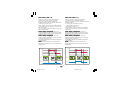
1
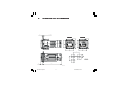
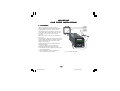
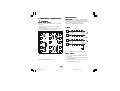
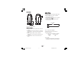
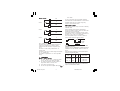
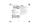
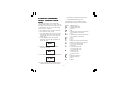
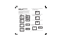
1601E
1603E
4 digit single display temperature controller
Dual 3 digit display temperature controller
U USER'S MANUAL
Issue date
November 2003
1601-03-A-CX.pmd
0037-75420
1
02/12/2003, 15.59
A. 2
1601-03-A-CX.pmd
2
02/12/2003, 15.59
INDEX
A . ORDER TABLE ...................................... A . 1
A. OUTLINE AND CUT OUT
DIMENSIONS ......................................... A . 5
1 . M O U N T I N G ................................................ 1
2 . ELECTRICAL CONNECTIONS ................. 2
3 . GENERAL OPERATION ........................... 6
4 . C O N F I G U R A T I O N ..................................... 6
4.1 Pushbutton function .............................. 6
4.2 Possible protection of the parameters ... 6
4.3 Access to the configuration
procedure .............................................. 7
4.4 Configuration parameters ...................... 7
5 . OPERATOR MODE ................................ 1 4
5.1 Preliminary comments .......................... 14
5.2 Indicators ............................................. 15
5.3 Function of the pushbuttons ................ 15
5.4 Manual reset of the alarm ................... 16
5.5 SMART algorithm ................................ 16
5.6 Inhibition of the out signal ................... 16
5.7 Direct modification of the set point ..... 17
5.8 Displaying the set point set
(model LDE) .......................................... 17
5.9 Lamp test ............................................ 17
5.10 Operative parameters .......................... 18
5.11 SP/SP2 Selection ............................... 20
5.12 Timer mode description ....................... 20
5.13 Soft Start Function .............................. 24
6 . ERROR MESSAGES .............................. 2 4
6.1 Measurement anomaly signal ............. 24
6.2 Error messages .................................... 25
6.3 List of possible errors .......................... 25
7 . TECHNICAL CHARACTERISTICS ....... 2 6
7.1 Technical specifications ...................... 26
7.2 Inputs ................................................... 26
7.3 Control actions .................................... 27
7.4 Outs ..................................................... 28
7.5 CPI - Configuration Port Interface ....... 28
8 . MAINTENANCE ....................................... 2 8
B . DEFAULT PARAMETERS .................... B . 1
A. 3
1601-03-A-CX.pmd
3
02/12/2003, 15.59
Model identification
Model
1601E
1603E
4 digit single display
Dual 3 digit display
Code
Output 1 - Heat or Cool
1
Relay, 3 Amps at 250 Vac (Resistive)
6
SSR Drive, 14 Vdc at 20 mA
Code
Output 2 - Alarm
0
None
1
Relay, 1 Amp at 250 Vac (Resistive load)
Code
0
Add to complete model number
1
Out 3 relay
2
Logic input
Code
3
5
Instrument
Power
100 - 240 Vac
24 Vac/dc
Code
1601E
1
1601-03-A-CX.pmd
1
0
3
4
0
Add to complete model number
0
Typical Model Number
02/12/2003, 15.59
A.
OUTLINE AND CUT OUT DIMENSIONS
1,5
15 max
1601E
62,8
==
48
= =
62,8
==
48
= =
1603E
48
==
48
==
60
45 0
==
+0,6
75
10
+0,6
45 0
==
105
A. 5
1601-03-A-CX.pmd
5
02/12/2003, 15.59
CUT OUT
A. 6
1601-03-A-CX.pmd
6
02/12/2003, 15.59
IMPORTANT
SAVE THESE INSTRUCTIONS
1. MOUNTING
screws
bracket
gasket
panel
Select a mounting location where there is
minimum vibration and the ambient temperature
ranges between 0 and 50°C (32 and 122°F).
The instrument can be mounted on a panel up to
15 mm thick with a square cutout of 45 x 45 mm.
For outline and cutout dimensions refer to
page A.4.
The surface texture of the panel must be better
than 6.3 µm.
The instrument is fitted with a rubber panel gasket.
To assure IP65 and NEMA 4 protection, insert the
panel gasket between the instrument and the
panel as shown in Fig. 1.
While holding the instrument against the panel
proceed as follows:
1) insert the gasket in the instrument case;
2) insert the instrument in the panel cutout;
3) pushing the instrument against the panel, insert
the mounting bracket;
4) with a screwdriver, turn the screws with a
torque between 0.3 and 0.4 Nm.
GB
1601-03-1-CX.pmd
1
Fig. 1
PANEL MOUTING
1
13/01/2004, 10.42
2 . ELECTRICAL CONNECTIONS
MEASURING INPUTS
SAFETY NOTE
NOTE: Any external components (like
zener barriers etc.) connected between sensor and
input terminals may cause errors in measurement
due to excessive and/or not balanced line
resistance or possible leakage currents.
WARNING
Electric shock Hazard
Disconnect all power before installing or servicing
controller.
Failure to do so could result in personal injury or
property damage.
Connections are to be made with the instrument
housing installed in its proper location.
TC INPUT
+ 10
_ 9
Shield
+ 10
_ 9
Shield
+
Fig. 3
SAFETY NOTES
NOTES:
1) Do not run input wires together with power
line cables.
2) For TC wiring use proper compensating cable
preferably shielded.
3) When a shielded cable is used, it should be
connected at one point only.
Fig. 2 REAR TERMINAL BLOCK
GB
1601-03-1-CX.pmd
THERMOCOUPLE CONNECTION
2
2
13/01/2004, 10.42
RTD INPUT
RTD
8
9
LOGIC INPUT
SAFETY NOTE:
1) Do not run logic input wiring together with
power cables.
2) Use an external dry contact capable of
switching 8 mA, 8 V DC.
3) The instrument needs 300 ms to recognize a
contact status variation.
4) The logic input is NOT isolated by the
measuring input
RTD
10
8
9
Log. input 2
10
11
12
Fig. 4 RTD CONNECTION
SAFETY NOTES
NOTES:
1) Do not run input wires together with power line
cables.
2) Pay attention to the line resistance; a resistance
higher than 20 Ω/wire may cause measurement
errors.
3) When shielded cable is used, it should be
grounded at one side only to avoid ground loop
currents.
4) The impedence of the 3 wires must be the
same.
Fig. 5 - LOGIC INPUT WIRING
The logic input can be programmed as:
A) Set point selector
A.1) In this case it will operate as follows:
logic input
operat. set point
open
SP
close
SP2
B) Start timer
In this case it will operate as described at
paragraph 5.10 (Timer modes description).
GB
1601-03-1-CX.pmd
3
3
13/01/2004, 10.42
RELAY OUTS
OUT 1
3
2
1
OUT 2
6
7
OUT 3
15
14
line cables.
5) OUT 3 and logic input are mutually exclusive.
NC
The follow these recommendations to avoid serious
problems which may occur when using relay
output to drive inductive loads.
C
NO
INDUCTIVE LOADS
High voltage transients may occur when switching
inductive loads.
These transients may introduce disturbances
through the internal contacts which can affect the
performance of the instrument.
The internal protection (varistors) assures correct
protection up to 0.5 A of inductive component but
the OUT 1 NC contact is not protected.
The same problem may occur when a switch is
used in series with the internal contacts.
C
NO
C
C
NO
Fig. 5 RELAY OUTS
The OUT 1 NO contact, the OUT 2 and OUT 3
contacts are protected by varistors against
inductive load with inductive component up to
0.5 A.
The OUT 1 contact rating is 3A/250V AC on
resistive load.
The OUT 2 and OUT 3 contact rating are 2A/250V
AC on resistive load.
The number of operations is 1 x 10⁵ at specified
rating.
1601-03-1-CX.pmd
4
POWER
LINE
LOAD
Fig. 6 EXTERNAL SWITCH IN SERIES WITH THE
INTERNAL CONTACT
In these cases an additional RC network should be
installed across the external contact as shown in
Fig. 6
The value of the capacitor (C) and resistor (R) are
shown in the following table.
R
(W)
P.
(W)
OPERATING
VOLTAGE
<40 mA 0.047 100
0.1
22
<150 mA
0.33 47
<0.5 A
1/2
2
2
260 V AC
260 V AC
260 V AC
LOAD
(mA)
WARNING
Electric shock Hazard
1) To avoid electric shock, connect the power
line at the end of the wiring procedure.
2) For power connections use No 16 AWG or
larger wires rated for at least 75°C.
3) Use copper conductors only.
4) Do not run input wires together with power
GB
R
C
(mF)
In every case the cable connected to the relay
outs must be routed as far away as possible from
input or communication cables.
4
13/01/2004, 10.42
VOLTAGE OUTS FOR SSR DRIVE
WARNING
SAFETY NOTE
NOTE: This out is NOT isolated.
A double or reinforced Isolation between instrument
output and power supply must be assured by the
external solid state relay.
Electric shock Hazard
1) Before connecting the instrument to the supply,
make sure that the line voltage corresponds to
that indicated on the rating plate.
2) To avoid electric shock, connect the power line at
the end of the wiring procedure.
3) For supply connections use No 16 AWG or larger
wires rated for at least 75°C.
4) Use copper conductors only.
5) Do not run input wires together with power line
cables.
6) For 24 V AC/DC the polarity does not matter.
7) The power supply input has NO fuse protection.
Please, provide a T type 1A, 250 V fuse externally.
8) The safety regulations for equipment
permanently connected to the mains require
that there is a switch or circuit breaker in the
building electrical system and that this:
- is near the device and can easily be reached by
the operator;
- is marked as the device ON/OFF .
POWER LINE WIRING
NOTE
NOTE: A single switch or circuit-breaker can drive
more than one instrument.
2
OUT 1
+
+
_
_
1
SOLID STATE
RELAY
Fig. 7
SSR DRIVE OUT WIRING
It is a time proportioning out.
0: Vout < 0.5 V DC.
Logic level 0
Logic level 1
1: Maximum current = 20 mA.
- 14 V + 20 % @ 20 mA
- 24 V + 20 % @ 1 mA.
Power Line
100 V to 240 V AC (50/60Hz)
or 24 V AC/DC
R (S,T)
N
4
N
R (S,T)
5
Fig. 8 POWER LINE WIRING
GB
1601-03-1-CX.pmd
5
5
13/01/2004, 10.42
3 . GENERAL OPERATION
4 . CONFIGURATION
There are two setup modes for these models:
- Configuration mode
- Operator mode
In general, the configuration mode is the initial
setup of the controller when first installed. Input
type and alarm setup are examples of
Configuration Mode settings. The Operator mode
includes settings that might be adjusted
frequently with daily control operations such as
setpoints, and PID parameters.
4 . 1 PUSHBUTTON FUNCTION
FUNC
This saves the new value of the
selected parameter and goes to the
next parameter (increasing order).
SMT
This scrolls back the parameters
without saving the new value.
This increases the value of the
selected parameter.
This decreases the value of the
selected parameter.
4.2 POSSIBLE PROTECTION OF THE
PARAMETERS
Access to the configuration, and the display and
modification of the operative parameters, can be
protected by a secret code. The code is entered in
configuration, by means of parameters P11 and
P14.
P11 = 0 All the operator parameters can be
displayed and modified. Access to the
configuration is free.
P11 = 1 and P14 = On All the operator parameters
can be displayed but not modified, apart from SP
(Set Point), SP2 and T. Access to the
configuration is only possible by entering code 408
when requested.
P11 = 1 and P14 = OFF No operator parameter
can be displayed and modified, apart from SP, SP2
and T. Access to the configuration is only possible
by entering code 408 when requested.
P11 = 2/499 In this case the value programmed in
P11 represents a numerical key which can be
used to protect access to the configuration and,
in operator mode, the modification of the
parameters (SP can always be modified).
To set P11 see section 4.4.
GB
1601-03-1-CX.pmd
6
6
13/01/2004, 10.42
If the modification of the parameters has been
enabled, the passage in configuration is free.
If not it will be allowed by entering, when
requested, the numerical value programmed in
P11, or code 408.
P11 = 500/999 As for the previous point, with the
difference that AL (alarm threshold) can be
modified as well as SP, SP2 and T.
code and the numerical value alternatively.
To alter the value set press
or
and confirm
with FUNC.
The parameter for loading the default parameters
is shown in section B at the end of the manual.
4.4 CONFIGURATION PARAMETERS
P1 - Type of input and standard range
In the two previous cases, with P14 = On the
parameters set as not modifiable can however be
displayed. With P14 = OFF they are not.
Type of input
0 TC type L
1 TC type J
4.3 ACCESS TO THE CONFIGURATION
PROCEDURE
To access the configuration, press SMT and
FUNC simultaneously (press first SMT and
immediately afterwards FUNC) keeping both the
pushbuttons pressed for three seconds.
In the model 1603E the lower display will show
Cnf
Cnf, the upper OFF
OFF. In model 1601E OFF and
CnF will appear alternatively.
Press
or
within 10 seconds to set ON
ON, then
confirm with FUNC.
If the device is in the protected condition (see
previous section), the lower display (1603E)
shows Cnf, the upper a dashed line (instead of
OFF
OFF). In model 1601E the two wordings appear
alternately.
By means or enter the value entered in P11, or
value 408. Press FUNC to confirm.
The instrument is now in configuration mode, and
the display shows Cnf steadily for both models.
Via FUNC we advance to the first parameters.
2
3
4
5
6
8
9
10
11
12
13
In configuration, the lower display shows the
code of the parameter (P1-P21), the upper the
numerical value or the selection code. In the
model 1601E, the display shows the parameter
GB
1601-03-1-CX.pmd
7
Range
0 / +900 °C
0 / +999 °C
(1603E)
0 / +1000 °C
(1601E)
TC type K
0 / +999 °C
(1603E)
0 / +1370
(1601E)
TC type N
0 / +999 °C
(1603E)
0 / +1400 °C
(1601E)
RTD type Pt 100 -199 / +800 °C
(1603E)
-200 / +800 °C
(1601E)
RTD type Pt 100 -19.9 / +99.9 °C (1603E)
-199.9 / +400.0 °C (1601E)
TC type T
0 / +400 °C
TC type L
0 / 999 °F
(1603E)
0 / 1652 °F
(1601E)
TC type J
0 / 999 °F
(1603E)
0 / 1832 °F
(1601E)
TC type K
0 / 999 °F
(1603E)
0 / 2498 °F
(1601E)
TC type N
0 / 999 °F
(1603E)
0 / 2552 °F
(1601E)
RTD type Pt 100 -199 / 999 °F
(1603E)
-328 / 1472 °F
(1601E)
TC type T
0 / 752 °F
NOTE: On the instrument front panel two leds
indicate the setting of the temperature in °C or °F,
depending on the configuration.
7
13/01/2004, 10.42
P5 = Function of Out 2
0 = Not used or used as event (P22 = 3, 4, 6, 7)
1 = Alarm 1 output - Process alarm
2 = Alarm 1 output - Band alarm
3 = Alarm 1 output - Deviation alarm
4 = Alarm 1 output - Instrument failure alarm
5 = Cooling out
P2 = Initial range value
Initial range value for input from thermocouple/
Resistance Temperature Detector.
NOTES
NOTES:
1) When P2 has been modified, the rL parameter
will be aligned to it and rH parameter will be
forced to P3 value is rH < rL
rL.
2) When P2 has been modified, if the alarms are
programmed as process alarms (P5=1 and/or
P22=1) and the alarm thresholds are out of
range, AL.1 and/or AL. 2 will be aligned to P2.
P3 = Full range value
Full range value for input from thermocouple/
Resistance Temperature Detector.
NOTES
NOTES: The minimum input span (P3 - P2) is
300°C or 600°F for TC input and 100°C or 200°F
for RTD input.
On every parameter change P1, P2 is forced to
the minimum value, P3 to the maximum value.
If the value of P2 and/or P3 is modified the
parameter rL is automatically aligned to the new
value (of P2 and/or P3).
If P5 = 1, parameter rL is checked and
automatically aligned if it is out of range.
P4 = Out 1 action
This parameter is not modifiable when P5 = 5
r E U = reverse action (Heating)
d i r = direct action (Cooling)
Reverse
Direct
Input
P6 = Configuration Out 2
P6 is skipped when P5 = 0.
If P5 = 1, 3 or 4;
H . A . = High alarm with automatic reset
L . A . = Low alarm with automatic reset
H . L . = High alarm with manual reset
L . L . = Low alarm with manual reset
When P5 = 4, the "high" or "low" selection has no
effect.
Input
t
Out
t
Out
t
t
GB
1601-03-1-CX.pmd
NOTES:
1) Setting P5 = 1, 2, 3:
- if parameter OLH is less than 0, it is set to
100;
- if parameter IP is less than 0, it is set to 30;
- if parameters AL1 is out of range, it will be
aligned to the lowest value.
2) Setting P5 = 0 or 4:
- if parameter OLH is less than 0, it is set to
100;
- if parameter IP is less than 0, it is set to 30;
3) Setting P5 = 5:
- parameter P4 automatically assumes the value
rEU
“rEU
rEU”;
- if parameter P16 is out of range, it will be
aligned to the lowest value;
- if parameter Pb is not 0 and is lower than 1.5,
it is set to 1.5.
4) Setting P5 different 0:
- if P22 parameter is equal to 3, 4, 6 or 7 it will
be forced to 0.
8
8
13/01/2004, 10.42
If P5 = 2:
H . A . = out of band with automatic reset
L.A. = in band with automatic reset
H.L. = out of band with manual reset
L.L. = in band with manual reset
When P5 = 5 this parameter selects the cooling
medium.
AIr = air
OIL = oil
H2O = water
NOTE
NOTE: Modifying parameter P6 automatically
updates the values of the cooling cycle time
and the cooling gain.
P6
Air
OIL
H2O
C2
10 (s)
4 (s)
2 (s)
Readout
P9
P 1 0 = Threshold of the “Soft Start”
function
The “Soft start” function limits the maximum out
power (see OLH operator parameter) for a
programmable time (see tOL operator parameter)
at the instrument start up when the measured
value is lower then the programmed threshold.
P10 is the threshold value, in engineering units.
L = InF
If tO
tOL
InF, P10 value is not considered.
P7 = Alarm action
Only available when P5 is different from 0 or 5.
rEU = reverse (relay de-energized in alarm
condition)
dir = direct (relay energized in alarm condition)
P8 = Alarm inhibit
Only available when P5 is 1, 2 or 3.
O F F = inhibit disabled
O N = inhibit enabled
Every time parameter P1 is changed it is forced to
the minimum value.
P 1 1 = Safety lock
0 = device unlocked. All the parameters can be
modified
1 = device locked. None of the parameters can be
modified except the SP
SP, sp2 and t .
2 to 499 = SP
SP, sp2 and t can be always
modified.
Select the secret code (to be remembered) and
during the “operative mode” and scrolling the
“software key” parameter, the display will show
one of the following figures:
NOTE
NOTE: The alarm inhibit function disables the
alarm indication at instrument start up and after a
set point modification until the process variable
reaches the alarm threshold.
P9 = OFFSET applied to the measured
value
This OFFSET is applied along the whole span.
When P1= 5
P9 is programmable from -19.9
to 19.9°C.
When P1 ≠ 5
P9 is programmable from -199
to 199°C or °F.
1601-03-1-CX.pmd
9
Adjusted
curve
Input
RC
1
0.8
0.4
GB
Real curve
A)
OFF
nnn
The device is “Unlocked”
and all parameters can be
modified.
9
13/01/2004, 10.42
To make the device
“Locked” enter a number
different from the “secret
code”.
B)
O N The key is enabled: no
can be modified
nnn parameter
apart from SP
SP, sp2 and t .
To “Unlock” the device,
insert the “secret code”.
500 to 999: Selecting a secret code between
these two numbers, everything will occur as
explained above except that when the device is
“Locked” the parameters that can be modified are
the set point and the alarm threshold and the time.
NOTE: The instrument shows on the display the
value 2 for any value of P11 between 2 and 999.
P 1 2 = Out maximum rate of rise
This parameter is only available if Pb is not 0.
Programmable from 1 to 25% of the out signal per
second.
InF
Over 25%/s the instrument displays “InF
InF” to
indicate the exclusion of the limitation.
P13 = Not used
P14 = Protected parameters display
This parameter is only available if P11 is not 0.
This parameter enables/disables the display of the
protected parameter during "operator mode".
O F F = the protected parameters are not displayed
O N = the protected parameters are displayed
P 1 5 - SMART function enabling/
disabling
0 = The SMART function is disabled
1 = SMART function enabling/disabling is
NOT protected by the safety code.
2 = SMART function enabling/disabling is
protected by the safety code.
P16 - Maximum value of the proportional band
automatically settable by the SMART
function
This parameter is available if P15 is not 0. It can
assume the following values:
model 1603E:
between P17 or P18 and 99.9%
model 1601E:
between P17 or P18 and 100.0%
P 1 7 - Proportional minimum band value
automatically settable by the
SMART function ( one control out
only)
This parameter is only displayed if P5 is not 5 or
P15 is not 0.
It may be programmed from 1.0% to the value of
P16.
P 1 8 - Proportional minimum band value
automatically settable by the
SMART function (two control outs,
heating/cooling)
This parameter is only present if P5 is 5 and P15 is
not 0.
This parameter may be programmed from 1.5% to
the value of P16.
G B 10
1601-03-1-CX.pmd
10
13/01/2004, 10.42
P 1 9 = Automatic calculation of "relative
cooling gain"
This parameter is only present if P5 is 5 and P15
is not 0.
O F F = the SMART function does NOT calculates
the "relative cooling gain".
ON = the SMART function calculates the "relative
cooling gain".
P20 = Minimum integral time value calculated
by the SMART function
This parameter is only present if P15 is not 0.
It can assume the following values:
model 1603E: between 0.1 (1 tenth of a second)
and 2.0 (2 minutes)
model 1601E: between 00.01 (1 second) and
2.00 (2 minutes).
P 2 1 = Extension of the anti-reset-wind
up
Span: from -30 to +30 % of the proportional band.
NOTE
NOTE: a positive value increases the high limit of
the anti-reset-wind up (over set point) while a
negative value decreases the low limit of the antireset-wind up (under set point).
The advanced configuration procedure is
CnF
completed and the instrument shows "CnF
CnF" on the
display.
To quit the configuration, press SMT and FUNC
simultaneously (press first SMT and immediately
afterwards FUNC) keeping both the pushbuttons
pressed for three seconds.
P22 - Option selection (out 3 or digital
input)
0 = output not used
1 = Alarm 2 output - Process alarm
2 = Alarm 2 output - Band alarm
3 = Alarm 2 output - Deviation alarm
4 = Digital input used for SP/SP2 selection.
5 = Timer mode 1 (see below)
6 = Timer mode 2 (see below)
7 = Timer mode 3 (see below)
8 = Timer mode 4 (see below)
9 = Timer mode 5 (see below)
10 = Timer mode 6 (see below)
11 = Timer mode 7 (see below)
Note:
1) Select P22 value in accordance with the
installed hardware.
2) Setting P22 equal to 1, 2 or 3, if AL2
parameter is out of range, it will be aligned to
its low limit.
3) Setting P22 equal to 4, 5 or 8, if sp2
parameter is out of range, it will be aligned to
rl value.
4) Setting P22 equal to 6 or 7,P5 parameter will
be forced to 0 and if sp2 parameter is out of
range, it will be aligned to rl value.
5) Setting P22 equal to 9 or 10,P5 parameter will
be forced to 0.
6) When P22 parameter pass from a value equal
or greater than 9 to e value lower than 9, at
the next start up the controll output will be
forced to "enabled".
Timer functions
Notes about all timer modes:
1) At power off the time value and status will be reset.
t) can always be modified
2) The time parameter (t
but the new value become operative at the next
start time only.
G B 11
1601-03-1-CX.pmd
11
13/01/2004, 10.42
Timer mode 1 [P22 = 5]
If the logic input remains in open condition for
more than a programmed time the instrument goes
automatically at a stand by temperature (SP2).
The time count is reset when the logic input is
closed.
For other details see paragraph "5.7 Timer
modes description".
Timer mode 2 [P22 = 6]
When the contact is closed, the instrument
controls using SP as operative set point.
When the contact has been opened the instrument
selects SP2 as operative set point and starts the
time count down.
Note that the guarantee soak function can be
applied to this timer mode (see P28 parameter)
When the time count is equal to 0 the instrument
comes back to the SP set point and the output 2
will be energized.
The Out 2 reset will be made when the logic input
will be closed again.
For other details see paragraph "5.7 Timer
modes description".
Timer mode 3 [P22 = 7]
When the contact is closed, the instrument
controls using SP as operative set point.
When the contact has been opened the instrument
operate as follows:
- it selects SP2 as operative set point
- it starts the time count down
- it energizes the Output 2
Note that the guarantee soak function can be
applied to this timer mode (see P28 parameter)
When the time count is equal to 0 the instrument
comes back to the SP set point and the output 2
will be reset.
For other details see paragraph "5.7 Timer
modes description".
Timer mode 4 [P22 = 8]
The instrument operates using SP set point and
the timer is normally reset.
When the instrument detects the transfer from
contact open to close it selects SP2 as operative
set point and starts the time count down.
Note that the guarantee soak function can be
applied to this timer mode (see P28 parameter)
When the time count is equal to 0 the instrument
comes back to the SP set point.
For other details see paragraph "5.7 Timer
modes description".
Timer mode 5 [P22 = 9]
The instrument start in "Power OFF" mode and it
remains in "Power OFF" mode until the contact is
closed.
When the contact has been opened the instrument
starts the control using SP set point and starts the
time count down.
Notes:
1) The guarantee soak function can be applied to
this timer mode (see P28 parameter)
2) The transfer from "Power OFF" mode to
AUTOMATIC mode starts the "Soft start" and the
"alarm masking" functions (if programmed).
When the time count is equal to 0 the instrument
comes back to the "Power OFF" mode and the
output 2 will be energized.
G B 12
1601-03-1-CX.pmd
12
13/01/2004, 10.42
The Out 2 reset will be made when the logic input
will be closed.
For other details see paragraph "5.7 Timer
modes description".
Timer mode 6 [P22 = 10]
The instrument starts in "Power OFF" mode and it
remains in "Power OFF" mode until the contact is
closed.
When the contact has been opened the instrument
operate as follows:
- it starts the control using SP set point.
- it starts the time count down
- it energizes the Output 2
Notes:
1) The guarantee soak function can be applied to
this timer mode (see P28 parameter)
2) The transfer from "Power OFF" mode to
AUTOMATIC mode starts the "Soft start" and the
"alarm masking" functions (if programmed).
When the time count is equal to 0 the instrument
comes back to the "Power OFF" mode and the
output 2 will be reset.
For other details see paragraph "5.7 Timer
modes description".
Timer mode 7 [P22 = 11]
The instrument starts in "Power OFF" mode and it
remains in "Power OFF" mode until a transfer from
open to close of the logic input is detected.
When the instrument detects the transfer from
contact open to close it starts the control using
SP set point and starts the time count down.
Notes:
1) The guarantee soak function can be applied to
this timer mode (see P28 parameter)
2) The transfer from "Power OFF" mode to
AUTOMATIC mode starts the "Soft start" and the
"alarm masking" functions (if programmed).
When the time count is equal to 0 the instrument
comes back to the "Power OFF" mode .
For other details see paragraph "5.7 Timer
modes description".
P23 = Alarm 2 configuration
P23 is skipped when P22 is equal to 0
If P22 = 1 or 3
H . A . = High alarm with automatic reset
L . A . = Low alarm with automatic reset
H . L . = High alarm with manual reset
L . L . = Low alarm with manual reset
If P22 = 2:
H . A . = out of band with automatic reset
L . A . = in band with automatic reset
H . L . = out of band with manual reset
L . L . = in band with manual reset
P24 = Alarm 2 action
P24 is available when P22 is 1, 2 or 3.
r E U = reverse (relay de-energized in alarm
condition)
d i r = direct (relay energized in alarm condition)
P25 = Stand-by of the alarm 2
P25 is available when P5 is 1, 2 or 3.
OFF
= stand-by disabled
ON
= stand-by enabled
G B 13
1601-03-1-CX.pmd
13
13/01/2004, 10.42
NOTE
NOTE: The alarm stand-by function disables the
alarm indication at instrument start up and after a
set point modification until the process variable
reaches the alarm threshold.
5 . OPERATOR MODE
P26 = treshould of the guarantee soak
function
P26 is available when P22 is greater than 2.
This function stop automatically the time count
down when the measured value is out of the band
defined by the set point plus and minus P26 value.
- When P1 = 5 : P26 is programmable from 0.1 to
50.0 eng. units.
- When P1 ≠ 5 : P26 is programmable from 1 to
500 eng. units.
Above max value the display shows “OFF” and this
finction is disabled.
5 . 1 PRELIMINARY COMMENTS
It is assumed, at this point, that the instrument has
been correctly configured as indicated in
Section 4.
The configuration procedure is completed and the
CnF
instrument shows "CnF
CnF" on the display.
To quit the configuration, press SMT and FUNC
simultaneously (press first SMT and immediately
afterwards FUNC) keeping both the pushbuttons
pressed for three seconds.
The display and modification of the operator
parameters can be protected by a secret code.
For more information see section 4.2.
- Model 1603E displays the value measured on
the upper display: the lower display is normally
used to display the operating set point (below
this condition is defined as “Normal display”).
- Model 1601E displays the value measured
(below this condition is defined as “Normal
display”) or, alternatively, the operating set point
(in this case the SP led lights up).
To change from the display of the set point to
that of the value measured, or vice versa, press
pushbutton
.
All the parameters can be displayed sequentially by
pressing the FUNC pushbutton.
- Model 1603E displays the abbreviated name of
the parameter selected on the lower display, on
the upper display the value set.
- Model 1601E displays alternatively the name of
the parameter and its value: during the
modification it displays only the value.
To modify the setting of a parameter proceed as
follows:
1) By means of the FUNC pushbutton select the
parameter to be modified.
2) Using the
and
keys set the value
required.
G B 14
1601-03-1-CX.pmd
14
13/01/2004, 10.43
3) Press the FUNC pushbutton to save the new
value and go to the next parameter.
4) Press SMT to return to the previous parameter
without saving.
NOTES
NOTES:
1) If, during parameter modification, no
pushbutton is pressed for more than 10
seconds, the instrument automatically reverts
to the “normal display mode” and the new
setting of the last parameter will be lost.
2) In the “normal display”, on pressing pushbutton
or
and keeping it pressed for more than
two seconds, one can directly access the set
point value, which can be modified by pressing
or
again (see section 5.7).
3) The instrument does not display all the possible
parameters, but only those which are in
agreement with:
a) The instrument configuration (see section 4).
b) The setting of parameter P14 (see section
4).
c) The setting of the proportional band (see
section 5.5).
5 . 2 INDICATORS
SMT Flashes when the first part of the SMART
algorithm is active.
Lit when the second part of the SMART
algorithm is active.
OUT1 Lit up when out 1 is ON.
OUT2 A) When used as event or cooling output it
lit up when out 2 is ON.
B) When used as alarm indication:
B.1) Lit if only Alarm1 is in alarm
condition.
B.2) Flashing at slow rate (0.5 Hz) if only
Alarm 2 is in alarm condition.
B.3) Flashing at fast rate ( 2 Hz) if both
alarms are in alarm condition.
Lit up if the temperature is displayed in °C.
Lit up if the temperature is displayed in °F.
(1601E only) Lit when the display shows the
operative set point.
In addition
addition:
a)
The decimal point on the right hand of the
LSD of the upper display, for 1603E, or of
the display, for 1601E, flashes when the
instrument is working with SP2.
b)
The decimal point on the left hand of the
LSD of the lower display, for 1603E, or of
the display, for 1601E, flashes when the
display shows the time count down.
°C
°F
SP
5 . 3 FUNCTION OF THE PUSHBUTTONS
FUNC
Saves the new value of the selected
parameter and goes to the next
parameter (increasing order).
SMT
Enables or disables the SMART
function and scrolls back all the
parameters without saving them.
Increases the value of the selected
parameter or (1601E only) displays the
set point value or the measured value.
Decreases the value of the selected
parameter.
+ FUNC Enables/disables the "LAMP TEST".
NOTE
NOTE: The operator parameters must be modified
within 10 seconds. If, during operator parameter
modification, no pushbutton is pressed during this
time, the instrument automatically reverts to the
“normal display mode”. Saving only the parameter
modifications which were followed by pressing the
FUNC pushbutton.
G B 15
1601-03-1-CX.pmd
15
13/01/2004, 10.43
5 . 4 MANUAL RESET OF THE ALARM
If the alarm has been configured as a latched
alarm, the alarm status persists even after the
alarm condition disappears.
To reset the alarm, press the FUNC pushbutton to
n.rS
select the parameter “n.rS
n.rS” (the display will show
n.rS
OFF
“n.rS
n.rS” and “OFF
OFF”. Use the
and
pushbuttons
ON
to select “ON
ON” and press the FUNC pushbutton.
The alarm reset action will only be successful if the
alarm condition has disappeared.
3) The limits of the proportional band settable by
the SMART function are programmed by
parameters P16, P17 and P18 .
4) The lower limit of the integral time settable by
the SMART function is programmed by
parameter P20 .
5) When ON/OFF control is programmed (Pb=0),
the SMART function is disabled.
6) SMART enabling/disabling can be protected by
the safety lock (see parameter P15).
5 . 5 SMART ALGORITHM
This function gives best process control.
To enable the SMART function, press the SMT
pushbutton for more than 1.5 s, when the
instrument is in normal display mode. The SMT
LED will be lit continuously or flash according to
the algorithm automatically selected.
When the SMART function is enabled, the
PB
traditional control parameters (PB
PB,, TI
TI,, TD and
rC
rC) can be displayed but not modified.
When the traditional control (PID) is desired, press
the SMT pushbutton again (for more than 1.5 s) to
turn the "SMART" OFF. The instrument maintains
the actual control parameters setting and allows
parameter modification.
5 . 6 INHIBITION OF THE OUT SIGNAL
This feature manually turn OFF the control output.
To turn the out signal OFF, press the
pushbutton first and then press the FUNC
pushbutton.
Keeping them both pressed for more than 3
seconds.
OFF
The instrument will display “OFF
OFF” instead of
indicating the set point; the out signal will switch
OFF and the instrument will work as a simple
indicator.
When the control outs are disabled, the alarms are
also disabled and forced to the no-alarm condition.
The modification of the control parameters is still
enabled.
To return to normal control, press the pushbutton
first and then press the FUNC pushbutton.
Keeping them both pressed for more than
3 seconds, the instrument returns to normal display
mode.
NOTES :
1) If the out is turned OFF when the SMART
function is performing the first part of the SMT
algorithm (LED SMT flashing), the SMART
function will be aborted and when the
instrument comes back to the normal control,
the SMART function will be disabled.
NOTES
NOTES:
1) During operation of the SMART function, the
relative cooling gain (if controlled by SMART) is
limited within the following ranges:
Cooling medium
Span
Air
0.85 to 1.00
OIL
0.80 to 0.90
H2O
0.30 to 0.60
2) The SMART function uses a derivative time equal
to 1/4 of the integral time.
G B 16
1601-03-1-CX.pmd
16
13/01/2004, 10.43
If the out is turned OFF when the SMART
function was performing the second part of the
SMT algorithm (LED SMT lit), the SMART
function will be stopped and, when the
instrument comes back to the normal control,
the smart function will also be activated.
2) If the instrument is turned OFF with the out
power off function enabled, at the next start up
this function will automatically be enabled
again.
5 . 7 DIRECT MODIFICATION OF
THE SET POINT
The set point value can be modified without using
the FUNC pushbutton.
When direct access to set point modification is
required, proceed as follows:
1) Press pushbutton or for more than
2 seconds; the set point value will be
displayed and it will start to change.
2) Using the
and
pushbuttons, set the
desired value.
3) When the desired value is reached, DO NOT
press any pushbutton, the new set point will
become operative 2 seconds after the
pushbuttons were last pressed and the
instrument will return to the “normal display”.
If during this procedure the modification is not to
be saved, press the FUNC pushbutton
immediately (within 2 seconds); the instrument
automatically returns to the normal display without
saving the new set point.
5 . 8 DISPLAYING THE SET POINT SET
(model 1601E)
To display the set point set, press the
pushbutton. The SP led lights up.
The set point value will appear on the display.
To return to the display of the value measured
press pushbutton
again.
5 . 9 LAMP TEST
To check the display efficiency, press pushbuttons
+ FUNC. The instrument will turn ON, with a
50% duty cycle, all the LEDs of the display (this
state is called LAMP TEST).
No time out is applied to the LAMP TEST.
To return to the normal display mode, press
pushbuttons
+ FUNC again.
No other keyboard functions are available during
the LAMP TEST.
G B 17
1601-03-1-CX.pmd
17
13/01/2004, 10.43
5 . 1 0 OPERATIVE
PARAMETERS
The following is a list of all the available control
parameters.
Note that some parameters may not be displayed
depending on the specific instrument
configuration.
SP2
t
To modify the setting of a parameter proceed as
follows:
1) By means of the FUNC pushbutton select the
parameter to be modified.
2) Using the
and
keys set the value
required.
3) Press the FUNC pushbutton to save the new
value and go to the next parameter.
4) Press SMT to return to the previous parameter
without saving.
nnn
NOTES
NOTES:
1) If, during parameter modification, no
pushbutton is pressed for more than 10
seconds, the instrument automatically reverts
to the “normal display mode” and the new
setting of the last parameter will be lost.
2) The instrument does not display all the possible
parameters, but only those which are in
agreement with:
a) The instrument configuration (see section 4).
b) The setting of parameter P14 (see section
4).
c) The setting of the proportional band (see
section 5.5).
AL.1
Param. Description
SP
Set point (in eng. units).
Span: from rL to rH.
n.rS
Manual reset of the alarms.
This parameter is displayed if one alarm
has been programmed with manual reset.
HS.1
Set ON and press the FUNC pusbutton
to reset the alarms.
Set point 2 (in eng. units).
This parameter is present if P22 = 1, 2, 3,
4 or 5.
Span: from rL to rH.
time of the timer function (in minutes and
seconds).
This parameter is present if P22 greater
than 4.
Span: from 10 seconds (00.1) to 90
minutes (90.0).
Software key for parameter protection.
This parameter is skipped if P11 = 0 or 1.
ON = the instrument is in LOCK
condition
OFF = the instrument is in UNLOCK
condition.
To switch from LOCK to UNLOCK, set a
value equal to the value of parameter
P11.
To switch from UNLOCK to LOCK, set a
value different from the value of parameter
P11.
Span: 2/999
Alarm 1 threshold (in eng. units).
This parameter is available only if
P5 = 1, 2 or 3.
Spans:
- From P2 to P3 for process alarm
(P5 = 1)
-
From 0 to 500 units for band alarm
(P5 = 2).
- From -199 to 500 units for deviation
alarm (P5 = 3).
Alarm 1 hysteresis (in % of P3 - P2 span).
This parameter is available only if
P5 = 1, 2 or 3.
Span: From 0.1% to 10.0% of the input
G B 18
1601-03-1-CX.pmd
18
13/01/2004, 10.43
AL.2
HS.2
Pb
-
span or 1 LSD.
Note: If the hysteresis of a band alarm is
Note
larger than the alarm band, the
instrument will use an hysteresis value
equal to the alarm band minus 1 digit.
Alarm 2 threshold (in eng. units).
This parameter is available only if
P22 = 1, 2 or 3.
Spans:
- From P2 to P3 for process alarm
(P5 = 1)
- From 0 to 500 units for band alarm
(P5 = 2).
- From -199 to 500 units for deviation
alarm (P5 = 3).
Alarm 1 hysteresis (in % of P3 - P2 span).
This parameter is available only if
P22 = 1, 2 or 3.
Span: From 0.1% to 10.0% of the input
span or 1 LSD.
Note
Note: If the hysteresis of a band alarm is
larger than the alarm band, the
instrument will use an hysteresis value
equal to the alarm band minus 1 digit.
Proportional band (in % of P3 - P2 span).
Span:
- For one control output: from 1.0% to
99.9% (from 1.0% to 100.0% for model
1601E) of the input span (P3-P2).
For two control outputs: from 1.5% to
99.9% (from 1.5% to 100.0% for model
1601E) of the input span (P3-P2)
When the the SMART is ON (see section
5.2) the value of Pb is limited to that set
in P16-P17 (one control action) and to
that set on P16-P18 (two control actions).
When Pb parameter is set to 0, the
instrument performs an ON-OFF control;
HS
ti
td
IP
C
C2
the ti, td, IP, C, C2, rC, OLP, OLH and
tOL parameters are skipped and the
"output max. rate of rise" and SMART
functions are not available.
Hysteresis for ON/OFF control action (in
% of P3 - P2 span).
This parameter is only available when
Pb = 0.
Span: from 0.1% to 10.0% of the input
span.
Integral time. Is skipped when Pb = 0
(ON/OFF action).
Span model 1603E: from 0.1 to 20.0
mm.s (minutes and tens of seconds).
Span model 1601E: from 00.01 to
20.00 mm.ss (minutes and seconds)
Above this value the display becomes
dark and the integral action is excluded.
Derivative time. This parameter is skipped
if Pb = 0 (ON/OFF action).
Span model 1603E: from 0.00 to 9.59
mm.ss (minutes and seconds)
Span model 1601E: from 0.00 to 10.00
mm.ss (minutes and seconds).
If 0 is set, the derivative action is
excluded.
Integral pre-load. This parameter is only
available when Pb is not 0.
Span:
- from 0 to 100% for one control output
- from -100 to 100% for two control
outputs.
Out 1 cycle time (in seconds).
This parameter is only available when Pb
is not 0.
Span: from 1 to 200 s.
Out 2 cycle time (in seconds).
C2 is only available if Pb is not 0 and P5
is 5.
G B 19
1601-03-1-CX.pmd
19
13/01/2004, 10.43
OLP
rL
rH
OLH
-
tOL
Span: from 1 to 200 s.
Relative Cooling gain.
This is skipped if Pb = 0 (ON/OFF action)
or P5 is not 5.
Span: from 0.20 to 1.00
Dead band/Overlap between H/C outs (in %
of the proportional band).
“OLP” is skipped if Pb = 0 (ON/OFF
action) or P5 is not 5.
A negative value shows a dead band
while a positive value shows an overlap.
Span: from -20 to 50%.
Set point low limit (in eng. units).
Span: from min. range value (P2) to rH.
Note
Note: when rL value has been chenged,
if the SP and SP2 value are lower than
the new rL value, thay will be alligned to
the new rL value.
Set point high limit (in eng. units).
Range:from rL to full scale value (P3).
Note
Note: when rH value has been chenged,
if the SP and SP2 value are higher than
the new rH value, thay will be alligned to
the new rH value.
Out maximum limit (in % of the out).
Span:
From 0 to 100 when the instrument is
configured with one control out.
- From -100 to 100 when the instrument
is configured for two control outs.
Duration of the out power limiter (in
minutes).
Available only if Pb is not 0.
Span: from 1 to 540 min. Above this limit,
Inf
the display shows "Inf
Inf" and the
limitation is always entered.
Note
Note: Parameter tOL can be modified
but the new value will only become
operative at the next instrument start up
unless the new value is Inf
Inf.
G B 20
1601-03-1-CX.pmd
20
5.11 SP/SP2 SELECTION
When P22= 0 the set point 2 is not available.
When P22 = 1, it is possible to select the operating
set point (SP or SP2) by the logic input only (terminals
11 and 12).
When P22 > 1 the set point selection is managed
by timer function and no manual selection is
available
5.12 Timer modes description
Timer mode 1 [P22 = 5]
If the logic input remains in open condition for more
than a programmed time the instrument goes
automatically to a stand by temperature (SP2).
The time count is reset when the logic input is
closed.
1603E display management
management: the upper
display shows the measured value while the lower
display shows the operative set point.
1601E display management
management: the display
shows the measured value.
Pushing
pushbutton it is possible to display the
operative set point.
SP
Programmed
time
rC
SP2
Time
Logic input
Closed
Open
Open
13/01/2004, 10.43
Closed
Timer mode 2 [P22 = 6]
When the contact is closed, the instrument
controls using SP as operative set point.
When the contact has been opened, the
instrument selects SP2 as operative set point and
starts the time count down.
When the time count is equal to 0 the instrument
comes back to the SP set point and the output 2
will be energized.
The Out 2 reset will be made when the logic input
will be closed again.
1603E display management
management: when the
instrument starts the time count down, the upper
display shows the measured value while the lower
display shows time count down.
1601E display management
management: when the
instrument starts the time count down, the display
shows the time count down.
Pushing
pushbutton it is possible to display the
measured value.
NOTE
NOTE: for both instruments, when the time is
finished the instrument comes back to the normal
display mode.
Timer mode 3 [P22 = 7]
When the contact is closed, the instrument
controls using SP as operative set point.
When the contact has been opened the instrument
operates as follows:
- it selects SP2 as operative set point
- it starts the time count down
- it energizes the Output 2
When the time count is equal to 0 the instrument
comes back to the SP set point and the output 2
will be reset.
1603E display management
management: when the
instrument starts the time count down, the upper
display shows the measured value while the lower
display shows time count down.
1601E display management
management: when the
instrument starts the time count down, the display
shows the time count down.
Pushing
pushbutton it is possible to display the
measured value.
NOTE
NOTE: for both instruments, when the time is
finished the instrument comes back to the normal
display mode.
SP2
SP2
Programmed
time
SP
SP
Time
Time
Stop
Run
Stop
Run
Stop
Paint
Run
Dry
Paint
Dry
Paint
Dry
Contact
Contact
Closed
Open
Closed
Closed
Open
Open
Closed
Open
Output 2
Output 2
OFF
OFF
ON
OFF
OFF
ON
G B 21
1601-03-1-CX.pmd
21
13/01/2004, 10.43
OFF
Timer mode 4 [P22= 8]
The instrument operates using SP set point and
the timer is normally reset.
When the instrument detects the transfer from
contact open to close it selects SP2 as operative
set point and starts the time count down.
When the time count is equal to 0 the instrument
comes back to the SP set point.
1603E display management
management: when the
instrument starts the time count down, the upper
display shows the measured value while the lower
display shows time count down.
1601E display management
management: when the
instrument starts the time count down, the display
shows the time count down.
Pushing
pushbutton it is possible to display the
measured value.
NOTE
NOTE: for both instruments, when the time is
finished the instrument comes back to the normal
display mode.
Timer mode 5 [P22 = 9]
The instrument start in "Power OFF" mode and it
remains in "Power OFF" mode until the contact is
closed.
When the contact has been opened the instrument
starts the control using SP set point and starts the
time count down.
When the time count is equal to 0 the instrument
comes back to the "Power OFF" mode and the
output 2 will be energized.
The Out 2 reset will be made when the logic input
will be closed.
1603E display management
management: when the
instrument starts the time count down, the upper
display shows the measured value while the lower
display shows time count down.
1601E display management
management: when the
instrument starts the time count down, the display
shows the time count down.
Pushing
pushbutton, it is possible to display the
measured value.
NOTE
NOTE: for both instruments, when the time is
finished the instrument comes back to the usual
display of the Power OFF mode.
SP2
SP
SP
Time
Logic input
Open
Closed
Open
Open
Output
Power
OFF
Output
Power
OFF
Time
Stop
Run
Stop
Run
Stop
Run
Contact
Closed
Open
Closed
Open
Output 2
G B 22
1601-03-1-CX.pmd
22
OFF
OFF
13/01/2004, 10.43
ON
OFF
Timer mode 6 [P22 = 10]
The instrument starts in "Power OFF" mode and it
remains in "Power OFF" mode until the contact is
closed.
When the contact has been opened the instrument
operates as follows:
- it starts the control using SP set point.
- it starts the time count down
- it energizes the Output 2
When the time count is equal to 0 the instrument
comes back to the "Power OFF" mode and the
output 2 will be reset.
1603E display management
management: when the
instrument starts the time count down, the upper
display shows the measured value while the lower
display shows time count down.
1601E display management
management: when the
instrument starts the time count down, the display
shows the time count down.
Pushing
pushbutton, it is possible to display the
measured value.
NOTE
NOTE: for both instruments, when the time is
finished the instrument comes back to the usual
display of the Power OFF mode.
Timer mode 7 [P22 = 11]
The instrument starts in "Power OFF" mode and it
remains in "Power OFF" mode until a transfer from
open to close of the logic input is detected.
When the instrument detects this transfer, it starts
the control using SP set point and starts the time
count down.
When the time count is equal to 0 the instrument
comes back to the "Power OFF" mode .
1603E display management
management: when the
instrument starts the time count down, the upper
display shows the measured value while the lower
display shows time count down.
1601E display management
management: when the
instrument starts the time count down, the display
shows the time count down.
Pushing
pushbutton, it is possible to display the
measured value.
NOTE
NOTE: for both instruments, when the time is
finished the instrument comes back to the usual
display of the Power OFF mode.
SP
SP
Output
Power
OFF
Output
Power
OFF
Time
Output
Power
OFF
Output
Power
OFF
Contact
Open
Closed
Open
Time
Stop
Run
Stop
Run
Stop
Run
Contact
Closed
Open
Closed
Open
Output 2
OFF
ON
OFF
G B 23
1601-03-1-CX.pmd
23
13/01/2004, 10.43
Open
5.13 “Soft Start” FUNCTION
At power up, the instrument will measure the
process variable and compare the measured value
with a programmed threshold (see P10 parameter
in chapter 4).
If the measured value is lower than the programmed value, the instrument will limit the
maximum output power (see OLH operative
parameter) for a programmed time (see tOL
operative parameter).
If tOL is equal to InF, the limiter is ever active.
6 . ERROR MESSAGES
6 . 1 MEASUREMENT ANOMALY SIGNAL
The instrument display (the upper display for model
1603E) shows the OVERRANGE and UNDERRANGE
conditions with the following indications:
Overrange
Underrange
The example shows the display of model 1603E.
Model 1601E displays 4 digits.
The sensor break can be signalled as:
- for TC/mV input
: OVERRANGE or
UNDERRANGE selected by
a solder jumper
- for RTD input
: OVERRANGE
On RTD input, a special test is provided to signal
OVERRANGE when input resistance is less than 15
ohm (Short circuit sensor detection).
NOTE
NOTE:
When:
- The instrument is set for one control out only and
an OVERRANGE is detected, the OUT 1 turns
OFF (if reverse action) or ON (if direct action).
- The instrument is set to use two control outs and
an OVERRANGE is detected, OUT 1 turns OFF
and OUT 2 turns ON.
- The instrument is set for one control out only and
an UNDERRANGE is detected, the OUT 1 turns
ON (if reverse action) or OFF (if direct action).
G B 24
1601-03-1-CX.pmd
24
13/01/2004, 10.43
- The instrument is set to use two control outs and
an UNDERRANGE is detected, OUT 1 turns ON
and OUT 2 turns OFF.
For inputs from thermocouple the underrange
indication can be selected as shown in section 7.2
of this manual.
N O T E : When an overrange or an underrange is
detected, the alarms operate as if the
instrument had detected the maximum or
the minimum measurable value
respectively.
To eliminate the out of span condition, proceed as
follows:
1) Check the input signal source and the
connecting line.
2) Make sure that the input signal is in
accordance with the instrument configuration.
Otherwise, modify the input configuration (see
section 4).
3) If no error is detected, send the instrument to
your supplier to be checked.
6 . 2 ERROR MESSAGES
Diagnostics are made on switching on and during
normal operation.
If the instrument detects an error condition the
display will show:
Err
1603E: “Err
Err” in the lower display and the code
which identifies the type of error in the
upper display.
E” and the error code.
1601E: “E
6 . 3 LIST OF POSSIBLE ERRORS
1 0 0 EEPROM writing error.
Consult your supplier.
1 5 0 Generic CPU error.
Consult your supplier.
2 x x Error in the configuration parameters.
The two less significant figures indicate
the number of the incorrect parameter
(e.g. 209 Err indicates error of
parameter P9).
Press SMT and FUNC, then set the
parameter correctly.
See section 4.
3 0 1 RTD input calibration error.
Contact your supplier.
3 0 5 TC input calibration error.
Contact your supplier.
3 0 7 RJ input calibration error.
Contact your supplier.
4 0 0 Error in the operator parameters.
To deal with the problem, enter
the predefined parameters
(“Default Parameters”, see
section B), pressing pushbuttons
and
at the same time.
Then set the operator
parameters.
This will not reset the
configuration parameters.
5 0 0 Auto-zero error
Contact your supplier.
5 0 2 RJ error
Contact your supplier.
5 1 0 Error during calibration.
Contact your supplier.
The complete list of all the possible errors follows
in numerical order.
Some errors automatically reset the instrument: if
the error persists, send the instrument to your
supplier to be checked.
G B 25
1601-03-1-CX.pmd
25
13/01/2004, 10.43
7 . TECHNICAL
CHARACTERISTICS
7 . 1 TECHNICAL SPECIFICATIONS
Case : ABS grey (RAL 7043); self-extinguishing
degree: V-0 according to UL 94.
Front protection - designed and tested for
IP 65(*) and NEMA 4X for indoor locations (when
panel gasket is installed).
(*) Tests were performed in accordance with CEI
70-1 and NEMA 250-1991.
Installation
Installation: panel mounting
Rear terminal block
block:10 screw terminals
(screw M3, for cables from φ 0.25 to φ 2.5 mm2 or
from AWG 22 to AWG 14 ) with connection
diagrams and safety terminal block cover.
Dimensions: according to DIN43700 48 x 48
mm, depth 105 mm.
Weight: 200 g max.
Power supply
supply:
- 100V to 240V AC 50/60Hz (-15% to + 10% of
the nominal value).
- 24 V AC/DC (+ 10 % of the nominal value).
Power consumption
consumption: 9 VA max / 4 W.
nsulation voltage
Insulation
voltage: 2300 V rms according to
EN 61010-1.
Display updating time:
time 500 ms.
Sampling time: 500 ms.
Resolution
Resolution: 30000 counts.
Precision: + 0.3% v.f.s. + 1 digit @ 25°C of room
temperature.
Common mode rejection
rejection: 120 dB at 50/60 Hz.
Normal mode rejection: 60 dB at 50/60 Hz.
Electromagnetic compatibility and safety requirements
quirements: This instrument is marked CE.
It therefore conforms to directives 89/336/EEC
(reference harmonized standard CEI EN-613261:1998 and CEI EN-61326/A1:1999 emission re-
quirements: residential environment - class B – for
100/240V AC and industrial environment - class A
– for 24V AC/DC) and to directives 73/23/EEC and
93/68/EEC (reference harmonized standard EN
61010-1).
Installation category
category: II
Temperature drift: < 200 ppm/°C (RJ excluded)
< 400 ppm/°C for RTD input and input from
thermocouple T.
< 800 ppm/°C for RTD input with 1/10°C resolution
(model 1603E).
< 500 ppm/°C for RTD input with 1/10°C resolution
(model 1601E).
Operating temperature: from 0 to 50°C (from
32 to 122°F).
Storage temperature: -30 to +70°C (-22 to
158°F)
Humidity
Humidity: from 20 % to 85% RH, non condensing.
Protections:
1) WATCH DOG (hardware/software) for the
automatic restart.
7 . 2 INPUTS
A) THERMOCOUPLES
Type
Type: L, J, K, N, T programmable from the
keypad.
Line resistance
resistance: max. 100 Ω with error <+0.1%
of the input span.
Engineering units:
units °C or °F programmable.
Reference junction
junction: automatic compensation
from 0 to +50°C (from 32 to122°F).
Reference junction drift : 0.1°C/°C.
Burn-out
Burn-out: Up or down range selectable.
G B 26
1601-03-1-CX.pmd
26
13/01/2004, 10.43
Calibration
Calibration: according to IEC 584-1 and
DIN 43710 - 1977 (TC L).
TABLE OF STANDARD RANGES
Type of
Measuring spans
TC
In brackets the data of model 1601E
L
0 / +999 (1652) °F
0 / +900°C
J
0 / +999 (1832) °F
0 / +999 (1000) °C
K
0 / +999 (2498) °F
0 / +999 (1370) °C
N
0 / +999 (2552) °F
0 / +999 (1400) °C
T
0 / +752 °F
0 / +400 °C
B) RTD (R
R esistance Temperature D etector)
Type
Type: Pt 100 3 wire connection.
Current
Current: 135 µA.
Line resistance
resistance: automatic compensation up to
20 Ω/wire with :
- error <+1% of the input span when P1 = 5.
- not measurable error for the other spans.
Engineering units:
units °C or °F programmable.
Burn-out
Burn-out: up range.
NOTE
NOTE: A special test is provided to signal
OVERRANGE when input resistance is less than 15
Ω.
Calibration
Calibration: according to DIN 43760.
TABLE OF STANDARD RANGES
Measuring span
RTD
In brackets the data of model
type
1601E
RTD Pt 100
-199 / +800 °C
(-200 / +800°C)
-199 / +999 °F
(-328 / +1472°F)
RTD Pt 100
-19.9 / +99.9 °C
(-199.9 / +400.0°C)
-
C) Logic input
Type
Type: external dry contact .
Sampling time
time: 300 ms.
Contact rating
rating: 8 mA, 8 V DC.
NOTES
NOTES:
1) The "OUT 3" and the "logic input" options are
mutually exclusive.
2) The logic input is NOT isolated by the
measuring input
7 . 3 CONTROL ACTIONS
Control actions
actions: PID or SMART
Proportional band: from 1.0 % (if just one
control out is used) or 1.5 % (if two control outs
are used) to 99.9% (1603E) 100% (1601E) of the
input span.
On setting Pb = 0 an ON/OFF control is performed.
Hysteresis (for ON/OFF control): from 0.1% to
10.0% of the input span.
Integral time: from 0.1” to 20’ (1603E): from 1”
to 20’ (1601E). If a value of more than 20 minutes
is set the integral action is excluded.
Derivative time: from 0 to 9’59” (1603E): from 0
to 10’00” (1601E).
Integral preload:
- from 0 to 100% for one control out.
- from -100 to 100% for two control outs.
Main out (out 1) cycle time: from 1 to 200 s.
Cooling out (out 2) cycle time: from 1 to
200 s.
Cooling action gain: from 0.20 to 1.00
NOTE
NOTE: Parameters PB, TI, TD and RCG may be
limited when the SMART function is enabled.
Overlap/dead band: from - 20 % to 50%.
G B 27
1601-03-1-CX.pmd
27
13/01/2004, 10.43
7.4 OUTS
OUT 1 (Heating):
Relay out with SPDT contact;
a) Out contact 3A / 250 V AC on resistive load.
b) Logic voltage for solid state relay command.
Logic state 1:24 Vdc +20% @ 1mA,
14V +20% @20 mA
Logic state 0: <0.5V
OUT 2 (Cooling or alarm 1)
Relay out with SPST contact;
Out contact 2A/250V AC on resistive load.
OUT 3 (alarm 2)
Relay out with SPST contact;
Out contact 2A/250V AC on resistive load.
NOTE
NOTE: the "OUT 3" and the "logic input" options
are mutually exclusive.
7.5
CPI – CONFIGURATION PORT
INTERFACE
The instrument has a lateral socket into which a
special five-pin connector can be inserted. This
connector, supplied as an option together with its
interface, can connect to the RS232 port of a
normal PC on which the management software
must be installed.
8 . MAINTENANCE
WARNING
Electric shock Hazard
Disconnect all power before servicing controller.
Failure to do so could result in personal injury or
property damage.
1) SWITCH THE EQUIPMENT OFF (power supply,
relay out, etc.).
2) Take the instrument out of it case.
3) Using a vacuum cleaner or a compressed air jet
(max. 3 kg/cm2) remove all deposits of dust and
dirt which may be present on the louvers and on
the internal circuits being careful not to damage
the electronic components.
4) To clean external plastic or rubber parts use
only a cloth moistened with:
- Ethyl Alcohol (pure or denatured) [C2H5OH] or
- Isopropyl Alcohol (pure or denatured)
[(CH3)2CHOH] or
- Water (H2O).
5) Make sure that there are no loose terminals.
6) Before putting the instrument back in its case,
make sure that it is perfectly dry.
7) Put the instrument back and turn it ON.
CPI connection socket
By means of the software the configuration can be
managed directly from the PC. In this case the
instrument display and keypad are not operative.
G B 28
1601-03-1-CX.pmd
28
13/01/2004, 10.43
B . DEFAULT PARAMETERS
procedure is terminated and the instrument
reverts to NORMAL DISPLAY mode.
DEFAULT OPERATIVE PARAMETERS
The following is a list of the default operative
parameters loaded during the above procedure:
The control parameters can be loaded with
predetermined default values. These data are
the typical values loaded in the instrument prior
to shipment from factory. To load the default
values proceed as follows:
PARAM.
SP
SP2
t
n.rS
AL.1
a ) The SMART function should be disabled.
b ) The safety lock must be OFF.
c) The upper display will show the processe
variable while the lower display will show
the set point value or the current measure
(1603E type).
d) In normal display mode, held down
pushbutton and press
pushbutton; the
display will show:
HS.1
AL.2
HS.2
Pb
HS
ti
td
IP
dl.f
e) Within 10 seconds press
The display will show:
C
C2
pushbutton.
dl.n
rC
OLP
rL
rH
OLH
tOL
ìf) Press FUNC pushbutton; the display will show:
L.dt.
This means that the loading procedure has been
initiated. After about 3 seconds the loading
B. 1
DEFAULT VALUE
= minimum range-value
= minimum range-value
= 8.0 mm.s
= OFF
= minimum range-value for process alarms;
0 for deviation or band alarms
= 0.1 %
= minimum range-value for process alarms;
0 for deviation or band alarms
= 0.1 %
= 4.0 %
= 0.5 %
= 1603E: 04.0 1601E: 04.00 (4 minutes)
= 1603E: 1.00 1601E: 01.00 (1 minute)
= 30 % for one control output
0 % for two control outputs
= 20 seconds
= 10 seconds for P6 = AIr
4 seconds for P6 = OIL
2 seconds for P6 = H2O
= 1.00 for P6 = AIr
0.80 for P6 = OIL
0.40 for P6 = H2O
= 0
= initial scale value (P2)
= full scale value (P3)
= 100 %
= infinite
DEFAULT CONFIGURATION
PARAMETERS
e) Mantaining the pressure on the
push the
pushbutton too.
The instrument will show:
The configuration parameters can be loaded with
predetermined default values. These data are the
typical values loaded in the instrument prior to
shipment from factory.To load the default values
proceed as follows:
a) In "normal display mode", press SMT and FUNC
pushbutton for more than 3 secs.
1603E
1601E (alternatively)
CnF
b) Push the
or
DL.F
f)
CnF
Off
OFF
Press
pushbutton to select between table 1
(european) or table 2 (american) default
parameter set. The display will show:
dL.1
pushbutton; display will show:
ON
ON
g) Press FUNC pushbutton; the display will show:
CnF
L.dt
c) Press FUNC to confirm.
Cnf
Cnf
This means that the loading procedure starts. After
about 3 seconds the loading procedure is
terminated.
d) Press the
pushbutton; display will show the
firmware version.
Cnf
pushbutton,
Cnf
Cnf
A.02
A.02
h) Press SMT and FUNC pushbutton for more than
3 secs.
B. 2
The following is a list of the default parameters loaded during the above procedure:
PRODUCT
PARAMETER
P1
P2
P3
P4
P5
P6
P7
P8
P9
P10
P11
P12
P13
P14
P15
P16
P17
P18
P19
P20
P21
P22
P23
P24
P25
P26
1601E
TABLE 1
TABLE 2
1
9
0 °C
0 °F
400 °C
1000 °F
r
r
0
0
H.A
H.A
rEV
rEV
OFF
OFF
0
0
0
0
0
0
25
25
--ON
ON
2
2
30.0
30.0
1.0
1.0
----00.30
00.30
10
10
0
0
H.A.
H.A.
rEV
rEV
OFF
OFF
OFF
OFF
1603E
TABLE 1
TABLE 2
1
9
0 °C
0 °F
400 °C
999 °F
r
r
5
5
Air
Air
rEV
rEV
OFF
OFF
0
0
0
0
0
0
25
25
--ON
ON
2
2
30.0
30.0
1.0
1.0
1.5
1.5
OFF
OFF
00.3
00.3
10
10
0
0
H.A.
H.A.
rEV
rEV
OFF
OFF
OFF
OFF
B. 3
Warranty And Limitation Of Remedy And Reliability
Chromalox warrants only that the Products and parts manufactured by Chromalox, when shipped, and the work
performed by Chromalox when performed, will meet all applicable specification and other specific product and
work requirements (including those of performance), if any, and will be free from defects in material and
workmanship under normal conditions of use. All claims for defective or nonconforming (both hereinafter called
defective) Products, parts or work under this warranty must be made in writing immediately upon discovery, and in
any event, with three (3) years from delivery, provided, however all claims for defective Products and parts must be
made in writing no later than three (3) years after shipment by Chromalox. Defective and nonconforming items must
be held for Chromalox’s inspections and returned to the original f.o.b. point upon request.
THE FOREGOING IS EXPRESSLY IN LIEU OF ALL OTHER WARRANTIES WHATSOEVER, EXPRESS, IMPLIED AND
STATUTORY, INCLUDING, WITHOUT LIMITATION, THE IMPLIED WARRANTIES OF MERCHANTABILITY AND
FITNESS FOR A PARTICULAR PURPOSE.Notwithstanding the provisions of this WARRANT AND LIMITATION
Clause, it is specifically understood that Products and parts not manufactured and work not performed by
Chromalox are warranted only to the extent and in the manner that the same are warranted to Chromalox by
Chromalox’s vendors, and then only to the extent that Chromalox is reasonably able to enforce such warranty, it
being understood Chromalox shall have no obligation to initiate litigation unless Buyer undertakes to pay all cost
and expenses therefore, including but not limited to attorney’s fees, and indemnifies Chromalox against any
liability to Chromalox’s vendors arising out of such litigation. Upon Buyer’s submission of a claim as provided
above and its substantiation. Chromalox shall at its option either (i) repair or replace its Products, parts or work at
the original f.o.b. point of delivery, or (ii) refund an equitable portion of the purchase price.
THE FOREGOING IS CHROMALOX’S ONLY OBLIGATION AND BUYER’S EXCLUSIVE REMEDY FOR BREACH OF
WARRANTY, AND IS BUYER’S EXCLUSIVE REMEDY AGAINST CHROMALOX FOR ALL CLAIMS ARISING
HEREUNDER OR RELATING HERETO WHETHER SUCH CLAIMS ARE BASED ON BREACH OF CONTRACT, TORT
(INCLUDING NEGLIGENCE AND STRICT LIABILITY) OR OTHER THEORIES. BUYER’S FAILURE TO SUBMIT A CLAIM
AS PROVIDED ABOVE SHALL SPECIFICALLY WAIVE ALL CLAIMS FOR DAMAGES OR OTHER RELIEF, INCLUDING
BUT NOT LIMITED TO CLAIMS BASED ON LATENT DEFECTS. IN NO EVENT SHALL BUYER BE ENTITLED TO
INCIDENTAL OR CONSEQUEN-TIAL DAMAGES AND BUYER SHALL HOLD CHROMALOX HARMLESS THEREFROM.
ANY ACTION BY BUYER ARISING HEREUNDER OR RELATING HERETO, WHETHER BASED ON BREACH OF
CONTRACT, TORT (INCLUDING NEGLIGENCE AND STRICT LIABILITY) OR OTHER THEORIES, MUST BE COMMENCED WITHIN THREE (3) YEARS AFTER THE DATE OF SHIPMENT OR IT SHALL BE BARRED.W2008M
Return the defective part or product, freight prepaid, to:
Chromalox
1382 Heil-Quaker Blvd.
LaVergne, TN# 37086-3536
170.IU0.16X.E01
Chr
omalox ®
Chromalox
1382 HEIL QUAKER BOULEVARD
LAVERGNE, TN 37086-3536
PHONE (615) 793-3900
FAX (615) 793-3563
TOLL-FREE NUMBER 888-996-9258
WEB SITE ADDRESS www.mychromalox.com