1
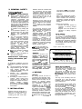
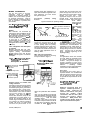
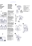
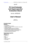
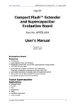
SIEMENS
GENERAL INSTALLATION GUIDE
for Siemens Solar Electric Modules
1. INTRODUCTION
This Guide contains application and
safety information with which you
should be familiar before using your
Siemens Solar photovoltaic modules.
authorized Siemens Solar
Your
distributor or dealer can provide
additional sizing and system design
information if necessary.
assemblies. All modules come with a
permanently attached junction box that
will accept a variety of wiring
applications or with a special cable
assembly for ease of installation.
411
instructions should be read
understood
before
snd
mttempting to install, wire,
maintain
the
Dperate
and
photovoltaic module.
Contact
with electrically active paris of
the module such as terminals
can result in burns, sparks, and
lethal shock whether the module
is connected or disconnected.
Since the use of this Guide and the
conditions or methods of installation,
operation, use and maintenance of the
module are beyond Siemens Solar
control, Siemens Solar does not
assume responsibility and expressly
disclaims liability for loss, damage, or
expense arising out of or in any way
connected with such installation,
operation, use or maintenance. No
responsibility is assumed by Siemens
Solar for any infringement of patents or
other rights of third parties which may
result from use of the module.
Photovoltaic modules produce
electricity when sunlight or
other sources illuminate the
front face. The voltage from a
single module is not considered
a shock hazard. When modules
are connected in series, voltages
are additive. When modules are
connected in parallel, current is
additive. Consequently, a multimodule system can produce high
voltages and current which
constitute an increased hazard
and could cause serious injury 01
death.
No license is granted by implication or
otherwise under any patent or patent
rights. The information in this Guide is
based on Siemens Solar knowledge
and experience and is believed to be
reliable; but such information including
specifications
(without
product
limitations) and suggestions do not
constitute a warranty, expressed or
implied. Siemens Solar reserves the
right to make changes to the product,
specifications, or Guide without prior
notice.
The installation of solar modules
requires a great degree of skill and
should (if DC voltage exceeds IOOV:
must) only be performed by a qualified
including,
professional,
licensed
without limitation, licensed contractors
and licensed electricians. The installer
assumes the risk of all injury that might
occur during installation, including,
without limitation, the risk of electric
shock. Siemens Solar modules do not
require the use of special cable
Part No. (019831) REV. E
l
WARNING
Disclaimer of Liability
General Information
.
.
.
.
.
.
.
.
.
.
CA UT/O/W
.
Avoid electrical hazards when
installing, wiring, operating and
maintaining the module.
A phofovolfaic module generates
DC electricity when exposed to
sunlight or other light sources.
When installing or working with
module or wiring, cover module
face completely with opaque
m a t e r i a l to halt production of
electricity.
If i s r e c o m m e n d e d t h a t t h e
module remains packed in the box
until time of installation.
Do not touch terminals while
module is exposed to light or
during
installation.
Provide
suitable guards to prevent contact
with 30VDC or greater.
As an
added precaution, use properly
insulated tools only.
Do not drop module or allow
objects to fall on module.
Do not stand or step on module.
It must be assured that other
components do not
system
generate any hazard of any
mechanical or electrical nature to
the module.
Since sparks may be produced, do
where
not
install
module
flammable gases or vapors are
present.
Never
leave
a
module
unsupported or unsecured. If a
module should fall, the glass can
A module with broken
break.
glass cannot be repaired and must
not be used.
Work only under dry conditions,
with dry module and tools.
Module installation and operation
should be performed by qualified
personnel on/y. Children should
not be allowed near the solar
electric installation.
If not otherwise specified, if is
recommended that requirements
of the latest local, national or
codes be
regional
electric
followed,
Use module for its intended
function only. Follow all module
manufacturer’s instructions. Do
not dis-assemble the module, or
remove any part or label installed
by the manufacturer. Do not treat
the back sheet with paint or
adhesives.
Do not artificially concentrate
sunlight on the module.
Retain this instruction booklet for
future reference.
The word “module” as used in
this Guide refers to one or m o r e
photovoltaic modules.
1
2. GENERAL SAFETY
Follow All Permit,
Ins talla tion and
Inspection Requirements
.
.
.
.
.
.
Before installing module, contact
appropriate
authorities to
determine permit, installation and
inspection
requirements
that
should be followed. This should
be done not only for installations
in conjunction with buildings, but
also for marine and motor vehicle
applications for which additional
requirements may apply.
Electrically ground module(s) for
all systems of any voltage (US
only).
If not otherwise specified, it is
recommended that the latest
National
and
International
Electrical Code requirements be
followed.
For roof mounted modules,
special construction m a y b e
required to help provide proper
installation. Both roof construction
and module installation design
have an effect on the fire
resistance of the
building.
Improper
installation
may
contribute to hazards in the event
of fire. Additional devices such as
ground
fault,
fuses
and
disconnects may be required.
Do not use modules of different
configurations
in the
same
system.
Follow all safety precautions of
other used components.
Underwriters Laboratory
Listing Information (US
Only):
To satisfy the conditions of the UL
Listing when installing the modules, be
sure to:
1. Use only stranded or solid copper
single-conductor type UF cable,
rated sunlight
resistant, for
modules and module wiring that
is exposed to weather.
2.
Observe
the
requirements
described by note under Electrical
Characteristics.
3. Grounding of module frame is
required.
When ground wires
greater than No. 10 AWG are
required, the installer will need to
provide
suitable
terminal
connectors to interface with the
No.10 binding screw provided with
each module.
3. INSTALLATION
Modules should be firmly fixed in
place in a manner suitable to
withstand all expected loads,
including wind and snow loads.
Part No. (019831) REV. E
Modules should be mounted with
the orientation and tilt angle
required for optimum performance
(seasonally, yearly). The location
should be selected to prevent even
partial shading from 9:00 a.m. to
3:00 p.m. (solar time) on the
shortest day of the year.
Generally, the tilt angle can be
calculated by using the site latitude
plus 20 degrees, with modules
facing south in the northern
latitudes and north in the southern
latitudes.
The mounting structure must
withstand all snow and wind forces.
Mounting holes are provided for
easy installation
and
proper
mechanical loading. Do not drill
additional mounting holes in the
module frame as it will void the
warranty.
The use of proper
mounting
hardware
is
recommended to minimize the
possibility of corrosion of the
module frame, mounting structure
and hardware. Installing a laminate
(module
without frame)
use
Siemens module clamps.
Contact
your local dealer for
. _
lntormation reaardina sDecial
mounting
irofilei -’ -for
modules and laminates.
-CR junction box - Do not connect
more than four modules in parallel.
Caution
Most of the module types contain
factory installed bypass diodes. If
these modules are incorrectly
connected to a battery, the bypass
diodes and junction box may be
damaged.
Observe correct polarity:
.
Positive wire from module to
regulator or battery positive
terminal
.
Negative wire from module to
regulator or battery negative
terminal
Array Wiring
The term “array” is used to describe
the assembly of several modules on a
support structure with associated
wiring. Use copper wire that is sunlight
resistant and is insulated to withstand
the maximum possible system open
circuit voltage. Check your local codes
for requirements.
Figure 8 Series and parallel wiring
Series wiring will increase voltage
Caution
Clearance between the
module frame and the
mounting
surface is
required to allow cooling
air to circulate around the
back of the module. This
also
all0 ws
any
condensation or moisture
to dissipate. The module
should never be sealed to the
mounting surface with sealant
that
prevents
air
from
circulating under the module.
4. WIRING
General
All wiring should be done in
accordance with applicable codes.
Wiring should be protected to help
ensure personal safety and to
prevent
its
damage.
Wiring
connectors should be mechanically
and
electrically
sound.
For
connection to a battery, we
recommend the use of a charge
regulator (except SM46 and SM20).
All modules connected in series
should be of the same model
number/type. However, modules of
different model numbers/types may
be connected in parallel (see figure
8). Modules with the ProChargerTM
Parallel wiring will increase current
Earth Ground Wiring
Each framed module has a hole in the
side frame rail for connection of a
ground wire. A No. IO binding screw
and washer is provided with each
module (not included with the
SM110/SM100 module) to connect a
ground wire to the module metal
frame.
US only: This assembly must be
performed for a safe and proper
installation. Other accessories provided
are for optional use.
To install ground wire, first install screw
with cup washer partially into hole. If
the wire is insulated, strip insulation
back approximately 5/8” (16mm) from
the end of the wire and wrap wire
around screw between its head and the
cup washer. Tighten screw. The cup
washer may be omitted if the wire is
provided with a terminal lug.
The
ground wire should also be attached to
the support structure.
2
Module Terminations
The are four types of terminal
electrical
enclosures
used
for
connections on Siemens modules. In
addition, wire is also used to provide
for electrical connections.
Refer to
figures 1 through 7 to determine which
type of connection is provided with
your module.
4.1 Wiring Modules with a
Single ProChargerTM-CR
Junction Box
General
Wire terminals are accessible by
removing the j-box lid. Remove the lid
by loosening its two captive screws
with a small flat or Phillips screwdriver.
Wire size must range from 1.5 mm2 to
10 mm2 (8 AWG to 14 AWG). The use
of wire lugs is not required or
recommended, but is possible. Once
wiring is complete, install the j-box lid
and tighten both screws to 0.5 - 0.7 Nm
(4 - 6 in-lb).
J-box configuration and description
of terminals
Modules equipped with one j-box,
contain terminals for both positive and
user-selectable
negative
polarity,
6V/l2V voltage wiring and by-pass
diodes. Refer to Figure 1 for terminal
description.
Figure 1 - Modules with Single
ProChargerTM -CR J-Box
Description of Terminals
Internal wiring terminals with:
- connection to solar cells
- bypass diodes
- jumper(s)
See figure 9 for voltage selection
stripped wire into knockout hole and
pierce through foam seal. An awl or
other sharp tool can be used to pierce
Feed
through the foam seal.
appropriate length of wire to reach
User-interface
wiring
terminal screw. Insert stripped wire
(external)
between terminal plate and square
terminals
screw
washer.
Figure 9 Selection of operating voltage
Tighten screw to
2.3 Nm 120 in-lb).
mounting posts after completion of a
repair. The schematics engraved in this
cover remind the user of the correct
wiring for 6V options.
Liquid-tight
I/2”
fitting
(NPT 4”)
Remove knockout plug with
screw-driver
placed close to
perimeter
rim
Bypass diodes not required
impact
and
driver
with
hammer. Use of
The j-box provides six IO-32 terminal
a UL recognized liquid-tight l/2” fitting
screws for external wiring of the
is required to seal and strain relief the
module. Two terminals are dedicated
wire/cable installed. Follow the fitting
to each polarity (with the polarity
manufacturer’s recommendations for
symbols engraved into the j-box floor).
installation and use. Install fitting on
Two spare terminals (i.e. floating, not
box but leave it loose. Feed the wire
connected to the module circuit) can be
through fitting and route it to terminal
used for other applications such as
screw.
Connect wire as described
blocking diodes.
above.
Complete tightening of the
liquid-tight fitting.
Wire entry and connections
There are three methods of wire entry
Conduit
to the j-box. Refer to Figure 2.
For applications where wire conduits
are used, follow the applicable codes
for outdoor installation of wires in
Figure 2 - Wire Feedconduits. Verify that all fittings are
through Options
properly installed to secure wires
ProChargerm -CR J-Box
against damage and prevent moisture
Following
conduit
intrusion.
installation and wire length adjustment,
connect wire as described above.
3ypass diodes
note direction)
12V jumper
/
6V jumpers provided in installation kit
(jumpers must not touch each other)
Strain Relief
No additional wire strain relief is
required. However, it is recommended
that strain relief be used to secure the
wire or cable to the j-box. Two posts
are provided to accept cable ties for this
purpose.
User-interface terminals with:
- (2) positive terminals (+I
- (2) negative terminals (-1
- (2) isolated or spare term
Internal wiring of module and
voltage selection
Terminals for internal wiring of module
and voltage selection are adjacent to
the slotted opening at the j-box bottom
and protected with a small cover.
These terminals are factory-wired with
interconnection to the solar cell ribbons
and by-pass diodes for 12 V D C
User does not need to
operation.
access these terminals, except for the
replacement of a broken diode or to
change the operating voltage of the
module. Figure 9 describes the wiring
for selecting the desired operating
voltage. The cover is a diode shield
and must be placed back on its
Part No. (019831) REV. E
1 f2” Liquid
tight fitting
Direct wire penetration with elastomer
seal
Only one wire should be fed through
each small diameter knockout. Remove
knockout plug with screwdriver using
Slide the rubber
moderate impact.
foam seal in the cavity in front of the
knockouts and push it down and flat all
the way with a screwdriver. Strip wire
insulation to 16mm (5/8”). Insert the
4.2 Wiring Modules with
Two ProChargerTM-CR
Junction Boxes
Modules equipped with two
separate weather-protection jcontain
terminals for
boxes
electrical connections. One j-box
output
positive
houses the
connections and the other j-box
houses the negative output
Both j-boxes also
connections.
include by-pass diodes. Refer to
figure 3 for terminal description.
3
Figure 3 - Modules with two
ProChargerTM -CR J-Boxes
Figure 4 - Modules with Single
ProChargerTM -S J-Box
Positive J-Box
through strain relief and under marked
terminal screw slider. Check the correct
polarity of wire and terminal. Tighten
screw securely using a screwdriver of
the proper size and check if it’s fixed.
Use proper wrench to tighten the strain
relief. When completed verify that the
strain relief is secured correctly by
pulling the cable.
Upon completion of wiring, set the
terminal lid in place and tighten all 4
screws. The special design of the cover
eliminates the need for a gasket. Do
not attempt to seal lid to box.
Wire entry and connections
Refer to section 4.1 “Direct Wire
Penetration with Elastomer Seal”.
4.4 Wiring Modules with
Two ProChargerm -S
Junction Boxes
Negative J-Box
Modules equipped with two
separate weather-protection jcontain terminals for
boxes
;:;r-sat yh;nections. One j-box
positive
output
connections and the other j-box
houses the negative output
connections.
Both j-boxes also
include by-pass diodes. Refer to
figure 5 for terminal description.
Figure 5 - Modules with
two ProChargerTM -S JBoxes
4.6 Wiring Modules with
One Sp Junction Box
There is one weather protected
terminal cover for positive and negative
termination. Access to the terminal
cover is obtained by unscrewing the 4
screws of the lid. The terminal has
provision for attaching one wire for
each polarity, which can range from 1.5
mm2 to 4 mm2 (12 to 16 AWG) in size.
Connect wires as described above.
4.7 Wiring Modules with
Wire or Cable Termination
Crimped connectors are recommended.
if
Wires
should be
soldered
connections are made by splicing wires
together. Connections should be
protected against corrosion and shortcircuiting.
Warning
The voltage from a single module
is not considered a shock hazard.
Do not install two or more modules
in series to make higher voltages.
Wire entry and connections
There are three methods of wire entry
to the j-box. Refer to Figure 2.
4.3 Wiring Modules with a
Single ProChargerTM -S
Junction Box
General
Refer to section 4.1 “General”.
J-box configuration and
description of terminals
Modules equipped with one j-box,
contain terminals for both positive and
negative polarity. Refer to Figure 4 for
terminal description.
Part No. (019831) REV. E
Wire entry and connections
section
“Direct
Wire
Refer to
Penetration with Elastomer Seal”.
4.5 Wiring Modules with
Two Sp Junction Boxes
There are two weather protected
terminal covers, one for positive
termination and one for negative
termination. Access to the terminal
cover is obtained by unscrewing the 4
screws of the lid. Each terminal has
provision for attaching one wire, which
can range from 1.5 mm2 to 4 mm2 (12
to 16 AWG) in size. To install wire, first
strip insulation back 16mm (5/8”). Do
not lubricate wire. Insert stripped wire
These small solar modules are
designed for 12-volt systems only.
Suggested wire sizes and lengths are as
follows (longer distances require larger
size wire):
Model
Distance
Wire Size
SM6/ST5
up to 25 feet
SMlO/STlO up to 25 feet
AWG 18
AWG 16
SM20/ST20 up to 25 feet
AWG 14
4.8 Self-Regulation
This information applies to modules
with 30 solar cells in series (SM20 and
SM46).
4
In operation, the charging current
provided to the battery by this module
decreases as the battery voltage
increases; thus, a battery at a low state of
charge will accept more charging current
than one which is at or near a full state of
charge, If the system is used during the
will
charging
current
the
day,
continuously adjust to replace the energy
used.
To obtain the benefit of self-regulation:
Use proper minimum battery size of
1.
IOOAH for each module.
2.
Install the module and battery so that
the air temperatures around them
are similar; within 20°F (-7°C).
Use the system regularly.
The
3.
current from a self-regulating
module to a fully charged battery
may overcharge the battery if the
system is not used frequently. The
amount of overcharge may result in
undesirable
consumption
of
electrolyte, but should not damage
the batfefy.
The factory-installed diodes provide
proper circuit protection without the need
for additional diodes in most systems. If,
however, it is necessary to parallel
modules within series strings, proceed as
follows:
Connect modules in parallel with internal
bypass diodes intact and place one large
external diode around the parallel group.
Each external bypass diode should be
properly rated and provided with a heat
sink, if necessary. The external diode is
required because the small internal diodes
may not share current flow equally with
this wiring arrangement.
6. MAINTENANCE
Minimal maintenance is required to
maintain optimal module performance. If
the module becomes dirty, a reduction in
We
energy output
may result.
recommend the use of water and a soft
cloth or sponge to clean the glass module
surface. A mild non-abrasive detergent
may be used on persistent contaminants.
We recommend a semi-annual inspection
electrical
mechanical
of
and
all
connections for cleanliness, tightness and
absence of damage. Protect yourself
against possible electric shock during
maintenance. Have a professional correct
any problems found.
Modules with Wire or Cable Termination
Figure 6 Diode placement and polarity
If it is not possible to meet these
requirements, it will be necessary to use a
charge regulator.
nma to protact
5. DIODES
Load
I!?
Blocking Diodes
Load
These devices prevent current flow from
the battery to the solar module when the
module is not generating electricity.
The use of blocking diodes, such as a
Schottkys barrier type, is recommended in
most applications where diodes are
required. We also recommend the use of
a charge controller.
The controller
normally has circuitry to prevent reverse
current, while protecting the battery
When using a
against overcharging.
charge controller, a blocking diode may
not be required. Contact your authorized
Siemens Solar distributor or dealer for
proper diode type. Refer to the wiring
diagram (figures 6 & 7) for diode
placement and polarity.
Black
Figure 7 ‘Controller/regulator placement
Bad
1
Bypass Diodes
Shading of individual cells and modules in
series strings can cause a reverse voltage
Because
across the cell or module.
current is forced through the shaded area
by other series cells, undesirable heating
can occur. The use of a diode to bypass
the shaded area can minimize both
heating and reduction of array current. All
Siemens modules with the exception of
the SM6, SMIO, SM20, ST5, STIO, ST20
and SRSO-Z incorporate factory installed
bypass diodes.
Part
-J
I
FUBS to protect bad
Fuse
>
+
Battery
.
Black
NO. (019831) REV. E
5
____
-
-
7. LIMITED WARRANTY
SIEMENS SOLAR ELECTRIC
(PHOTOVOLTAIC 1 MODULES
Limited Warranty - One Year Repair,
Replacement or Refund Remedy
Siemens Solar warrants the modules to
be free from defects in materials and
workmanship
normal
under
application,
installation, use and
service conditions. If the product fails
to conform to this warranty, then for a
period ending twelve (12) months from
date of sale to the original consumer
purchaser, Siemens Solar will, at its
option, either repair or replace the
product, or refund the purchase price.
The repair or replacement or refund
remedy shall be the sole and exclusive
remedy provided under the warranty
and shall not extend beyond the twelve
(121 month period set forth herein.
Limited Warranty
- Limited Remedy
For modules ST5, STIO, STZO, ST40:
If, within five (5) years from the date of
sale
to the
original
consumer
purchaser, any module(s) exhibits a
power output less than 90% of the
minimum power specified at time of
delivery, then, provided that such loss
in power is determined by Siemens
Solar (at its sole and absolute
discretion) to be due to defects in
materials or workmanship, Siemens
Solar will replace such loss in power by
either providing to the buyer additional
modules to make up the total wattage
loss, or by repairing or replacing the
module, at the option of Siemens Solar.
Limited Warranty - Limited Remedy
For modules SM6, SMlO, SM20, SP18,
SP36, SM46, SMSO-H, SM50, SR50,
SR50-Z, SM55, SMIOO, SMIIO, SM130,
SP65, SP70 and SP75, SR90, SRIOO:
If, within ten (IO) years from the date of
sale
to the original
consumer
purchaser, any module(s) exhibits a
power output fess than 90% of the
minimum power specified at time of
delivery, then, provided that such loss
in power is determined by Siemens
Solar (at its sole and absolute
discretion) to be due to defects in
materials or workmanship, Siemens
Solar will replace such loss in power by
either providing to the buyer additional
modules to make up the total wattage
loss, or by repairing or replacing the
module, at the option of Siemens Solar.
For modules SM46, SMSO-H, SM50,
SR50, SM55, SR90, SRlOO, SMIOO,
SMI 10, SM130, SP65, SP70 and SP75:
If, within twenty-five (25) years from the
date of sale to the original consumer
Part No. (019831) REV. E
purchaser, any module(s) exhibits a
power output less than 80% of the
minimum power specified at time of
delivery, then, provided that such loss
in power is determined by Siemens
Solar (at its sole and absolute
discretion) to be due to defects in
materials or workmanship, Siemens
Solar will replace such loss in power by
either providing to the buyer additional
modules to make up the total wattage
loss, or by repairing or replacing the
module, at the option of Siemens Solar.
T h e r e m e d y set forth in these
paragraphs shall be the sole and
exclusive remedy provided under the
extended term warranty. The limited
warranties set forth herein do not apply
to any module which in Siemens
Solar’s sole and absolute judgment has
been subjected to misuse, neglect or
accident, or which has been damaged
through abuse, alteration, improper
application, or
installation or
negligence
in
use,
storage,
transportation or handling, or has been
repaired, or in any way tampered with
by anyone other than Siemens Solar.
The limited warranties do not cover any
transportation costs for return of
module, or for reshipment of any
repaired or replaced module, or cost
associated with installation, removal or
reinstallation of modules.
“THE LIMITED WARRANTIES SET
FORTH HEREIN ARE EXPRESSLY IN
LIEU OF AND EXCLUDE ALL OTHER
EXPRESS OR IMPLIED WARRANTIES,
INCLUDING BUT NOT LIMITED TO
WARRANTIES OF MERCHANTABILITY
AND OF FITNESS FOR PARTICULAR
PURPOSE, USE, OR APPLICATION,
AND ALL OTHER OBLIGATIONS OR
LIABILITIES ON THE PART OF SIEMENS
SOLAR,
UNLESS SUCH OTHER
WARRANTIES,
OBLIGATIONS OR
LIABILITIES ARE EXPRESSLY AGREED
TO IN WRITING SIGNED AND
APPROVED BY SIEMENS SOLAR.
SIEMENS SOLAR SHALL HAVE NO
LIABILITY
RESPONSIBILITY OR
WHATSOEVER FOR DAMAGE OR
INJURY TO PERSONS OR PROPERTY,
OR FOR OTHER LOSS OR INJURY
RESULTING FROM ANY CAUSE
WHATSOEVER ARISING OUT OF OR
RELATED TO
THE
PRODUCT,
INCLUDING, WITHOUT LIMITATION,
ANY DEFECTS IN THE MODULE, OR
FROM USE OR INSTALLATION. UNDER
SHALL
NO
CIRCUMSTANCES
SIEMENS SOLAR BE LIABLE FOR
INCIDENTAL, CONSEQUENTIAL OR
SPECIAL DAMAGES, HOWSOEVER
CAUSED.
SIEMENS SOLAR’S AGGREGATE
LIABILITY, IF ANY, IN DAMAGES OR
OTHERWISE, SHALL NOT EXCEED THE
PAYMENT, IF ANY, RECEIVED BY
SELLER FOR THE UNIT OF PRODUCT
OR SERVICE FURNISHED OR TO BE
FURNISHED, AS THE CASE MAY BE,
WHICH IS THE SUBJECT OF CLAIM OR
DISPUTE.
SOME STATES DO NOT ALLOW
ON
IMPLIED
LIMITATIONS
WARRANTIES OR THE EXCLUSION OR
LIMITATION OF DAMAGES, SO THE
ABOVE LIMITATIONS OR EXCLUSIONS
MAY NOT APPLY TO YOU.”
Obtaining Warranty Performance
Fill out and return the Warranty
Registration Card, if supplied with the
module, within thirty (30) days after
purchase. Failing to return the card will
not affect your rights under the
warranty so long as you can establish
the date on which you purchased the
module.
If you feel you have a claim covered by
warranty, you must immediately notify
the dealer who sold you the module or
Siemens
Solar
authorized
any
distributor of the claim. Check local
telephone listings for location.
The
dealer or distributor will give advice on
handling the claim. If further assistance
is required, write Siemens Solar for
instructions.
The return of any modules will not be
accepted by the factory unless prior
written authorization has been given by
Siemens Solar.
Severability
If a part, provision or clause of the
terms and conditions of sale, or the
application thereof to any person or
circumstance, is held invalid, void or
unenforceable, such holding shall not
affect and shall leave all other parts,
provisions, clauses or applications of
the terms and conditions remaining,
and to this end the terms and
shall
be
treated
as
conditions
severable.
Disputes
No action, regardless of form, arising
out of or in any way connected with the
products or services furnished by
Siemens Solar, may be brought by the
customer or purchaser more than one
(I) year after the cause of action has
accrued.
THIS WARRANTY GIVES YOU SPECIFIC
LEGAL RIGHTS; AND YOU MAY ALSO
HAVE OTHER RIGHTS THAT VARY
FROM STATE TO STATE.
Force Majeure
Neither party shall be in any way
6
responsible or liable to the other party,
or to any third party, arising out of
nonperformance or
delay
in
performance of the terms and condition
of sale due to acts of God, war, riots,
Part No. (019831) REV. E
strikes, unavailability of suitable and
labor, material, die, or
sufficient
capacity or technical or yield failures
and any unforeseen event beyond its
control, including, without limitations,
any technological or physical event or
condition which is not reasonably
known or understood at the time of
sale.
7
Siemens Solar GmbH
Siemens Solar Industries
Siemens Showa Solar Pte. Ltd.
A joint venture of Siemens AG and Bayernwerk AG
Postfach 46 07 05
D-80915 Miinchen
Germany
Tel:
49-89-636-59-158
Fax:
49-89-636-59- 173
PO. Box 6032
Camarillo, CA 93011, U.S.A.
Tel: 805-482-6800
Fax: 805-388-6395
Web site: www.siemenssolar.com
E-mail: [email protected]
166 Kallang Way
Singapore 349249
Tel: 65-842-3886
Fax: 65-842-3887
Part No. (019831) REV. E