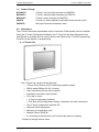
1
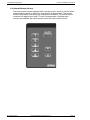
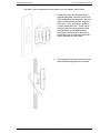
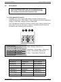
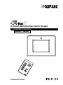
C-Touch Monchrome Touch Screen
Installation Instructions
5000CT Series
REGISTERED PATENT
Intelligent Building Series
C-Touch Installation Instructions
Table of Contents
Section........................................................................................................................Page
1.0
Product Range .................................................................................................... 3
2.0
Description ........................................................................................................... 3
2.1 C-Touch Unit ....................................................................................................... 3
2.2 Infrared Remote Control........................................................................................4
3.0
Definitions ............................................................................................................. 5
4.0
Installation Procedure ........................................................................................... 6
4.1 Installation Location .............................................................................................. 6
4.2 Installing Multiple C-Touch Controllers.................................................................. 6
5.0
Mounting Instructions ............................................................................................ 7
5.1 Wall Box ................................................................................................................ 8
5.2 Mounting Bracket .................................................................................................. 8
6.0
Wiring Details...................................................................................................... 12
6.1 C-Bus Network Connection................................................................................. 12
7.0
C-Bus System Clock........................................................................................... 13
8.0
C-Bus Power Requirements................................................................................ 13
9.0
Power-Up Load Status ........................................................................................ 13
10.0
Power Surges and Short Circuit Conditions ....................................................... 14
11.0
Megger Testing.................................................................................................... 14
12.0
Important Notes .................................................................................................. 14
13.0
Programming Requirements ............................................................................... 14
14.0
C-Touch Configuration Software ......................................................................... 14
15.0
Important Warning...............................................................................................14
16.0
Unit Operation ..................................................................................................... 15
17.0
Specifications ...................................................................................................... 15
18.0
Standards Complied............................................................................................18
19.0
Limited Warranty ................................................................................................. 18
20.0
Further Information ............................................................................................ 20
Copyright Notice
© Copyright 2003 Clipsal Integrated Systems Pty Ltd. All rights reserved.
Trademarks
Clipsal is a registered trademark of Gerard Industries Pty Ltd.
C-Bus and C-Bus2 are a registered trademark of Clipsal Integrated Systems Pty Ltd.
Scene Master is a registered trademark of Clipsal Integrated Systems Pty Ltd.
Intelligent Building Series is a registered trademark of Clipsal Integrated Systems Pty Ltd.
All other logos and trademarks are the property of their respective owners.
Disclaimer
Clipsal Integrated Systems Pty Ltd reserves the right to change specifications or designs
described in this manual without notice and without obligation.
© Copyright 2003
Clipsal Integrated Systems Pty Ltd.
Page 2
Intelligent Building Series
1.0
C-Touch Installation Instructions
Product Range
SC5000CT
C-Touch, slim line style (includes one 5035TX)
BS5000CT
C-Touch, stainless steel (includes one 5035TX)
BB5000CT
C-Touch, brass (includes one 5035TX)
5035TX
C-Touch (or Scene Master) hand held infrared remote control.
5050CTS
Neo-style Surround (Accessory Item)
2.0
Description
The C-Touch unit allows sophisticated control of an entire C-Bus system from one location.
Using the C-Touch Configuration Software, the C-Touch unit can be configured to look
and operate in whatever manner most suits the user. Refer to the C-Touch Programming
Guide for further details on programming.
2.1 C-Touch Unit
The C-Touch unit comes with the following* :
•
C-Touch Touch Screen (LCD covered by protection sheet)
•
RS232 cable (DB9 to RJ-45), 2 metres
•
User instructions (A5 full colour booklet)
•
Installation instructions (this booklet)
•
CD in slip-in cover :
• C-Touch configuration software
• PDF files of the configuration manual, installation and user instructions
*
•
The C-Touch configuration software CD.
•
Software licence agreement
•
Warranty and registration card
•
Remote Control (5035TX)
•
2 x mounting screws (finish to suit Touch Screen style) in polybag.
Subject to change without notice.
© Copyright 2003
Clipsal Integrated Systems Pty Ltd.
Page 3
Intelligent Building Series
C-Touch Installation Instructions
2.2 Infrared Remote Control
The touch screen comes equipped with a remote control, which is used to select
scenes and turn loads on and off or ramp them to a desired level. The remote
control functionality is set up by the Configuration Software. The remote control
functions will depend upon how C-Touch is programmed. If multiple touch
screens are installed, the same remote control can talk to each of them.
© Copyright 2003
Clipsal Integrated Systems Pty Ltd.
Page 4
Intelligent Building Series
3.0
C-Touch Installation Instructions
Definitions
The following definitions are useful in discussing the C-Touch unit:
Term
Definition
Load
A load is an electrical device connected to mains voltage via a C-Bus Output Unit. Most loads
are lights, but may be any device such as sprinklers, AC Power points, heaters, projection
screens, motors etc.
Group Address
This is the C-Bus designation for an output channel. It could represent one or more loads.
Scene
A scene is defined as the setting of a combination of various loads to different levels. The scene
can be set up with the configuration software and assigned to soft keys on the C-Touch unit.
Fade Rate
The fade rate indicates the length of time it takes for a load to ramp to a desired level.
Zone
Refers to an illuminated area. In C-Touch a zone is a C-Bus Group Address representing one
or many loads connected to a C-Bus Output Unit. All the lights in your dining room might be in
one zone.
Schedule
A schedule is a sequence of events that are to occur at particular times or dates in the future.
Soft Key
An area on the surface of C-Touch which can be pressed to cause something to happen.
Page
A page is an assortment of soft keys and graphics that represents something understandable
to the user.
Component
A graphical object displayed on a C-Touch screen. Components include soft keys, images, text,
clocks, temperature sensors and other items.
Backlight
The back of the screen is illuminated to make it visible when it is dark. This illumination
is called backlight.
Input Unit
An input unit is a C-Bus unit which the user interacts with to make things happen on a C-Bus
Network (C-Touch itself, a key input unit or passive infrared sensor are examples)
Output Unit
An output unit delivers power to loads; a relay and dimmer are examples.
Control
A component that can be used to turn loads on or off or change their level.
© Copyright 2003
Clipsal Integrated Systems Pty Ltd.
Page 5
Intelligent Building Series
4.0
C-Touch Installation Instructions
Installation Procedure
4.1 Installation Location
It is important to select the right location to install C-Touch.
Some considerations are listed below:
•
Provide easy access to unit for switching lights and selecting scenes
•
Avoid obstructions to receiving infrared signals from the Remote Control unit
•
Keep C-Touch clear of places subject to water, humidity, direct sunlight or
heavy dust
•
Allow adequate ventilation
•
Do not cover unit
•
C-Touch is designed for indoor use only
4.2 Installing Multiple C-Touch Controllers
Multiple C-Touch units can be installed on any C-Bus Network. These units
may be programmed to operate dependently or independently of each
other. Care must be taken not to overlap infrared reception zones for each
unit if an infrared remote control is used, or both units may trigger a scene,
with unpredictable results.
WRONG
© Copyright 2003
RIGHT
Clipsal Integrated Systems Pty Ltd.
Page 6
Intelligent Building Series
5.0
C-Touch Installation Instructions
Mounting Instructions
There are four options for mounting the C-Touch unit. These are the following:
•
Brick with Wall Box
•
Timber with Wall Box
•
Plasterboard with mounting bracket
•
Direct screwing into plugs
Each of these are described in the following sections. The screen is easiest to read when
viewed directly (straight on). The view is roughly constant up to 15 degrees below the
centre line. This illustration shows the best viewing angles. It is possible to reprogram
the touch screen for use below the horizontal viewing axis, in such a case the IR window
would be at the bottom of the screen.
15 Degrees
© Copyright 2003
Clipsal Integrated Systems Pty Ltd.
Page 7
Intelligent Building Series
C-Touch Installation Instructions
5.1 Wall Box
A C-Touch wall box (5000CTWB) is available, which allows the unit to be easily
mounted into new or existing installations. The wall box is illustrated below. This
wall box may be fitted into suitably prepared masonry or attached to a noggin
fitted between studs in a timber stud construction.
5.2 Mounting Bracket
Installation in a plasterboard wall uses the mounting bracket shown below.
© Copyright 2003
Clipsal Integrated Systems Pty Ltd.
Page 8
Intelligent Building Series
C-Touch Installation Instructions
The steps in the installation are described in the five figures which follow.
1. Prepare the wall by marking with the
supplied template. Carefully cut out the
hole indicated on the template. The hole
must not deviate beyond the range of +
3mm and – 0mm to ensure a good fit.
Loosely assemble the C-Touch unit by
inserting the two long screws through
the side holes and threading them
through the wall box. Burr the ends of
the screws over so that they cannot be
easily removed at a later date.
2. The next step is to push the top end of the
wall bracket through the hole in the wall.
© Copyright 2003
Clipsal Integrated Systems Pty Ltd.
Page 9
Intelligent Building Series
C-Touch Installation Instructions
3. Then lift the bracket in the hole and
bring the other end of the wall bracket
through the bottom of the hole. Align the
touchscreen with the cutout.
Once aligned, tighten the screws equally
until the C-Touch unit is tightly fitted to
the hole and the wall bracket is pulled
up firmly against the back surface of the
wall. Do not overtighten.
4. The cover plate can now be snap fitted
to the C-Touch unit.
NOTE: Remove protective film prior to
fitting cover.
© Copyright 2003
Clipsal Integrated Systems Pty Ltd.
Page 10
Intelligent Building Series
C-Touch Installation Instructions
5. Once fitted, the C-Touch unit should fit
flush against the front face of the wall
and the screws should bring the wall
bracket tightly against the back surface.
© Copyright 2003
Clipsal Integrated Systems Pty Ltd.
Page 11
Intelligent Building Series
6.0
C-Touch Installation Instructions
Wiring Details
Before proceeding please note: The RJ receptacle on the
back of the C-Touch unit must not be connected to C-Bus.
The connector is for the serial connection only.
6.1 C-Bus Network Connection
Installation of C-Touch on the C-Bus Network requires connection to the
unshielded twisted pair C-Bus Network Cable. Connection should be made using
Category 5 data cable, catalogue number 5005C305B.
The C-Bus Network Connection is polarity sensitive, and is clearly marked on the
rear of the C-Touch unit. Two loop-in / loop-out, removable terminal blocks are
provided for easy installation and maintenance.
Blue + Orange, C-Bus Pos (+)
Blue/White + Orange/White, C-Bus Neg (-)
Brown + Brown/White, Remote OFF
Green + Green/White, Remote ON
C-Bus Connection
Colour
C-Touch
Remote ON
Green/White
Not Connected
Remote ON
Green
Not Connected
C-Bus Neg (-)
Orange/White
C-Bus Neg (-)
C-Bus Pos (+)
Blue
C-Bus Pos (+)
C-Bus Neg (-)
Blue/White
C-Bus Neg (-)
C-Bus Pos (+)
Orange
C-Bus Pos (+)
Remote OFF
Brown/White
Not Connected
Remote OFF
Brown
Not Connected
© Copyright 2003
Clipsal Integrated Systems Pty Ltd.
Page 12
Intelligent Building Series
C-Touch Installation Instructions
WARNING: Do not connect C-Bus Network to PC comm port (RS-232).
The RS-232 serial connection (not supplied) is wired as follows:
RJ Pin
Usage
1
DCD
Meaning
Data Carrier Detect. Output from a DCE device.
2
DSR
Data set ready. Output from a DCE device.
3
DTR
Data Terminal Ready. Output from a DTE device.
Frequently used as an output from a printer to tell
the computer that its buffer is full.
4
GND
Signal Ground voltage. All signals are referenced
to this voltage. It is usually the signal ground for
the equipment's electronics.
5
RXD
Received data. Serial data flowing from a DCE
device to a DTE device.
6
TXD
Transmitted data. Serial data flowing from a DTE
device to a DCE device
7
CTS
Clear to send. Output from a DCE device.
8
RTS
Request to send. Output from a DTE device.
NOTE: We recommend you wire the C-Touch serial connector to a wall plate
(ie. Clipsal No. 2031VRJ) where it is likely that C-Touch may need to be updated
on a regular basis.
7.0
C-Bus System Clock
The C-Touch Control Unit incorporates a software selectable C-Bus System Clock used
for synchronising data communications waveforms on the C-Bus Network. No more than
three units on any C-Bus Network should have active Clock circuitry, so this option would
normally be disabled using the C-Bus Installation Software.
8.0
C-Bus Power Requirements
The C-Touch Unit draws 40mA from the C-Bus Network. Adequate C-Bus Power Supply
Units must be installed to support the connected devices. If in doubt, consult the C-Bus
Calculator – Network Design Verification Software Utility.
9.0
Power-Up Load Status
All C-Bus Units have onboard non-volatile memory, which store the operating state of
the unit in case of a C-Bus power loss. The levels will be restored by the C-Bus output
units when power is restored. C-Touch will read these levels on power up and will reflect
the current Group Address levels. Alternatively, the C-Touch unit can be configured to
enforce levels upon startup. Please refer to the Programming Guide for details.
Please refer to the C-Bus Manual for information relating to C-Bus Power Fail
Recovery Options.
© Copyright 2003
Clipsal Integrated Systems Pty Ltd.
Page 13
Intelligent Building Series
10.0
C-Touch Installation Instructions
Power Surges and Short Circuit Conditions
The mains voltage must be limited to the range specified for any C-Bus Unit which is
mains powered. Each unit incorporates transient protection circuitry, however external
power surge protection devices should be used to enhance system immunity to power
surges. It is strongly recommended that overvoltage equipment such as the Clipsal 970
is installed at the switchboard.
11.0
Megger Testing
Megger testing of an electrical installation that has C-Bus Units connected will not cause
any damage to C-Bus Units. Since C-Bus Units contain electronic components, the installer
should interpret megger readings with due regard to the nature of the circuit connection.
Megger testing must never be performed on the C-Bus data cabling or terminals as it
may degrade the performance of the Network.
12.0
13.0
Important Notes
•
An Electricians' Licence is not required to install C-Touch units.
•
Do not connect mains to C-Touch units.
Programming Requirements
The C-Touch Control Unit must be programmed to set a unique identification (Unit
Address) and the mode of operation on the C-Bus Network. The C-Bus Installation
Software can be used to configure the:
14.0
•
Unit Address
•
Clock
•
Burden
C-Touch Configuration Software
C-Touch Configuration Software is provided on CD-ROM with the C-Touch Unit. To install
the software, simply insert the CD into the CD Drive of your personal computer or laptop
and follow the on-screen prompts.
The CD-ROM also contains Online Documentation. Please refer to the C-Touch
Programming Reference for further information relating to the programming of the C-Touch.
Once the configuration of a customer installation is complete, the project should be written
to a disk and provided to the customer or archived at your premises for future reference.
15.0
Important Warning
The use of any non C-Bus Software in conjunction with the hardware installation without
the written consent of Clipsal Integrated Systems may void any warranties applicable to
the hardware.
© Copyright 2003
Clipsal Integrated Systems Pty Ltd.
Page 14
Intelligent Building Series
16.0
C-Touch Installation Instructions
Unit Operation
The many powerful features of C-Touch are fully described in the C-Touch User’s Guide.
Topics covered include:
•
Scene Selection
•
Dimming Controls
•
Using the Remote Control
•
Page Navigation
NOTE: Please consult that document for further details on the operation
of your C-Touch.
17.0
Product Specifications
Parameter
Description
Catalogue Number
5000CT Series C-Touch Control Unit
C-Bus Supply Voltage
15-36V DC @ 40mA required for normal
operation. Does not provide current to
the C-Bus Network
AC Input Impedance
50kΩ @ 1 kHz
Electrical Isolation
3.75 kV RMS from C-Bus to mains
(provided externally to 5000CT)
Control Functions
Load switching and dimming
Scenes
Schedules
Maximum number of controlled loads
255 Group Addresses on each
of 10 applications
Status indicators
User configurable
Maximum Number of C-Touch Units
on a single C-Bus Network
50
Night-light Option
(Allows permanent LED illumination at
low brightness level)
Warm Up Time
1 minute
Network Clock
Software selectable
C-Bus Connection
2 X Loop-in/Loop-out Removable
Terminal blocks provided 0.2-15mm2
(24-16 AWG) see section 6 in the
installation instructions for the pin out)
Dimensions
152 x 115 x 42mm (L x W x H)
Weight
365g
Mounting Centres
124mm
Operating Temperature Range
10-30 °C
Operating Humidity Range
10-95% R.H.
Colour
Stainless Steel, Brass, Powdercoat
© Copyright 2003
Clipsal Integrated Systems Pty Ltd.
Page 15
Intelligent Building Series
C-Touch Installation Instructions
All dimensions in millimetres.
© Copyright 2003
Clipsal Integrated Systems Pty Ltd.
Page 16
Intelligent Building Series
C-Touch Installation Instructions
5035TX Infrared Remote Control
Parameter
Description
Catalogue Number
5035TX Infrared Remote Control
Supply Voltage
3V DC required for normal operation.
Transmission range reduces with
reducing battery voltage
Battery
Lithium “Coin” Battery CR2025
(or equivalent)
Battery Shelf Life
Approximately 1 year
Infrared Transmission Range
≤15 m at 90° to C-Touch unit
Control Functions
8 membrane buttons comprising
5 general purpose buttons
1 master off button
up/down buttons
Dimensions
86 x 54 x 8mm (L x W x H)
Weight
28g
Colour
Black
85mm
Infrared Remote Control dimensions
54mm
8mm
No user serviceable parts inside.
© Copyright 2003
Clipsal Integrated Systems Pty Ltd.
Page 17
Intelligent Building Series
18.0
C-Touch Installation Instructions
Standards Complied
Standard
Title
AS/NZS 3100:1997 inc Amd. 5
General Requirements for Electrical Equipment
AS/NZS 3260:1993 inc Amd. 4
Approval and test specification – Safety of
information technology and business equipment
AS/NZS 3108:1994 inc Amd. 6
Requirements for Safety Extra Low Voltage
IEC 742: 1983 Amdt (1) IEC 60742
Am1 Ed 1.0b 1983 (Am 1992).
Isolating transformers and safety isolating
transformers - Requirements
AS/NZS 3548:1995 A1, A2
IEC/CISPR 22:1995 A1 A2
Information Technology Equipment Radio
Frequency Emissions Standard
EN 55022- 1998
IEC/CISPR 22:1997 A1
Information Technology Equipment Radio
Frequency Emissions Standard
EN 55024- 1998
CISPR 24:1997
Information Technology Equipment
Immunity Standard
EN 61000-3-2:1995 A1, A2
IEC 61000-3-2:1995 A1, A2
Harmonic Current Emissions Standard
EN 61000-3-2:1995
IEC 61000-3-3:1995
Voltage Fluctuations and Flicker Standard
EN 61000-4-2
IEC 61000-4-2
Immunity to Electrostatic Discharge
Basic Standard
EN 61000-4-3
IEC 61000-4-3
Immunity to Radio Frequency Electromagnetic
Field Basic Standard
EN 61000-4-4
IEC 61000-4-4
Immunity to Electrical Fast Transients
Basic Standard
EN 61000-4-5
IEC 61000-4-5
Immunity to Electrical Surges
Basic Standard
BS/EN 61000-4-6
Continuous Radio Frequency Emissions
89/336/EEC
European Union Directive on
Electromagnetic Computability
19.0
Limited Warranty
The C-Touch product carries a two year warranty against manufacturing defects
(refer to Warranty Statement) with the following exclusions:
Infrared Remote control
Limited to 30 day warranty on battery
condition as supplied
C-Touch Configuration software
Limited 90 day warranty on software
media only
© Copyright 2003
Clipsal Integrated Systems Pty Ltd.
Page 18
Further Information
For further information about programming and configuring C-Touch, please consult
the documentation supplied (these documents are also provided in pdf form on the
distribution disk):
•
C-Touch Installation Instructions
The printed booklet you are reading now contains detailed information for the
installer regarding unit monitoring, wiring, and C-Bus Network requirements.
C-Touch features and specifications are also presented.
•
C-Touch User's Guide
The printed booklet supplied with C-Touch, to be left on-site for the customer. It
contains information about C-Touch operation, general use and care instructions.
•
C-Touch Programming Reference
The C-Touch Programming Reference is provided on CD in electronic format
(Portable Document File (PDF), and requires Adobe Acrobat Reader v4.0 or
higher to view or print). It presents a comprehensive guide to programming
requirements and advanced configuration capabilities of C-Touch.
•
Technical Support and Troubleshooting
For further assistance in using C-Touch, please consult your nearest Clipsal
Integrated Systems Sales Representative or Technical Support Officer.
Technical Support Hotline
Technical Support Email
Sales Support Email
Clipsal Integrated Systems Website
1300 722 247 (Cost 25¢ a call)
[email protected]
[email protected]
clipsal.com/cis
Product of Clipsal Integrated Systems Pty Ltd
ABN 15 089 444 931
12 Park Terrace, Bowden, South Australia 5007
Telephone (08) 8269 0560
Facsimile
(08) 8346 0845
Internet
clipsal.com/cis
E-Mail
[email protected]
10362641