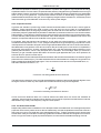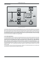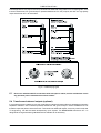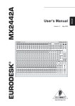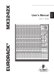
1
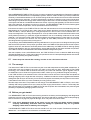
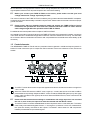
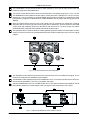
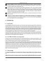
Version 1.1 November 2001 TUBE ULTRA-Q® www.behringer.com ENGLISH T1951 Users Manual TUBE ULTRA-Q T1951 SAFETY INSTRUCTIONS CAUTION: To reduce the risk of electric shock, do not remove the cover (or back). No user serviceable parts inside; refer servicing to qualified personnel. WARNING: To reduce the risk of fire or electric shock, do not expose this appliance to rain or moisture. This symbol, wherever it appears, alerts you to the presence of uninsulated dangerous voltage inside the enclosurevoltage that may be sufficient to constitute a risk of shock. This symbol, wherever it appears, alerts you to important operating and maintenance instructions in the accompanying literature. Read the manual. DETAILED SAFETY INSTRUCTIONS: All the safety and operation instructions should be read before the appliance is operated. Retain Instructions: The safety and operating instructions should be retained for future reference. Heed Warnings: All warnings on the appliance and in the operating instructions should be adhered to. Follow instructions: All operation and user instructions should be followed. Water and Moisture: The appliance should not be used near water (e.g. near a bathtub, washbowl, kitchen sink, laundry tub, in a wet basement, or near a swimming pool etc.). Ventilation: The appliance should be situated so that its location or position does not interfere with its proper ventilation. For example, the appliance should not be situated on a bed, sofa, rug, or similar surface that may block the ventilation openings, or placed in a built-in installation, such as a bookcase or cabinet that may impede the flow of air through the ventilation openings. Heat: The appliance should be situated away from heat sources such as radiators, heat registers, stoves, or other appliances (including amplifiers) that produce heat. Power Source: The appliance should be connected to a power supply only of the type described in the operating instructions or as marked on the appliance. Grounding or Polarization: Precautions should be taken so that the grounding or polarization means of an appliance is not defeated. Power-Cord Protection: Power supply cords should be routed so that they are not likely to be walked on or pinched by items placed upon or against them, paying particular attention to cords and plugs, convenience receptacles and the point where they exit from the appliance. Cleaning: The appliance should be cleaned only as recommended by the manufacturer. Non-use Periods: The power cord of the appliance should be unplugged from the outlet when left unused for a long period of time. Debris and Liquid Entry: Care should be taken that debris and/or liquids do not enter the enclosure through openings. Damage Requiring Service: The appliance should be serviced by qualified service personnel when: - The power supply cord or the plug has been damaged; or - Debris or liquid has entered the appliance; or - The appliance has been exposed to rain; or - The appliance does not appear to operate normally or exhibits a marked change in performance; or - The appliance has been dropped, or the enclosure damaged. Servicing: The user should not attempt to service the appliance beyond that which is described in the operating instructions. All other servicing should be referred to qualified service personnel. 2 TUBE ULTRA-Q T1951 FOREWORD Dear Customer, We thank you for expressing your confidence in BEHRINGER products by purchasing the BEHRINGER TUBE ULTRA-Q. It is one of my most pleasant tasks to write this preface, as our engineering team has made it possible to enhance the traditional tube circuitry design (particularly for our VINTAGER series of products), and adapt it to meet the high sound quality and dynamics requirements of modern, pro-level audio technology. The fact that we are still fascinated by antique tube radios and amps as well as the fine and warm tonal character that we usually associate with them, are the reasons why vacuum tubes have kept their ground even in state-of-the-art circuit topologies used especially in professional audio technology or high-end devices. We are particularly proud that we have found an extremely effective symbiosis between solid-state and tube technologies making them affordable to anybody interested in audio technology. As always, our top-priority concern when developing this device was the demanding end user, in other words: you. It was our major goal to meet your demands. Sure, it meant a lot of hard work to develop such a product, but the fun has made it all worthwhile. The shine in the eyes of the many interested musicians at the Music Fair 1997, when they saw our VINTAGER models for the first time, was a lasting incentive driving our development efforts. It is our philosophy to share our joy with you, because you are the most important member of the BEHRINGER family. With your highly competent suggestions for new products youve greatly contributed to shaping our company and making it successful. In return, we guarantee you uncompromising quality (manufactured under ISO9000 certified management system) as well as excellent technical and audio properties at an extremely favorable price. All of this will enable you to fully unfold your creativity without being hampered by budget constraints. We are often asked how we can make it to produce such high-grade devices at such unbelievably low prices. The answer is quite simple: its you, our customers! Many satisfied customers means large sales volumes enabling us to get better conditions of purchase for components, etc. Isnt it only fair to pass this benefit back to you? Because we know that your success is our success, too! I would like to thank all people whose help on Project TUBE ULTRA-Q has made it all possible. Everybody has made very personal contributions, starting from the designers of the unit via the many staff members in our company to you, the user of BEHRINGER products. My friends, its been worth the trouble! Thank you very much, Uli Behringer 3 TUBE ULTRA-Q T1951 TUBE ULTRA-Q® 2 x 4-Band Parametric Tube Equalizer T1951 s 4-band parametric stereo equalizer with selected 12AX7 tubes s ULTRA-TUBE circuitry (UTC) adds desired amount of warmth without additional noise s Parallel filter architecture ensures minimal phase shifting s Precision state-variable filters with constant-Q characteristic s Ultra low-noise 4580 audio operational amplifiers offer outstanding performance s Switchable shelving filter functions remove unwanted frequencies s Each band can be bypassed and is fully adjustable from notch filter to broadband equalization s Broad frequency band overlapping allows extreme boost/attenuation s High-quality detented potentiometers and switches with vintage-style knobs s Cut-in delay to avoid switch-on thumps s Relay-controlled hard bypass with auto bypass function in case of power failure s Servo-balanced gold-plated XLR and 1/4" TRS inputs and outputs s BEHRINGERs high-performance OT-1 output transformer retrofitable s High-quality components and exceptionally rugged construction ensure long life even under the most demanding conditions s Manufactured under ISO9000 certified management system 4 TUBE ULTRA-Q T1951 TABLE OF CONTENTS 1. INTRODUCTION .....................................................................................................................6 1.1 The concept .................................................................................................................................... 6 1.2 Before you get started ..................................................................................................................... 6 1.3 Control elements ............................................................................................................................. 7 2. OPERATION ............................................................................................................................9 2.1 2.2 2.3 2.4 Introduction ..................................................................................................................................... 9 The TUBE ULTRA-Q in the signal path ........................................................................................... 9 Filter settings .................................................................................................................................. 9 Setting of the tube stage ................................................................................................................ 11 3. APPLICATIONS ..................................................................................................................... 11 3.1 3.2 3.3 3.4 3.5 Filtering out unwanted frequencies ................................................................................................. 11 Shelving filters and Roll Off .......................................................................................................... 12 Equalizers as creative audio tools ................................................................................................. 12 The TUBE ULTRA-Q as tube interface ........................................................................................... 14 EQ-ing a P.A. system ................................................................................................................... 14 4. TECHNICAL BACKGROUND .............................................................................................. 16 4.1 4.2 4.3 4.4 4.5 Function ........................................................................................................................................ The Constant-Q principle ............................................................................................................. The concept of parallel filters ......................................................................................................... On phase shift and time delay ....................................................................................................... Tubes used in the TUBE ULTRA-Q ................................................................................................ 4.5.1 Tube history ........................................................................................................................ 4.5.2 Design and functional principle of tubes .............................................................................. 4.5.3 Properties of tubes .............................................................................................................. 4.5.4 The best of both worlds ....................................................................................................... 4.5.5 UTC circuit .......................................................................................................................... 4.5.6 Studio applications .............................................................................................................. 16 16 16 17 17 17 18 19 19 20 20 5. INSTALLATION ..................................................................................................................... 21 5.1 5.2 5.3 5.4 Rack mounting .............................................................................................................................. Mains voltage ................................................................................................................................ Audio connections ........................................................................................................................ Transformer-balanced outputs (optional) ........................................................................................ 21 21 21 22 6. SPECIFICATIONS ................................................................................................................. 23 7. WARRANTY ........................................................................................................................... 24 5 TUBE ULTRA-Q T1951 1. INTRODUCTION With the BEHRINGER TUBE ULTRA-Q T1951 you have purchased an innovative device. Parametric equalizers represent the most advanced form of equalization systems. With the TUBE ULTRA-Q you have purchased an extremely musical and flexible device. Our ULTRA-Q range of devices has been a hit ever since we introduced our first model some 5 years ago. This high-end parametric equalizer is based on many years of experience and findings in equalizer technology and is used throughout the world in renowned studios, sound reinforcement systems as well as in broadcast and television studios. Improving the legendary ULTRA-Q even further was a real challenge, and we are proud of our success. The BEHRINGER TUBE ULTRA-Q meets highest requirements in terms of operation, sound, specifications and workmanship. Even at the conception of the TUBE ULTRA-Q it was clear that we had to combine the outstanding technical specifications of our ULTRA-Q with a warm tube sound. We are therefore proud to be able to present the TUBE ULTRA-Q, a device featuring our newly developed UTC vacuum tube circuit combined with a nocompromise approach. The newly developed UTC circuit provides subtle sound enhancement rather than showy effects processing. In particular, digital workstations can be considerably enhanced in their sound character. You are free to use the TUBE ULTRA-Q before the recording sessions or later when you mix down the music you recorded. You can also use it to brighten up entire MIDI productions or even movie sound recordings and thus give them their finishing touch. The philosophy behind BEHRINGER products guarantees a no-compromise circuit design and employs the best choice of components. The op-amps, type 4580, used in the TUBE ULTRA-Q are chosen for their superior signal-to-noise ratio, low distortion and linear performance. Additionally, the TUBE ULTRA-Q uses high quality resistors and capacitors with very tight tolerances, high-grade switches as well other selected components. The TUBE ULTRA-Q is manufactured under ISO900 certified management system. With the exception of two 12AX7/ECC83 tubes, the TUBE ULTRA-Q T1951 is based on SMD technology (Surface Mounted Device). These subminiature components known from aerospace applications ensure both extreme packing density and greater reliability. + Please keep the manual after reading, in order to use it for future reference. 1.1 The concept The heart of the TUBE ULTRA-Q is an extremely low-noise and transparent sounding state-variable filter. In combination with the Constant-Q principle, the 4580 op-amp and the newly developed ULTRA-TUBE technology, the TUBE ULTRA-Q achieves extremely low noise and distortion figures together with an incredible warm sound. With four fully parametric bands, it offers you truly professional signal processing. In the TUBE ULTRA-Q, two selected 12AX7 / ECC83 vacuum tubes are used. These triodes are capable of handling a large dynamic range with little microphony. In addition to that their relative ruggedness and above average life span and you can see why its one of the most popular and reliable pre-amp tubes on the market. These features also ensure you their availability for many years to come. Failsafe relays have been incorporated into the design of the BEHRINGER TUBE ULTRA-Q, which automatically and silently bypass the unit in the event of power supply disconnection or failure. These relays are also active at switch-on to isolate the TUBE ULTRA-Q until the power rails have settled, thus preventing the possibility of a potentially damaging switch-on thump. 1.2 Before you get started Your BEHRINGER TUBE ULTRA-Q was carefully packed in the factory and the packaging was designed to protect the unit from rough handling. Nevertheless, we recommend that you carefully examine the packaging and its contents for any signs of physical damage, which may have occurred in transit. + If the unit is damaged, please do not return it to us, but notify your dealer and the shipping company immediately, otherwise claims for damage or replacement may not be granted. Shipping claims must be made by the consignee. The BEHRINGER TUBE ULTRA-Q fits into two standard 19" rack units of space. Please allow at least an additional 4" / 10 cm depth for the connectors on the back panel. 6 1. INTRODUCTION TUBE ULTRA-Q T1951 Be sure that there is enough space around the unit for cooling and please do not place the TUBE ULTRA-Q on high temperature devices such as power amplifiers etc. to avoid overheating. + Before you connect your TUBE ULTRA-Q to the mains, please make sure that your local voltage matches the voltage required by the unit! The mains connection of the TUBE ULTRA-Q is made by using a mains cable and a standard IEC receptacle. It meets all of the international safety certification requirements. Please make sure that all units have a proper ground connection. + Please ensure that only qualified persons install and operate the TUBE ULTRA-Q. During installation and operation the user must have sufficient electrical contact to earth. Electrostatic charges might affect the operation of the TUBE ULTRA-Q! For additional information please refer to chapter 5 INSTALLATION. As a standard, the audio inputs and outputs on the TUBE ULTRA-Q are fully balanced. If possible, connect the unit to other devices in a balanced configuration to allow for maximum interference immunity. The automatic servo function detects unbalanced connections and compensates the level difference automatically (6 dB correction). 1.3 Control elements The BEHRINGER TUBE ULTRA-Q has four parametric filters organized in 4 different frequency bands. A backlit VU meter shows the input or output level. Each channels comes with a Warmth control, and a tube window. Fig. 1.1: Control elements on the front panel 1 The INPUT control determines the input level applied to the device and can be set within a range from -15 to +15 dB. 2 When the PEAK LED above the INPUT control lights up, it means that a level of at least 18 dBu is present after the input stage. Adjust the INPUT control so that the PEAK LED lights up only with signal peaks, make sure that it never lights up all the time. When the PEAK LED is on, there is still some 5 dB of headroom left. + 3 Please note that extreme boost settings in combination with a high input level can overload the unit. In such a case, the input level must be reduced with the INPUT control. The IN/OUT switch is used to enable/disable the entire equalizer section in the audio path. The switch uses a relay-controlled hard bypass function, i.e. as long as it is not active or if the unit is switched off, the inputs are directly connected to the outputs. The IN/OUT switch allows for A/B comparisons between processed and unprocessed signals. 1. INTRODUCTION 7 TUBE ULTRA-Q T1951 4 The FREQUENCY control selects the filters center frequency, which can be freely chosen within the frequency range of the associated band. 5 The LEVEL control determines the amount of level boost/cut. The setting range is from -15 to +15 dB. 6 The BANDWIDTH control determines the slope or quality of the filter. Settings from 0.03 (Q = 43) to 2 octaves (Q = 0,67) are possible. A small bandwidth (high Q) means that the only a small portion of the total frequency range will be affected while a wide bandwidth (low Q) means that a large part will be affected. 7 With the SHELF/PEAK switch the two outer bands can be switched from parametric (peaking response) EQ to low and high pass (shelving EQ) filters respectively. Use this feature to eliminate rumble, plop and breathing noises from the bottom end and noise or hiss from the top end. When switched to PEAK mode the filters operate identical to the other filters. 8 The individual IN/OUT switches allow for enabling/disabling specific bands in the audio path. Use this switch to check the influence of the separate filters and to switch unused filters of for maximum signal integrity. Fig. 1.2: Control elements on the front panel 9 The WARMTH control determines the amount of harmonics the UTC circuit adds to the signal. This is the amount of tube sound (WARMTH) that is added. 10 The WARMTH meter displays the amount of added harmonics. This controls the amount of harmonics, or tube sound (WARMTH), the UTC circuit adds to the signal. 11 Use the POWER switch to turn the TUBE ULTRA-Q on or off. When switched of the TUBE ULTRA-Q automatically switches to a hard bypass mode, the signal is then led directly to the outputs. 12 14 13 15 Fig. 1.3: Rear panel elements of the TUBE ULTRA-Q 8 1. INTRODUCTION TUBE ULTRA-Q T1951 12 SERIAL NUMBER. Please complete and return the warranty card within 14 days of the date of purchase. Otherwise, you will lose your right to the extended warranty. Alternatively, you can register online at our website under www.behringer.com. 13 FUSE HOLDER / VOLTAGE SELECTION. Before connecting the T1951, confirm that the voltage display matches your local mains voltage. When replacing the fuse, you must always use the same type. In many units the fuse holder can be installed in one of two positions, allowing you to switch between 230 V and 115 V. If you wish to operate a unit outside Europe at 115 V, then a stronger fuse must be used (see chapter 6 SPECIFICATIONS). The mains connection is made via the IEC receptacle. An appropriate mains cable is included. 14 AUDIO IN. These are the audio inputs of your TUBE ULTRA-Q, available both as balanced 1/4" TRS and XLR connectors. 15 AUDIO OUT. These are the audio outputs of your TUBE ULTRA-Q. Matching 1/4" TRS and XLR connectors are wired in parallel. The automatic servo function recognizes balanced or unbalanced connection and automatically compensates for the difference in level (correction 6 dB). The BEHRINGER OT-1 output transformer is optionally retrofitable. 2. OPERATION 2.1 Introduction The BEHRINGER TUBE ULTRA-Q gives you a combination of all technical properties both of parametric equalizers and of narrow-band notch filters. With its excellent audio quality and outstanding specifications it is simply better than any conventional equalizer. The ULTRA-Q can be used to make up for frequency response deficiencies and to creatively process any audio material, thus giving you undreamed-of equalization flexibility. It is a highly efficient and all-purpose tool both in creative audio processing in broadcast and television studios, in video post-production and on stage. Each of its four bands can be freely adjusted in quality: from extremely narrow to broad-band. The TUBE ULTRA-Q is superior to graphic equalizers in all respects. The BEHRINGER TUBE ULTRA-Q uses our newly developed ULTRA-TUBE technology, a development resulting from two years of intensive research work by our engineering team. The ULTRA-TUBE technology overcomes the problems related to tube circuitry (see chapter 4) and generates upper harmonics even at low levels to give your recordings more warmth and power. 2.2 The TUBE ULTRA-Q in the signal path The best point to insert the TUBE ULTRA-Q in the signal path depends on the task on hand: basically, it can be inserted in the main mix insert points of your mixing console, subgroup inserts, subgroup outputs, effects paths or between signal processor(s) and mixing console/power amp, etc. Due to its 2-channel architecture, you can also insert the TUBE ULTRA-Q in two independent channels of the mixing console (if available). This way the TUBE ULTRA-Q acts as a high-quality and versatile channel EQ. Depending on the wiring of the inserts on the console, you either need a special 1/4" stereo insert cable that is routed to two mono jacks (send & return), or two separate cables for the send and return path. Connect the insert sends of the subgroups to the inputs on the TUBE ULTRA-Q, and the insert returns to the outputs. You can even connect the two channels of the TUBE ULTRA-Q in series to make one equalizer with 8 bands! Connect the output of channel one with the input of channel two. Set the output of channel one as well as the INPUT control of channel two at 0 dB. 2.3 Filter settings You may find that getting to know a dual channel processor like the TUBE ULTRA-Q is easier when you concentrate on one channel first. If you have a mixer, connect the TUBE ULTRA-Q to the insert of one channel only. Always start off by setting all controls to neutral. All gain controls at 0 dB and bandwidth wide. This prevents wasted time looking for non-existent problems or that settings with a gain higher than 0 dB cause problems 2. OPERATION 9 TUBE ULTRA-Q T1951 like feedback. In live applications uncontrolled feedback can cause damage to loudspeakers and amplifiers. By means of the INPUT control you can adapt the sensitivity of the TUBE ULTRA-Q to the input level. The sensitivity can be varied within a range of -15 to +15 dB. Set the INPUT control so that the PEAK LED lights up only rarely, it should never light up constantly. If the LED lights up it means that the level directly after the INPUT control is exceeding +18 dBu, this means that there is still approx. 5 dB headroom until the TUBE ULTRA-Q starts clipping. + + Please note that extreme levels can be achieved with this unit. When a high input level is combined with an extreme setting or multiple filters boosting the same frequency range, overloading can occur even though the input level was set correctly. This can not be contributed to a malfunctioning of the unit but is a consequence of the settings that were chosen. If this occurs please lower the input level or choose less extreme settings. If extreme equalizer settings are necessary to achieve a usable frequency response, the alarm bell should start ringing! The shelving filters In contrast to graphic equalizers with fixed frequencies and bandwidths you can freely set all filter parameters, center frequency, bandwidth and gain, with a parametric equalizer. The two outer filters of the TUBE ULTRA-Q can additionally be switched between shelving (SHELF) and bell characteristic (PEAK). In the setting SHELF the filter resembles a normal tone control on a hifi amplifier, but with the possibility to alter the start frequency and the slope of the filter. The frequency can be set within a wide range with the FREQUENCY control. With the BANDWIDTH control the slope can be altered. When the control is turned counter-clockwise the slope becomes steeper, turning the other way results in a more gentle slope. The LEVEL control sets the amount of boost or attenuation. Use the shelving filters to control rumble, plop/ breathing noises and wind or tape hiss. With the freedom to set the frequency, slope and gain, the TUBE ULTRA-Q can be tailored exactly to your needs giving you much more flexibility than any other standard low-cut switch. The parametric filters When the first and the last filters are set to PEAK, they are identical to the two other filters. In that case the filters have a peaking response or a bell curve. Start by boosting a fairly broad frequency band to locate the frequency band you want to adjust. It is easier to locate problem frequencies by boosting them first. When the problem frequency is located you can adjust the bandwidth to isolate the correct range. Now you can cut or boost this range to suit your needs. The filters are set up in such a way that they cover the entire spectrum from 20 Hz to 20 kHz, while overlapping each other over a wide range. After finding the right setting you can tweak the setting of each band to achieve maximum results. During operation you can switch on and off the individual bands to make an A/B comparison between the equalizer effect and the unprocessed signal. Due to the complex and partly difficult settings of parametric equalizers such a facility is indispensable. Still, most parametric EQs have no band-specific in/out switches which makes it difficult to keep track of what the various switches and controls do. Adjusting the overall level It is possible that you have to correct the overall level after setting the equalizer. It is possible that the effect of the filters result in a higher or lower level than the original signal. Use the INPUT control to adjust the total level. You can compare the processed and unprocessed level with the help of the IN/OUT switch. + 10 Please note that the IN/OUT performs a hardware bypass. The input signal is fed directly to the output. The INPUT control has no influence. 2. OPERATION TUBE ULTRA-Q T1951 Fig. 2.1: Various filter qualities 2.4 Setting of the tube stage With the settings you have achieved so far a considerable sound improvement can be made. You may not know this, but you have already benefitted from the tube stage of the TUBE ULTRA-Q. Even when the WARMTH control is turned fully counter-clockwise, subtle and hardly noticeable warmth and musicality is added to the signal. You can now drastically increase the effect by turning up the WARMTH control. With the tube stage featured in the BEHRINGER TUBE ULTRA-Q you can add the typical tube sound with the WARMTH control. Increasing amounts of upper harmonics generated by the new UTC circuitry are then added to the signal. This leads to more musical and transparent hights which combine perfectly with the enhancer/ exciter effect, which can perhaps even be reduced a little in favor of the warm tube sound. You can monitor the amount of WARMTH that is added with a glance at the WARMTH meter. 3. APPLICATIONS 3.1 Filtering out unwanted frequencies One of the most important tasks of the TUBE ULTRA-Q is the notching out of problem frequencies. With notching or peaking we describe the specific attenuation of single frequencies or frequency bands. A notch filter produces an effect that is the opposite of a band-pass filter. Specific frequencies or ranges can be targeted like hum, rattle or feedback frequencies. Resonance in a room or microphone can be eliminated effectively. Fig. 3.1: Typical notch function 3. APPLICATIONS 11 TUBE ULTRA-Q T1951 Because of the wide overlap possibility of the different filters, the effect of two filters can be added together if so desired. This way an even greater attenuation or boost can be achieved. When notching out frequencies try to make the band as small as possible. Always as little as possible but as much as needed. 3.2 Shelving filters and Roll Off Switching one or two of the outer filters to SHELF enables you to adapt or limit the entire frequency response. With the LEVEL control you can set the degrees of boost or attenuation, with the BANDWIDTH control the slope and with FREQUENCY control the frequency from which the slope starts. Practice has shown how important this feature is, as most acoustic problems are encountered in the extreme low and high frequency ranges. Typical frequency response, hum or feedback problems must be handled differently. The additional low and high shelving filters allow for a broad-band correction of the frequency curve, while the parametric filters can be used to process narrow frequency bands (mains hum, feedback, etc.). Fig. 3.2: Typical roll-off function With roll-off we usually refer to a limitation of frequency bands by means of high or low pass filters. If you set the LEVEL control at -15 dB, the BANDWIDTH control fully left and the FREQUENCY control somewhere between 50 and 100 Hz, you have a very steep low-cut filter. This will eliminate rumble and breathing noises very effectively without affecting the sound. At the high cut side you can reduce tape hiss for example. Use this feature with caution however to prevent the material from becoming muffled or sharp. It is advisable to use a dedicated denoiser like the BEHRINGER MULTIBAND DENOISER SNR2000 to effectively eliminate tape noise. The TUBE ULTRA-Q is well suited for in-the-field problem solving when unexpected hiss arises. 3.3 Equalizers as creative audio tools The TUBE ULTRA-Q is an indispensable audio tool for application in recording studios, stage plays or radio dramas. You can use it to distort voices, create telephone sounds and filter instruments to make them fit into the mixdown. The charts printed below give you some clues as to the acoustic significance of specific frequencies. Please use them as suggestions for your own experiments with the TUBE ULTRA-Q. 12 3. APPLICATIONS TUBE ULTRA-Q T1951 Center frequency (Hz) 1/3 octave Effects on music 31 to 63 Fundamentals of bass drum, tuba, double bass and organ. These frequencies give music a sense of power. If overemphasized they make the music "muddy". The 50 or 60 Hz band is also used to reject AC mains hum. 80 to 125 Fundamentals of lower tympani. Too much boost produces excessive "boom". 100 or 125 Hz are also used for hum rejection. 160 to 250 Drum and lower bass. Too much boost produces excessive "boom". Also useful for 3rd harmonic mains hum rejection. 315 to 500 Fundamentals of strings and percussion. 630 to 1k Fundamentals and harmonics of strings, keyboards and percussion. Boosting the 600 to 1 kHz range can make instruments sound horn-like. 1.25k to 4k Drums, guitar, accentuation of vocals, strings and bass. Too much boost in the 1 to 2 kHz range can make instuments sound tinny. Too much boost anywhere between 1 to 4 kHz can produce "listening fatigue". 5k to 8k Accentuation of percussion, cymbals and snare drum. Reduction at 5 kHz makes overall sound more distant and transparent. Reduction of tape hiss and system noise. The 1.25 to 8 kHz governs clarity and definition. 10k to 16k Cymbals and overall brightness. Too much boost causes sibilance. Reduction of tape hiss and system noise. Tab. 3.1: Effects of equalization on music reproduction 3. APPLICATIONS 13 TUBE ULTRA-Q T1951 Center frequency (Hz) 1/3 octave Effects on voice 40 to 125 Sense of power in some outstanding bass singers. 160 to 250 Voice fundamentals. 315 to 500 Important for voice quality. 630 to 1k Important for voice naturalness. Too much boost in the 315 to 1 kHz range produces a telephone-like quality. 1.25k to 4k Voice fricatives-accentuation of vocals. Important to speech intelligibility. Too much boost between 2 and 4 kHz can mask certain speech sounds e.g. "m", "b", and "v" can become indistinguishable. Too much boost anywhere between 1 and 4 kHz can produce "listening fatigue". Vocals can be highlighted by slightly boosting the vocal at 3 kHz and at the same time slightly dipping the instruments at the same frequency. 5k to 8k Accentuation of voice. The range from 1.25 to 8 kHz governs the clarity of voice. 10k to 16k Too much boost causes sibilance. Tab. 3.2: Effects of equalization on voice reproduction + Use the SHELF function to create a small lift in the upper frequencies, this is especially useful when using analog tape. Trying to recover lost brilliance is always tricky because you boost hiss as well. It is better to record bright, you can always mix back the brilliance. 3.4 The TUBE ULTRA-Q as tube interface If you want to use the TUBE ULTRA-Q purely as tube interface switch off all filters with their respective IN/OUT switches but keep the master IN/OUT switch engaged. Now you can add upper harmonics by turning up the WARMTH control. Percussive instruments gain in punch while instruments that are rich in harmonics like horns gain transparency and brilliance. Connect your TUBE ULTRA-Q via the channel or subgroup inserts of your mixer. This way you can add tube sound to selected instruments or groups of instruments. The TUBE ULTRA-Q is also very adapt to processing the entire mix. You can of course combine the tube and parametric equalizer functions of the TUBE ULTRA-Q. 3.5 EQ-ing a P.A. system Parametric equalizers can also be combined with conventional graphic equalizers. The application of both is conceivable in a P.A. system: the graphic equalizer can be used for broad-band corrections of the frequency response, for example, to simulate a tone control circuit, to adjust the sound of specific speaker systems or to enhance the low-range response and/or to make up for high-frequency loss caused by room acoustics. The TUBE ULTRA-Q can then be used for the detailed correction and the notching out of resonances. Before you insert an equalizer in your sound reinforcement system, you should clearly define its tasks. If you fail to set up the EQ properly, it might deteriorate the sound image more than if you used no sound-processing device at all. In a sound reinforcement system equalizers are used in three major areas of application: 14 1. Reducing the risk of feedback, while increasing the overall volume level. 2. Improving the natural sound of music. 3. Improving the intelligibility of speech. 3. APPLICATIONS TUBE ULTRA-Q T1951 It is quite obvious that compromises must be made to meet these requirements. In rooms with poor acoustics or a high level of background noise, both natural sound and acoustic power can usually not be realized simultaneously. Priority must be given to one of these quality-improving measures. However, it should be noted that even a perfectly natural sound is useless if the audience has difficulties understanding what a speaker says, for example at an election campaign rally! Before you start equalizing your system it will be useful to play back some music or speech program without equalization. If the sound is distorted you should first try to eliminate this problem. In order to get a feel for the room acoustics it might be helpful to sweep a sine tone generator over the entire audio range (i.e. the frequency range from 20 Hz to 20 kHz), which is better than playing back a signal consisting of pink noise, as it will enable you to identify weak points (room resonances, distortion, rattling noise) of both system and location. In particular, the critical range between 2 and 4 kHz should be tested (if required, use the TUBE ULTRA-Q as a band-pass filter to limit the frequency range). If you detect any problems, these are definitely caused by the system itself and should not be fixed with an equalizer! Finally, use the TUBE ULTRA-Q to fine-tune the system. + If extreme equalizer settings are necessary to achieve a usable frequency response, the alarm bell should start ringing! This does not mean that such settings should generally not be used, often enough they cannot be avoided if the room acoustics are poor. Nevertheless, you should always try to change the room acoustics before you start tweaking the response curve drastically. Once the basic setting has been found, you can fine-tune the system using music and speech signals. If you own a real-time analyzer (RTA) make sure that the measuring microphone is properly positioned. It should be placed directly within the dispersion field of the sound system without being disturbed by acoustic characteristics of the room. Avoid placing it behind curtains, less than 1 m away from the walls, or on an open balcony, as this would impair your measurements. We recommend that you move the measuring mic on a circular line in front of the stage, so that you can compare the measured results. In this context it should be made sure that the frequency response diagrams do not differ excessively from each other. If you encounter any problems, change the position of the measuring mic or check the system for proper phase. Please verify that any background noise is at least 6 dB (better 10 dB) lower in level than your operating level; otherwise you cannot trust your measurements! Once the system has been adjusted as accurately as possible to yield the desired response curve, walk around in the audience area and listen to the sound produced at various places. Remember to give your hearing some pauses during the test and use different music or speech programs, so that you get a feel for the response characteristics of the sound system. It takes a lot of time and patience to set up an equalizer properly! Additionally, you could experiment with a stage or house microphone directly connected to the analyzer, as this will give you some clues as to local reflections, acoustic resonances and the lateral dispersion characteristics of the speakers. Once the overall adjustment of the sound system has been completed, any further corrections should not be made on the system itself but in the respective channels of the mixing console, in particular, when you find that certain microphones are susceptible to feedback. Inserting an equalizer in the signal path The best point to insert the TUBE ULTRA-Q in the signal path depends on the task on hand: basically, it can be inserted in the line insert points of the mixing console, subgroup inserts, subgroup outputs, effect paths or between signal processor(s) and mixing console/power amp, etc. If you use a delay line unit (e.g. used in sound systems with additional room speakers) to make up for run-time differences, the TUBE ULTRA-Q can be inserted either before or after the delay line unit. If several similar speaker systems are controlled simultaneously (e.g. in a conference room), and if these systems are positioned at different distances to the stage, you can use a delay line unit with multiple outputs providing different delay times. In such a case the TUBE ULTRA-Q should be inserted before the delay line unit. 3. APPLICATIONS 15 TUBE ULTRA-Q T1951 In complex sound reinforcement systems comprising different speakers located in varying acoustic environments (e.g. theaters with front speakers, various side-fill speakers and/or balcony speakers) each single time-delayed channel should be equipped with a separate TUBE ULTRA-Q, as this is the only way to make provision for varying room acoustic and to adapt the speakers specifically. What equalizers cant do Equalizers are not a miracle cure for poor audio systems, but can be highly useful and efficient audio tools to musically fine-tune such a system. Fine-tuning often delivers astounding results in terms of acoustic power and overall sound quality. Equalizers are definitely the most important accessories of your audio system. They can work wonders when they are used properly, just as the old saying goes: Its the tone that makes the music! 4. TECHNICAL BACKGROUND 4.1 Function Parametric equalizers represent the most advanced form of equalization systems. Basically, the user has control over the three parameters that define the so-called Gaussian equalization curve: bandwidth, frequency and amplitude boost/cut. Unlike graphic equalizers which provide a series of adjacent frequency bands to approach a specific frequency, parametric equalizers allow for selecting a specific frequency directly. They can be used to realize complex frequency curves with highest precision. Although the acoustic results of specific equalizer settings cannot be predicted as easily as on graphic equalizers, parametric EQs are professional audio tools of highest quality. It will certainly pay to invest some time to study their functioning principle and get a feel for the way in which they can be used to modify the program material. The newly developed UTC circuit provides subtle sound enhancement rather than showy effects processing. In particular, digital workstations can be considerably enhanced in their sound character. You are free to use the TUBE ULTRA-Q before the recording sessions or later when you mix down the music you recorded. You can also use it to brighten up entire MIDI productions or even movie sound recordings and thus give them their finishing touch. Apart from the corrective function you can also use the TUBE ULTRA-Q as a creative tool. The TUBE ULTRA-Q is an indispensable audio tool for application in recording studios, stage plays or radio dramas. You can use it to distort voices, create telephone sounds and filter instruments to make them fit into the mixdown. All bands are highly flexible with the possibility to achieve very narrow bands. In this respect the TUBE ULTRA-Q is superior to a graphic equalizer. 4.2 The Constant-Q principle One of the most important features any graphic or parametric equalizer has to offer is the independent control of its various parameters. The special state-variable filters of the TUBE ULTRA-Q use the so-called Constant-Q principle which prevents the parameters frequency, bandwidth and amplitude from influencing each other. In the same way, the mutual influence of the individual frequency bands is avoided, which is a fundamental requirement as it allows for clearly defined and repeatable filter settings. When several filters are used simultaneously, the resulting overall filter curve can be calculated by adding/subtracting the single band-specific filter curves. 4.3 The concept of parallel filters Unlike conventional parametric equalizers the TUBE ULTRA-Q features a parallel filter configuration, which offers a decisive advantage over series-type configurations: with parallel filters it is possible to reduce to a minimum the phase shifts and delays usually associated with filters, which is the reason why the TUBE ULTRA-Q is such a musical device. Naturally, this concept, too, is subject to a few limitations: unlike series-type filter configurations the concept of parallel filters allows only to a limited extent for an extreme boost/cut of frequencies. However, as extreme settings are usually the result of an improperly adjusted sound image, it is imperative that deficiencies of this 16 4. TECHNICAL BACKGROUND TUBE ULTRA-Q T1951 kind be identified and eliminated, before the actual musical fine-tuning of the sound image takes place. Still, extreme settings can be realized by overlapping the frequencies of the individual bands. 4.4 On phase shift and time delay Any analog filter, be it graphic or parametric, produces a certain amount of phase shift. Particularly in narrow-band filters this phase shift leads to specific delay of the audio signal: the narrower the filter and the higher the gain, the greater the time delay. In certain applications, the effect on the sound image can be annoying. Although the TUBE ULTRA-Q, owing to its unique concept, produces considerably less phase shift and hence time delay than conventional parametric equalizers, this effect should nevertheless be taken into account. + Please also note that filters show a natural tendency to produce a ringing sound as their bandwidth is narrowed, an effect that is caused by system-intrinsic noise modulation that occurs with any kind of filter. It is therefore recommended that you set all filters not in use to a mid-travel position or simply switch them off to minimize these side effects as effectively as possible. 4.5 Tubes used in the TUBE ULTRA-Q A closer look at developments and trends in audio technology shows that tubes are currently enjoying a renaissance, in a time when even amateur musicians are free to use digital effects processors and recording media, and ever more affordable digital mixing consoles are becoming a natural part of the equipment of many semiprofessional studios. The manufacturers try with ever new algorithms to get the most out of DSPs (Digital Signal Processors), the heart of any digital system. Still, many audio engineers, particularly old hands often prefer using both old and new tube-equipped devices. As they want to use their warm sound character for their productions, they are ready to accept that these goodies produce a higher noise floor than modern, transistor-based devices. As a consequence, you can find a variety of tube-based microphones, equalizers, pre-amps and compressors in todays recording and mastering environments. The combination of semiconductor and tube technologies gives you the additional possibility of using the best of both worlds, while being able to make up for their specific drawbacks. 4.5.1 Tube history Due to many patent litigations, it is difficult to determine exactly when the tube was born. First developments in tube technology were reported between 1904 and 1906. It was a research task of that time to find a suitable method for receiving and rectifying high frequencies. On April 12, 1905, a certain Mr. Fleming was granted a patent for his hot-cathode valve which was based on Edisons incandescent lamp. This valve was used as a rectifier for high-frequency signals. Robert van Lieben was the first to discover (probably by chance) that the anode current can be controlled by means of a perforated metal plate (grid), one of the milestones in the development of amplification tubes. In 1912, Robert van Lieben finally developed the first tube for the amplification of low-frequency signals. Initially, the biggest problem was to produce sufficient volume levels, which is why resonance step-ups (though impairing the frequency response) were used to maximize the attainable volume. Later, the objective was to optimize the electroacoustic transducers of amplifiers in such a way that a broad frequency band could be transmitted with the least distortion possible. However, a tube-specific problem is its non-linear amplification curve, i.e. it modifies the sound character of the source material. Despite all efforts to ensure a largely linear frequency response, it had to be accepted that tube devices produce a bad sound. Additionally, the noise floor generated by the tubes limited the usable dynamics of connected storage media (magnetic tape machines). Thus, a one-to-one reproduction of the audio signals dynamics (expressed as the difference between the highest and lowest loudness levels of the program material) proved impossible. To top it all, tube devices required the use of high-quality and often costly transducers and sophisticated voltage supplies. With the introduction of semiconductor technologies in the field of audio amplification it soon became clear that the tube would have to give way to the transistor, as this device featured an enormously enhanced signal-tonoise ratio, less complex power supply and improved frequency response. Plus, semiconductor-based circuits can be realized much more easilyfor less money. Two decades later, the introduction of binary signal processing meant the beginning of a new era of recording media that provided plenty of dynamic response and 4. TECHNICAL BACKGROUND 17 TUBE ULTRA-Q T1951 allowed for loss-free copying of audio signals. As digital media were enhanced, however, many people began to miss the warmth, power and liveliness they knew from analog recordings. This is why purists still today consider digital recordings as sterile in sound. 4.5.2 Design and functional principle of tubes Tubes can be roughly classified according to the number of electrodes they use. There are tubes with two, three or five electrodes usually referred to as diodes, triodes or pentodes. Fig. 4.1: Diode The diode contains two electrodes in a vacuum glass bulb that have electrical connection to the outside. The vacuum allows for a free movement of electrons. When one of the electrodes is heated up (= thus becoming a cathode), it begins to emit electrons. When a positive dc voltage is applied to the other electrode (= anode), the negative electrons start to wander from the cathode to the anode. With reverse polarity between cathode and anode, a current flow is not possible because the unheated anode emits more or less no electrons. This design was used, for example, as a rectifier in the power supplies of amplifiers. The magnitude and velocity of the flow of electrons depend on the cathodes temperature, the material it consists of, and the magnitude of the anode voltage. When the electrons hit the anode they produce heat that is dissipated by using large anode plates. Fig. 4.2: Triode The triode has an additional metal grid between anode and cathode. By applying a negative voltage, this grid can be used to control the internal resistance of the tube, and hence the anode current. When the grid bias voltage (voltage between cathode and grid) becomes negative, the current flowing to the anode is reduced because the negatively charged grid repels the arriving electrons. As a consequence, there are less electrons to reach the anode. When the bias voltage is raised towards zero, the flow of electrons accelerates. When it finally becomes zero or even positive, the grid current begins to flow which considerably reduces the current flowing to the anode and can possibly destroy the tube. Triodes are most commonly used in pre-amps, often in pairs arranged in one tube (twin triode). Fig. 4.3: Pentode 18 4. TECHNICAL BACKGROUND TUBE ULTRA-Q T1951 In a triode the capacitance between grid and anode is a problem with regard to high frequencies and large amplification factors. For this reason, the pentode has a positively charged screen grid between the control grid and the anode. However, the positive charge of the screen grid attracts electrons emitted from the anode plate when it is hit by arriving electrons. To prevent this electron emission, a decelerating or suppressor grid is placed between anode and screen grid. As it is negatively charged it blocks the electrons, so that they cannot reach the screen grid. Pentodes are most commonly used in power stages. 4.5.3 Properties of tubes In general, the saturation (overdriving) of both transistor and tube-based circuits results in various types of distortion. These phenomena are quite complex in the real world, but for the sake of a straightforward mathematical description we are going to classify them as linear and non-linear distortion. Linear distortion is produced by frequency-dependent amplification or attenuation processes such as occurs in all kinds of filters and equalizers. Linear-distortion signals have the same frequency portions both on the input and output sides, but with different phase positions and amplitudes. Non-linear distortions have additional harmonics and distortion components that were not contained in the original input signal. For example, when the plainest of all oscillations, a sine wave with a fixed frequency f, is overdriven, new oscillations with frequencies of 2*f, 3*f, etc. (integral multiples of the original frequency) are produced. These new frequencies are referred to as upper harmonics grouped as odd and even harmonics. Unlike the transistor, saturated tubes mostly produce even harmonics which are perceived by the human ear as more pleasant in sound than odd harmonics. Another important aspect lies in the fact that tubes produce distortion more gradually than transistors, which is why we speak of the saturation of a tube stage. When you overdrive a transistor you get a sudden square deformation of the sine signal applied at the input, which produces an extreme harmonic spectrum at the output. Non-linear distortions are measured with a distortion factor that consists of the total harmonic distortion [k] and partial harmonic distortions [kn]. The latter are defined as the ratio between the voltage of a single harmonic and the voltage of the distorted overall signal. Thus, the content of even harmonics is expressed as k2, k4, ... and that of odd harmonics as k1, k3, ... kn = Un U ges Formula for calculating partial harmonic distortion The total harmonic distortion is the root of all squared distortion factors of the second and third degrees. Since the higher harmonics have only little impact on the measured results, they can be neglected. k = k 22 + k 32 Formula for calculating total harmonic distortion In tube circuits the distortion factor k2 is used to describe an effect which the human ear classifies as pleasant. Also the frequency bands in which distortion occurs play an important role because the human ear differentiates very clearly in the frequency range of human speech. 4.5.4 The best of both worlds Despite many efforts neither manufacturers nor developers have succeeded so far in simulating these positive properties of the tube by means of other devices. Additionally, the natural capabilities of the tube to act as a soft limiter can only be mimicked with highly sophisticated circuitry. Todays studio technology requirements are therefore met by a combination of both high-grade semiconductor and tube technologies. In this context, tubes no longer serve their original purpose as amplifiers, but are used for the detailed shaping of sound. 4. TECHNICAL BACKGROUND 19 TUBE ULTRA-Q T1951 4.5.5 UTC circuit In Out WARMTH Fig. 4.4: UTC circuit The TUBE ULTRA-Q splits up the audio signal applied at the input, and processes it differently for both signal paths. Each of the two tube halves amplifies the original signal and the signal modified in its phase spectrum (twin triode). Additional harmonics are produced by slightly overdriving the tube stage. When the two signals are processed by the UTC circuit, the interference noise found in conventional tube circuits can be largely eliminated, and the actual tube effect be added gradually. The more you turn the Warmth control to the right, the more tube sound will be added to the original signal. 4.5.6 Studio applications In a recording studio tubes do not perform the same task as they do in an overdriven guitar amp, where the considerably higher saturation of the tube(s) leads to a full and often deliberate modification of the input signal (in many cases combined with a heavy increase in noise floor levels). In the studio more subtle effects are needed. Here, tube circuits add life to the signals tonal character and increase its power to make itself heard. Often, tubes also increase the signals perceived loudness (in relation to the unprocessed signal), i.e. the perceived loudness goes up although the volume level remains the same. This is because the dynamic range of the applied audio signal is limited by the tube circuit, while the amplitude of the signal with the lowest loudness is raised. Thus, increasing tube saturation produces a slight compression effect over the entire dynamic range. A similar effect can be perceived when analog tape is saturated. This saturation effect also compresses the recorded audio material and produces additional harmonics. 20 4. TECHNICAL BACKGROUND TUBE ULTRA-Q T1951 dB 100 Analog Mixing Console Compact Disc Analog Tape Analog Records FM Radio 25 Video Tape 50 Digital Tape (16 Bit) 75 Fig. 4.5: Dynamic range of various media 5. INSTALLATION 5.1 Rack mounting The BEHRINGER TUBE ULTRA-Q fits into two standard 19" rack units of space. Please allow at least an additional 4" depth for the connectors on the back panel. Be sure that there is enough air space around the unit for cooling and please do not place the TUBE ULTRA-Q on high temperature devices such as power amplifiers etc. to avoid overheating. 5.2 Mains voltage Before you connect your TUBE ULTRA-Q to the mains, please make sure that your local voltage matches the voltage required by the unit! The fuse holder on the female mains connector has 3 triangular markers, with two of these triangles opposing each other. Your TUBE ULTRA-Q is set to the operating voltage printed next to these markers, and can be set to another voltage by turning the fuse holder by 180°. CAUTION: this instruction does not apply to export models exclusively designed, e.g. for 115 V operation! 5.3 Audio connections The audio inputs and outputs on the BEHRINGER TUBE ULTRA-Q are fully balanced. If possible, connect the unit to other devices in a balanced configuration to allow for maximum interference immunity. + Please ensure that only qualified persons install and operate the TUBE ULTRA-Q. During installation and operation the user must have sufficient electrical contact to earth. Electrostatic charges might affect the operation of the TUBE ULTRA-Q! 5. INSTALLATION 21 TUBE ULTRA-Q T1951 Critical applications may require to build up a transformer-balanced configuration for the output signals, so as to avoid interference from ground loops or potential differences. For this purpose, we offer our high-quality output transformer OT-1 as a retrofit kit. Fig. 5.1: Different plug types + Never use unbalanced XLR connections with microphone cables, as this would short-circuit any phantom power transmitted over these cables! 5.4 Transformer-balanced outputs (optional) In contrast to electronic balancing, the use of transformer-balanced outputs offers the advantage of galvanic separation between units. Electrical potential differences and ground loops in audio installations do not therefore impair the performance of the units. The transformer-balanced outputs, commonly used in radio and TV engineering, can also be fitted retrospectively upon request. The BEHRINGER transformer OT-1 is designed to the highest exacting standards and is available as an accessory. 22 5. INSTALLATION TUBE ULTRA-Q T1951 6. SPECIFICATIONS Audio input Connectors Type Impedance Max. input level CMRR XLR and 1/4" TRS RF filtered, servo-balanced input stage 50 kOhm balanced, 25 kOhm unbalanced +21 dBu balanced and unbalanced typ. 40 dB, >55 dB @ 1 kHz Audio output Connectors Type Impedance Max. output level XLR and 1/4" TRS electronically servo-balanced output stage 60 Ohm balanced, 30 Ohm unbalanced +21 dBu, +20 dBm balanced and unbalanced System specifications Bandwidth Signal-to-noise ratio THD IMD 18 Hz to 30 kHz, +/- 3 dB >100 dB, unweighted, 22 Hz to 22 kHz 0.002 % typ. @ +4 dBu, 1 kHz, unity gain 0.01 % typ. SMPTE Filter section Type Level Frequency Bandwidth state-variable parametric filter variable (-15 dB to + 15 dB) band 1: 20 Hz to 300 kHz band 2: 60 Hz to 1.2 kHz band 3: 250 Hz to 5 kHz band 4: 1 kHz to 20 kHz variable (0.03 to 2 octaves) Function switches/indicators Audio In/Out Shelf/Peak In/Out Peak LED Warmth relay-controlled hard-wire bypass switches outer bands from shelving to parametric activates each filter bank LED indicator of input overload variable (+10 dB to +60 dB) Power supply Mains voltages Mains connection USA/Canada 120 V ~, 60 Hz U.K./Australia 240 V ~, 50 Hz Europe 230 V ~, 50 Hz General Export Model 100 - 120 V ~, 200 - 240 V ~, 50 - 60 Hz 35 Watts max. 100 - 120 V ~: T 1 A H 200 - 240 V ~: T 500 mA H standard IEC receptacle Physical Dimension (H x W x D) Net weight Shipping weight 3 1/2" (89.5 mm) x 19" (482.6 mm) x 8 1/2" (217 mm) approx. 8 kg approx. 10 kg Power consumption Fuse BEHRINGER is constantly striving to maintain the highest professional standards. As a result of these efforts, modifications may be made from time to time to existing products without prior notice. Specifications and appearance may differ from those listed or shown. 6. SPECIFICATIONS 23 TUBE ULTRA-Q T1951 7. WARRANTY § 1 WARRANTY CARD/ONLINE REGISTRATION To be protected by the extended warranty, the buyer must complete and return the enclosed warranty card within 14 days of the date of purchase to BEHRINGER Spezielle Studiotechnik GmbH, in accordance with the conditions stipulated in § 3. Failure to return the card in due time (date as per postmark) will void any extended warranty claims. Based on the conditions herein, the buyer may also choose to use the online registration option via the Internet (www.behringer.com or www.behringer.de). § 2 WARRANTY 1. BEHRINGER (BEHRINGER Spezielle Studiotechnik GmbH including all BEHRINGER subsidiaries listed on the enclosed page, except BEHRINGER Japan) warrants the mechanical and electronic components of this product to be free of defects in material and workmanship for a period of one (1) year from the original date of purchase, in accordance with the warranty regulations described below. If the product shows any defects within the specified warranty period that are not due to normal wear and tear and/or improper handling by the user, BEHRINGER shall, at its sole discretion, either repair or replace the product. 2. If the warranty claim proves to be justified, the product will be returned to the user freight prepaid. 3. Warranty claims other than those indicated above are expressly excluded. § 3 RETURN AUTHORIZATION NUMBER 1. To obtain warranty service, the buyer (or his authorized dealer) must call BEHRINGER (see enclosed list) during normal business hours BEFORE returning the product. All inquiries must be accompanied by a description of the problem. BEHRINGER will then issue a return authorization number. 2. Subsequently, the product must be returned in its original shipping carton, together with the return authorization number to the address indicated by BEHRINGER. 3. Shipments without freight prepaid will not be accepted. § 4 WARRANTY REGULATIONS 1. Warranty services will be furnished only if the product is accompanied by a copy of the original retail dealers invoice. Any product deemed eligible for repair or replacement by BEHRINGER under the terms of this warranty will be repaired or replaced within 30 days of receipt of the product at BEHRINGER. 2. If the product needs to be modified or adapted in order to comply with applicable technical or safety standards on a national or local level, in any country which is not the country for which the product was originally developed and manufactured, this modification/adaptation shall not be considered a defect in materials or workmanship. The warranty does not cover any such modification/adaptation, irrespective of whether it was carried out properly or not. Under the terms of this warranty, BEHRINGER shall not be held responsible for any cost resulting from such a modification/adaptation. 3. Free inspections and maintenance/repair work are expressly excluded from this warranty, in particular, if caused by improper handling of the product by the user. This also applies to defects caused by normal wear and tear, in particular, of faders, potentiometers, keys/buttons and similar parts. 4. Damages/defects caused by the following conditions are not covered by this warranty: s misuse, neglect or failure to operate the unit in compliance with the instructions given in BEHRINGER user or service manuals. s connection or operation of the unit in any way that does not comply with the technical or safety regulations applicable in the country where the product is used. s damages/defects caused by force majeure or any other condition that is beyond the control of BEHRINGER. 5. Any repair or opening of the unit carried out by unauthorized personnel (user included) will void the warranty. 6. If an inspection of the product by BEHRINGER shows that the defect in question is not covered by the warranty, the inspection costs are payable by the customer. 7. Products which do not meet the terms of this warranty will be repaired exclusively at the buyers expense. BEHRINGER will inform the buyer of any such circumstance. If the buyer fails to submit a written repair order within 6 weeks after notification, BEHRINGER will return the unit C.O.D. with a separate invoice for freight and packing. Such costs will also be invoiced separately when the buyer has sent in a written repair order. § 5 WARRANTY TRANSFERABILITY This warranty is extended exclusively to the original buyer (customer of retail dealer) and is not transferable to anyone who may subsequently purchase this product. No other person (retail dealer, etc.) shall be entitled to give any warranty promise on behalf of BEHRINGER. § 6 CLAIM FOR DAMAGES Failure of BEHRINGER to provide proper warranty service shall not entitle the buyer to claim (consequential) damages. In no event shall the liability of BEHRINGER exceed the invoiced value of the product. § 7 OTHER WARRANTY RIGHTS AND NATIONAL LAW 1. This warranty does not exclude or limit the buyers statutory rights provided by national law, in particular, any such rights against the seller that arise from a legally effective purchase contract. 2. The warranty regulations mentioned herein are applicable unless they constitute an infringement of national warranty law. The information contained in this manual is subject to change without notice. No part of this manual may be reproduced or transmitted in any form or by any means, electronic or mechanical, including photocopying and recording of any kind, for any purpose, without the express written permission of BEHRINGER Spezielle Studiotechnik GmbH. BEHRINGER, VINTAGER, ULTRA-Q, DENOISER and ULTRA-TUBE are registered trademarks. ALL RIGHTS RESERVED. © 2001 BEHRINGER Spezielle Studiotechnik GmbH. BEHRINGER Spezielle Studiotechnik GmbH, Hanns-Martin-Schleyer-Str. 36-38, 47877 Willich-Münchheide II, Germany Tel. +49 (0) 21 54 / 92 06-0, Fax +49 (0) 21 54 / 92 06-30 24 7. WARRANTY