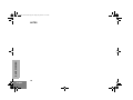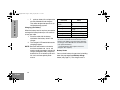
1
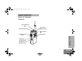
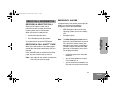
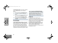
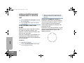
93C98-B_cvr.qxd
7/22/2005
10:32 AM
MOTOROLA and the Stylized M Logo are registered in the US Patent & Trademark Office.
All other product or service names are the property of their respective owners.
© Motorola, Inc. 2005. Inc. All rights reserved. Printed in U.S.A.
MOTOROLA, Le logo stylisé M,et intelligence universelle sont des marques de Motorola, Inc.
© 2005 Motorola, Inc. Tous droits réservés. Imprimé aux États-Unis.
Page 1
EX500™
Expert Series
Two-Way Radio User Guide
*6881093C98*
68P81093C98-B
Guide de l'utilisateur
de l'appareil radio émetteur-récepteur
04_RadioCall.fm Page 22 Friday, July 22, 2005 11:19 AM
00_EX500_NATOC.fm Page 1 Friday, July 22, 2005 10:33 AM
Computer Software Copyrights . . . . . . . 2
Safety . . . . . . . . . . . . . . . . . . . . . . . . . . . . 3
Radio Overview . . . . . . . . . . . . . . . . . . . . 5
Parts of the Radio . . . . . . . . . . . . . . . . . . . 5
On/Off/Volume Knob. . . . . . . . . . . . . . . 6
Channel Selector Knob . . . . . . . . . . . . . 6
Push-to-Talk (PTT) Button . . . . . . . . . . 6
Microphone . . . . . . . . . . . . . . . . . . . . . . 6
LED Indicator . . . . . . . . . . . . . . . . . . . . 6
Programmable Buttons . . . . . . . . . . . . . 6
Indicator Tones . . . . . . . . . . . . . . . . . . . . . 8
Audio Indicators for Programmable Buttons 8
Improved Audio Features. . . . . . . . . . . . . . 9
Low Level Expansion (LLE) . . . . . . . . . 9
Companding . . . . . . . . . . . . . . . . . . . . . 9
. . . . . . . . . . . . . . . . . . . . . . . . . . . . . . . . . 11
Battery Information. . . . . . . . . . . . . . . . . . 11
Battery Care and Tips . . . . . . . . . . . . . 11
Getting Started . . . . . . . . . . . . . . . . . . . . 11
Charging your Battery . . . . . . . . . . . . . 12
Battery Status . . . . . . . . . . . . . . . . . . . 12
Accessory Information . . . . . . . . . . . . . . . 14
Attaching the Battery . . . . . . . . . . . . . . 14
Removing the Battery . . . . . . . . . . . . . . 14
Attaching the Antenna . . . . . . . . . . . . . 15
Removing the Antenna . . . . . . . . . . . . .15
Attaching the Side Connector Cover . . 16
Turning The Radio On or Off . . . . . . . . . . . 16
Adjusting the Radio’s Volume . . . . . . . . . . 17
Selecting a Radio Channel . . . . . . . . . . . . 17
Sending a Call . . . . . . . . . . . . . . . . . . . . . . 17
Receiving a Call. . . . . . . . . . . . . . . . . . . . . 17
CONTENTS
CONTENTS
Radio Call information . . . . . . . . . . . . . . 19
Receiving a Selective Call . . . . . . . . . . . . .19
Receiving a Call Alert™ Page . . . . . . . . . . 19
Emergency Alarms . . . . . . . . . . . . . . . . . . 19
Talkaround. . . . . . . . . . . . . . . . . . . . . . . . . 20
Squelch . . . . . . . . . . . . . . . . . . . . . . . . . . . 20
Power Level. . . . . . . . . . . . . . . . . . . . . . . . 21
Scan . . . . . . . . . . . . . . . . . . . . . . . . . . . . . 23
Starting or Stopping a Scan Operation . . . 23
Talkback . . . . . . . . . . . . . . . . . . . . . . . . . . 23
Deleting a Nuisance Channel . . . . . . . . . . 23
Adding a Deleted Nuisance Channel back to
the Scan List . . . . . . . . . . . . . . . . . . . . . . . 24
Scan Channel Discovery Alert. . . . . . . . . . 24
Scan List Member Priority . . . . . . . . . . . . .24
1
English
00_EX500_NATOC.fm Page 2 Friday, July 22, 2005 10:33 AM
Warranty . . . . . . . . . . . . . . . . . . . . . . . . . 27
CONTENTS
Limited Warranty. . . . . . . . . . . . . . . . . . . . 27
Accessories . . . . . . . . . . . . . . . . . . . . . . 31
Carry Cases . . . . . . . . . . . . . . . . . . . . . . .
Remote Speaker MicrophoneS. . . . . . . . .
Earpieces . . . . . . . . . . . . . . . . . . . . . . . . .
Batteries . . . . . . . . . . . . . . . . . . . . . . . . . .
Chargers . . . . . . . . . . . . . . . . . . . . . . . . . .
Antennas . . . . . . . . . . . . . . . . . . . . . . . . .
31
31
31
31
31
32
COMPUTER SOFTWARE
COPYRIGHTS
The Motorola products described in this
manual may include copyrighted Motorola
computer programs stored in
semiconductor memories or other media.
Laws in the United States and other
countries preserve for Motorola certain
exclusive rights for copyrighted computer
programs, including, but not limited to, the
exclusive right to copy or reproduce in any
form the copyrighted computer program.
Accordingly, any copyrighted Motorola
computer programs contained in the
Motorola products described in this manual
2
English
may not be copied, reproduced, modified,
reverse-engineered, or distributed in any
manner without the express written
permission of Motorola. Furthermore, the
purchase of Motorola products shall not be
deemed to grant either directly or by
implication, estoppel, or otherwise, any
license under the copyrights, patents or
patent applications of Motorola, except for
the normal non-exclusive license to use that
arises by operation of law in the sale of a
product.
01_Safety.fm Page 3 Friday, July 22, 2005 10:33 AM
SAFETY
S
PRODUCT SAFETY AND RF
EXPOSURE COMPLIANCE
!
Caution
Before using this product, read the
operating instructions for safe usage
contained in the Product Safety and
RF Exposure booklet enclosed with
your radio.
SAFETY
ATTENTION!
This radio is restricted to occupational use
only to satisfy FCC RF energy exposure
requirements. Before using this product, read
the RF energy awareness information and
operating instructions in the Product Safety
and RF Exposure booklet enclosed with your
radio (Motorola Publication part number
68P81095C98) to ensure compliance with RF
energy exposure limits.
For a list of Motorola-approved antennas,
batteries, and other accessories, visit the
following web site which lists approved
accessories: http://www.motorola.com/cgiss/
index.shtml.
3
English
01_Safety.fm Page 4 Friday, July 22, 2005 10:33 AM
SAFETY
NOTES
4
English
02_Radio Overview.fm Page 5 Friday, July 22, 2005 11:12 AM
RADIO OVERVIEW
PARTS OF THE RADIO
EX500 Model
Channel Selector
Knob
On/Off/Volume Knob
Top Button
(programmable)
LED Indicator
Push-to-Talk (PTT)
Button
Microphone
RADIO OVERVIEW
Side Button 1
(programmable)
Side Button 2
(programmable)
5
English
02_Radio Overview.fm Page 6 Friday, July 22, 2005 11:12 AM
On/Off/Volume Knob
Programmable Buttons
Turns the radio on or off, and adjusts the
radio’s volume.
Several of the radio’s buttons can be
programmed as short-cut buttons for many of
the radio’s features. Programmable buttons
include:
• Top button,
• two side buttons
Each button can access up to two features,
depending on the type of button press:
Channel Selector Knob
Switches the radio to different channels.
Push-to-Talk (PTT) Button
Press and hold down this button to talk,
release it to listen.
Microphone
Speak clearly into the microphone when
sending a message.
LED Indicator
RADIO OVERVIEW
Gives battery status, power-up status, radio
call information and scan status.
6
English
•
short press - quickly pressing and
releasing the programmable buttons,
or
• long press - pressing and holding the
programmable buttons for at least
1 1/2 seconds, or
• hold down - pressing and holding
down the programmable buttons while
checking status or making adjustments.
The table on page 17 summarizes the
programmable features available.
02_Radio Overview.fm Page 7 Friday, July 22, 2005 11:12 AM
Button
Short Press
Long Press
Press and Hold
Page
Initiates an Emergency Alert.
Cancels your radio’s
Emergency status.
—
29
Monitor/Permanent Monitor
—
Continually monitors the
selected channel.
Monitors the selected
channel for any activity.
33
Volume Set
—
—
Sounds a tone for
adjusting the radio’s volume level.
27
Battery Gauge
—
—
Checks the battery’s
charge status.
22
Scan/Nuisance
Channel Delete
Toggles Scan on and
off.
Deletes a nuisance
channel while scanning.
—
33
Tx Power
Toggles your radio’s transmit power level
between High and Low power.†
—
31
Repeater/
Talkaround
Toggle between using a repeater or transmitting
directly to another radio.†
—
30
Squelch
Toggles your radio’s squelch level between tight/
normal squelch.†
—
30
RADIO OVERVIEW
Emergency*
Button
*
If Emergency function is required, it can ONLY be programmed to the Top Button.
Depending on how your radio has been programmed by your dealer, these functions are activated EITHER through
short press OR long press, but not both.
†
7
English
02_Radio Overview.fm Page 8 Friday, July 22, 2005 11:12 AM
INDICATOR TONES
High pitched tone
Low pitched tone
Self Test Pass Tone
RADIO OVERVIEW
Self Test Fail Tone
8
English
AUDIO INDICATORS FOR
PROGRAMMABLE BUTTONS
Some programmable keys function as toggles
(alternating between two different choices).
These keys use audio indicators to indicate the
change.
Positive
Indicator
Tone
Negative
Indicator
Tone
Scan
Starts Scan
operation
Stops Scan
operation
Tx Power
Transmits at
low power
Transmits at
high power
Squelch
Operates in
tight squelch
Operates in
normal
squelch
Repeater/
Talkaround
DOES NOT
use the
repeater
Uses the
repeater
Positive Indicator Tone
Programmable
Buttons
Negative Indicator Tone
02_Radio Overview.fm Page 9 Friday, July 22, 2005 11:12 AM
IMPROVED AUDIO FEATURES
Low Level Expansion (LLE)
The LLE feature of your radio improves voice
quality by reducing unwanted background
noise when receiving a message. It is
compatible with most major types of audio
processing systems available today.
Companding
Companding is a feature that allows further
improvement of voice quality. It compresses
your voice at transmission, and expands it
when receiving while simultaneously reducing
extraneous noise. However, to enjoy this
benefit, ALL transmitting and receiving radios
must have this feature activated.
RADIO OVERVIEW
NOTE: Contact your dealer for your radio’s
current companding settings or to
change the settings.
9
English
02_Radio Overview.fm Page 10 Friday, July 22, 2005 11:12 AM
RADIO OVERVIEW
NOTES
10
English
03_GettingStarted.fm Page 11 Friday, July 22, 2005 11:12 AM
]
BATTERY INFORMATION
•
Charging a hot battery (above 95°F
[35°C]) results in reduced discharge
capacity, affecting the performance of
the radio. Motorola rapid-rate battery
chargers contain a temperaturesensing circuit to ensure that the
battery is charged within these
temperature limits.
•
New batteries can be stored up to two
years without significant cycle loss.
Store new/unused batteries in a cool
dry area.
•
Batteries which have been in storage
should be charged overnight.
•
Do not return fully charged batteries to
the charger for an “extra boost”. This
action will significantly reduce cycle
life.
•
Do not leave your radio and battery in
the charger when not charging.
Continuous charging will shorten
battery life. (Do not use your charger
as a radio stand.)
Battery Care and Tips
This product is powered by a rechargeable
battery.
The following battery tips will help you obtain
the highest performance and longest cycle life
from your Motorola rechargeable battery.
•
Batteries are shipped uncharged from
the factory. Always charge a new
battery 14 - 16 hours before initial use,
regardless of the status indicated by
the charger.
•
Charging in non-Motorola equipment
may lead to battery damage and void
the battery warranty.
•
When charging a battery that is
attached to the radio, turn the radio off
to ensure a full charge.
•
The battery should be at about 77°F
(25°C) (room temperature) whenever
possible. Charging a cold battery,
(below 50°F [10°C]) may result in
GETTING STARTED
leakage of electrolyte and ultimately, in
failure of the battery.
GETTING STARTED
11
English
03_GettingStarted.fm Page 12 Friday, July 22, 2005 11:12 AM
GETTING STARTED
•
For optimum battery life and operation
use only Motorola brand chargers.
They were designed to operate as an
integrated energy system.
Charging your Battery
When the battery level is very low, you need to
recharge the battery before you can continue
to use your radio.
1. Place the radio with the battery
attached or the battery alone in the
charger.
2. The charger’s LED would indicate the
charging progress.
NOTE: Because new batteries or batteries
that have not been used for several
months could prematurely indicate full
charge (solid green LED), charge the
batteries for 14 to 16 hours prior to initial use to achieve optimal performance.
12
English
LED color
Status
Single flash of
Green
Flashing Red*
Flashing Yellow
Successful charger powerup.
Battery is unchargeable.
Charger is getting ready to
charge.
Red
Battery is charging.
Flashing Green†
Battery is 90% charged.
Green
Battery is fully charged.
* Remove the battery from charger and use a pencil eraser to clean the four metal contacts on the
bottom of the battery. Place the battery back into
the charger. If the LED indicator continues to flash
red, replace the battery.
† A standard battery may require one hour to
charge to 90% capacity.
Battery Status
You can check battery charge status by holding
down the preprogrammed Battery Gauge
button (see page 17). The charge status is
03_GettingStarted.fm Page 13 Friday, July 22, 2005 11:12 AM
Battery
Level
High
Satisfactory
Low
Very Low
GETTING STARTED
shown is shown by the color of the radio’s LED
Indicator.
LED Indicator
Green
Yellow
Flashing Red
None
NOTE: If the Battery Gauge indicator does
NOT appear, this indicates that the
battery may not be a genuine Motorola
product.
13
English
GETTING STARTED
03_GettingStarted.fm Page 14 Friday, July 22, 2005 11:12 AM
ACCESSORY INFORMATION
Attaching the Battery
Battery
Latches
1
Fit the extensions at the bottom of the battery
into the slots at the bottom of the radio.
2
Press the top part of the battery towards the
radio until a click is heard.
Note:
14
English
Removing the Battery
It is important to make sure that both
battery latches are secured.
1
Turn off the radio, if it is turned on.
2
Slide the battery latches, on both sides of the
battery, downwards.
3
Pull the top part of the battery away from the
radio.
03_GettingStarted.fm Page 15 Friday, July 22, 2005 11:12 AM
1
Align the threaded end of the antenna with the
radio’s antenna connector.
2
Turn the antenna clockwise to attach it.
Removing the Antenna
GETTING STARTED
Attaching the Antenna
Turn the antenna counterclockwise to remove it.
15
English
GETTING STARTED
03_GettingStarted.fm Page 16 Friday, July 22, 2005 11:12 AM
Attaching the Side Connector Cover
TURNING THE RADIO ON OR OFF
Antenna
Loop
Slot
Thumbscrew
1
Place the loop (attached to the side connector
cover) over the antenna; then slide it downward until it touches the top of the radio.
2
Insert the tab on the top of the cover into the
slot above the connector.
3
Position the cover over the connector and
align the thumbscrew with the threaded hole
in the radio.
4
Tighten the thumbscrew to hold the cover in
place. Do not overtighten the thumbscrew.
ON
1
2
16
English
OFF
Turn the On/Off/Volume (see page 15) knob
clockwise to turn on the radio. You will hear
the Self Test Pass Tone and see a green
LED if the radio powers up successfully. If
the radio fails to power up, you will hear the
Self Test Fail Tone.
Turn the On/Off/Volume knob (see page 15)
counter-clockwise, until a click is heard, to
turn off the radio.
03_GettingStarted.fm Page 17 Friday, July 22, 2005 11:12 AM
SENDING A CALL
1
Press and hold the Volume Set button (see
page 17); you will hear a continuous tone.
1
2
2
Turn the On/Off/Volume knob (see page 16)
and adjust the volume level.
3
3
Release the Volume Set button (see
page 17).
SELECTING A RADIO CHANNEL
Your radio offers sixteen (16) channels for easy
access to required conventional channels.
Some channels on your radio may not be
programmed. Check with your dealer for more
information.
To select a channel:
4
Turn your radio on.
Use the Channel Selector knob (see
page 15) to select to the desired channel.
Press the PTT button (see page 15), and
speak clearly with your mouth about 2.5 to 5
cm (one to two inches) away from the microphone.
Release the PTT button (see page 15) when
you finish speaking.
GETTING STARTED
ADJUSTING THE RADIO’S VOLUME
RECEIVING A CALL
1
2
3
4
Turn your radio on.
Adjust the radio’s volume.
Switch to the desired channel.
If at any time a call comes through, you will
hear the call at the volume level you have
set.
Turn the Channel Selector knob (see page 15)
clockwise or counter-clockwise until you reach the
desired channel.
17
English
GETTING STARTED
03_GettingStarted.fm Page 18 Friday, July 22, 2005 11:12 AM
NOTES
18
English
04_RadioCall.fm Page 19 Friday, July 22, 2005 11:13 AM
RADIO CALL INFORMATION
RECEIVING A SELECTIVE CALL
Selective Call allows a radio user to
communicate with a single unit without
involving other units in conversation.
EMERGENCY ALARMS
If programmed by your dealer, the orange Top
button can send one of the following
emergency alarms described below:
•
MDC Emergency Alarm (only if the
signaling system you are on is MDC),
and
•
Emergency Siren
When you receive a selective call:
•
You will hear two alert tones.
•
The LED Indicator will light yellow.
Press the PTT button to answer the Call Alert
page, or press any other key to cancel it.
•
continually give visual and audio
feedback,
Note: Your radio will not receive any Selective
Calls until you clear the page.
•
give no audio feedback, but with
visual feedback, or
•
give no audio/visual feedback, but
the radio can receive and transmit.
RECEIVING A CALL ALERT™ PAGE
Note:
RADIO CALL
INFORMATION
When your radio receives a Call Alert page, it
sounds four alert tones continuously until you
respond.
The MDC Emergency Alarm feature
gives you a one-button quick access to
call a particular radio or center (predefined by your dealer) in emergency
situations. When activated, the radio
goes into an Emergency state, which
can be programmed to
To answer the call, press the PTT button.
19
English
04_RadioCall.fm Page 20 Friday, July 22, 2005 11:13 AM
RADIO CALL
INFORMATION
The Emergency Siren will cause the radio to
sound a repetitive tone at the maximum
volume.
1
Press and release the Emergency button
(see page 17) to initiate an Emergency
Alarm.
2
Press and hold the Emergency button (see
page 17) to cancel the Emergency Alarm.
3
Press and release the Emergency button
(see page 17) to restart the Emergency
sequence.
TALKAROUND
In your communications network, you may be
using a repeater to cover a larger area than
what is possible with your radio. However, you
can communicate with another radio within
your radio’s range without going through the
repeater by using the Talkaround feature. This
is especially useful when the repeater is down
20
English
Press the programmed Repeater/Talkaround
button to toggle between the options of making or
not making a call through the repeater. A positive
indicator tone indicates that the radio is in
talkaround mode, while a negative indicator tone
indicates that the radio is in repeater mode.
SQUELCH
If a particular channel receives many
unwanted calls coming from radios that do not
belong to your communications group and are
some distance away, or the “background noise”
is excessive, you can try to filter these
transmissions out by tightening the channel’s
squelch. However, tightening squelch could
cause calls from members of your
communications group that are farther away to
be filtered out as well.
04_RadioCall.fm Page 21 Friday, July 22, 2005 11:13 AM
To set the squelch level:
Press the programmed Squelch button to toggle
between the options of having normal squelch or
tightening the squelch of your radio. A positive
indicator tone indicates that the radio is operating
in tight squelch, while a negative indicator tone
indicates that the radio is operating in normal
squelch.
POWER LEVEL
RADIO CALL
INFORMATION
You can transmit your calls at different transmit
power levels. A higher level means you can
reach a radio that is farther away. Lower power
level conserves battery power. You are advised
to transmit as frequently as possible on low
power, and use high power only when needed.
Press the programmed Tx Power button to toggle
between the options for High or Low power transmit level. A positive indicator tone indicates that
the radio is operating in low power mode, while a
negative indicator tone indicates that the radio is
operating in high power mode.
21
English
04_RadioCall.fm Page 22 Friday, July 22, 2005 11:13 AM
RADIO CALL
INFORMATION
NOTES
22
English
05_Scan.fm Page 23 Friday, July 22, 2005 11:13 AM
SCAN
You can monitor several channels in order to
receive any call that is transmitted on any of
these channels. Sixteen different channels can
be programmed into a scan list. Each channel
can share the same scan list or have different
scan lists assigned to them.
Once the radio’s scan operation is activated
and the radio detects a call coming through a
channel in its scan list, it switches to that
channel for you to receive the call.
TALKBACK
If the programmable Talkback option is set, you
can respond to any calls received during the
scan operation by pressing the PTT button
before the programmed hang-time ends.
Check with your dealer for details.
DELETING A NUISANCE CHANNEL
If a channel continually generates unwanted
calls/noise, you can temporarily remove it from
the scan list by performing a Nuisance
Channel Delete operation.
STARTING OR STOPPING A SCAN
OPERATION
1
The LED Indicator will blink (green) during a
scan operation. It will stop blinking when the
radio switches to a channel.
2
1
Note:
You cannot perform a Nuisance Channel Delete on a priority channel or if
there is only one remaining channel in
the scan list.
SCAN
2
Press the Scan button (see page 17) to start
a scan operation.
Press the Scan button again to stop the scan
operation.
While the radio is on the Nuisance Channel,
press and hold the Scan button (see page
17) until you hear a tone.
Release the Scan button.
23
English
05_Scan.fm Page 24 Friday, July 22, 2005 11:13 AM
ADDING A DELETED NUISANCE
CHANNEL BACK TO THE SCAN
LIST
3
When you reach the last channel the scan
operation switched to, the radio sounds an
alert tone.
SCAN LIST MEMBER PRIORITY
SCAN CHANNEL DISCOVERY
ALERT
SCAN
Ch.4
1
Stop the scan operation.
2
Turn the Channel Selector knob (see page
15) to change the channels.
24
English
Ch.1
Ch.
3
To do this:
Assuming a scan list with 6 channels, if all your
channels are non-prioritized, the normal scan
operation would check for activity in the
following sequence:
.2
Ch
Sometimes you need to know which channel
the radio has switched to during a scan
operation. The Scan Channel Discovery Alert
gives you this information.
After you have stopped a scan operation, this
feature gives you audio feedback when you
select the last channel that was switched to by
the scan operation.
A channel in your scan list may be prioritized
(check with your dealer for details). In such a
case, the radio will check that prioritized
channel more frequently than the other nonprioritized channels.
Ch.
6
2
Press the Scan button (see page 17) to stop
the scan operation.
Press the Scan button again to re-start the
scan operation.
.5
Ch
1
05_Scan.fm Page 25 Friday, July 22, 2005 11:13 AM
If Channel 2 is prioritized, the scan operation
would change to
Ch.2
Ch
.1
Ch.2
2
Ch.
5
Ch.
.6
Ch
Ch.3
2
.2
Ch
Ch
.
Ch.4
Note:
Even though your radio has switched
to a non-priority channel, your radio
will still check for activity on the priority
channel. If some activity is detected
there, the radio will switch to that priority channel.
SCAN
25
English
05_Scan.fm Page 26 Friday, July 22, 2005 11:13 AM
SCAN
NOTES
26
English
06_Warranty.fm Page 27 Friday, July 22, 2005 11:14 AM
WARRANTY
I. WHAT THIS WARRANTY COVERS AND
FOR HOW LONG:
MOTOROLA INC. (“MOTOROLA”) warrants the
MOTOROLA manufactured Communication
Products listed below (“Product”) against defects
in material and workmanship under normal use
and service for a period of time from the date of
purchase as scheduled below:
EX500 Units
Three (3) Years
Product Accessories
One (1) Year
Motorola, at its option, will at no charge either
repair the Product (with new or reconditioned
parts), replace it (with a new or reconditioned
Product), or refund the purchase price of the
Product during the warranty period provided it is
returned in accordance with the terms of this
warranty. Replaced parts or boards are warranted
WARRANTY
LIMITED WARRANTY
MOTOROLA COMMUNICATION
PRODUCTS
for the balance of the original applicable warranty
period. All replaced parts of Product shall become
the property of MOTOROLA.
This express limited warranty is extended by
MOTOROLA to the original end user purchaser
only and is not assignable or transferable to any
other party. This is the complete warranty for the
Product manufactured by MOTOROLA.
MOTOROLA assumes no obligations or liability
for additions or modifications to this warranty
unless made in writing and signed by an officer
of MOTOROLA. Unless made in a separate
agreement between MOTOROLA and the
original end user purchaser, MOTOROLA does
not warrant the installation, maintenance or
service of the Product.
MOTOROLA cannot be responsible in any way
for any ancillary equipment not furnished by
MOTOROLA which is attached to or used in
connection with the Product, or for operation of
the Product with any ancillary equipment, and all
such equipment is expressly excluded from this
warranty. Because each system which may use
the Product is unique, MOTOROLA disclaims
liability for range, coverage, or operation of the
system as a whole under this warranty.
27
English
06_Warranty.fm Page 28 Friday, July 22, 2005 11:14 AM
II. GENERAL PROVISIONS:
WARRANTY
This warranty sets forth the full extent of
MOTOROLA'S responsibilities regarding the
Product. Repair, replacement or refund of the
purchase price, at MOTOROLA’s option, is the
exclusive remedy. THIS WARRANTY IS GIVEN
IN LIEU OF ALL OTHER EXPRESS
WARRANTIES. IMPLIED WARRANTIES,
INCLUDING WITHOUT LIMITATION, IMPLIED
WARRANTIES OF MERCHANTABILITY AND
FITNESS FOR A PARTICULAR PURPOSE, ARE
LIMITED TO THE DURATION OF THIS LIMITED
WARRANTY. IN NO EVENT SHALL MOTOROLA
BE LIABLE FOR DAMAGES IN EXCESS OF
THE PURCHASE PRICE OF THE PRODUCT,
FOR ANY LOSS OF USE, LOSS OF TIME,
INCONVENIENCE, COMMERCIAL LOSS, LOST
PROFITS OR SAVINGS OR OTHER
INCIDENTAL, SPECIAL OR CONSEQUENTIAL
DAMAGES ARISING OUT OF THE USE OR
INABILITY TO USE SUCH PRODUCT, TO THE
FULL EXTENT SUCH MAY BE DISCLAIMED BY
LAW.
III. STATE LAW RIGHTS:
SOME STATES DO NOT ALLOW THE
EXCLUSION OR LIMITATION OF INCIDENTAL
28
English
OR CONSEQUENTIAL DAMAGES OR
LIMITATION ON HOW LONG AN IMPLIED
WARRANTY LASTS, SO THE ABOVE
LIMITATION OR EXCLUSIONS MAY NOT
APPLY.
This warranty gives specific legal rights, and there
may be other rights which may vary from state to
state.
IV. HOW TO GET WARRANTY SERVICE:
You must provide proof of purchase (bearing the
date of purchase and Product item serial
number) in order to receive warranty service and,
also, deliver or send the Product item,
transportation and insurance prepaid, to an
authorized warranty service location. Warranty
service will be provided by Motorola through one
of its authorized warranty service locations. If you
first contact the company which sold you the
Product (e.g., dealer or communication service
provider), it can facilitate your obtaining warranty
service. You can also call Motorola at 1-800-9272744 US/Canada.
06_Warranty.fm Page 29 Friday, July 22, 2005 11:14 AM
V. WHAT THIS WARRANTY DOES NOT
COVER:
B)
C)
D)
E)
F)
G)
Defects or damage resulting from use of the
Product in other than its normal and
customary manner.
Defects or damage from misuse, accident,
water, or neglect.
Defects or damage from improper testing,
operation, maintenance, installation,
alteration, modification, or adjustment.
Breakage or damage to antennas unless
caused directly by defects in material
workmanship.
A Product subjected to unauthorized
Product modifications, disassemblies or
repairs (including, without limitation, the
addition to the Product of non-Motorola
supplied equipment) which adversely affect
performance of the Product or interfere with
Motorola's normal warranty inspection and
testing of the Product to verify any warranty
claim.
Product which has had the serial number
removed or made illegible.
Rechargeable batteries if:
1) any of the seals on the battery
enclosure of cells are broken or show
evidence of tampering.
the damage or defect is caused by
charging or using the battery in
equipment or service other than the
Product for which it is specified.
H) Freight costs to the repair depot.
I) A Product which, due to illegal or
unauthorized alteration of the software/
firmware in the Product, does not function in
accordance with MOTOROLA’s published
specifications or the FCC type acceptance
labeling in effect for the Product at the time
the Product was initially distributed from
MOTOROLA.
J) Scratches or other cosmetic damage to
Product surfaces that does not affect the
operation of the Product.
K) Normal and customary wear and tear.
WARRANTY
A)
2)
VI. PATENT AND SOFTWARE PROVISIONS:
MOTOROLA will defend, at its own expense, any
suit brought against the end user purchaser to
the extent that it is based on a claim that the
Product or parts infringe a United States patent,
and MOTOROLA will pay those costs and
damages finally awarded against the end user
purchaser in any such suit which are attributable
to any such claim, but such defense and
payments are conditioned on the following:
29
English
06_Warranty.fm Page 30 Friday, July 22, 2005 11:14 AM
WARRANTY
A) that MOTOROLA will be notified promptly in
writing by such purchaser of any notice of
such claim;
B) that MOTOROLA will have sole control of the
defense of such suit and all negotiations for
its settlement or compromise; and
C) should the Product or parts become, or in
MOTOROLA’s opinion be likely to become,
the subject of a claim of infringement of a
United States patent, that such purchaser
will permit MOTOROLA, at its option and
expense, either to procure for such
purchaser the right to continue using the
Product or parts or to replace or modify the
same so that it becomes non-infringing or to
grant such purchaser a credit for the Product
or parts as depreciated and accept its
return. The depreciation will be an equal
amount per year over the lifetime of the
Product or parts as established by
MOTOROLA.
MOTOROLA will have no liability with respect to
any claim of patent infringement which is based
upon the combination of the Product or parts
furnished hereunder with software, apparatus or
devices not furnished by MOTOROLA, nor will
MOTOROLA have any liability for the use of
ancillary equipment or software not furnished by
MOTOROLA which is attached to or used in
30
English
connection with the Product. The foregoing
states the entire liability of MOTOROLA with
respect to infringement of patents by the Product
or any parts thereof.
Laws in the United States and other countries
preserve for MOTOROLA certain exclusive rights
for copyrighted MOTOROLA software such as
the exclusive rights to reproduce in copies and
distribute copies of such Motorola software.
MOTOROLA software may be used in only the
Product in which the software was originally
embodied and such software in such Product
may not be replaced, copied, distributed,
modified in any way, or used to produce any
derivative thereof. No other use including, without
limitation, alteration, modification, reproduction,
distribution, or reverse engineering of such
MOTOROLA software or exercise of rights in
such MOTOROLA software is permitted. No
license is granted by implication, estoppel or
otherwise under MOTOROLA patent rights or
copyrights.
VII. GOVERNING LAW:
This Warranty is governed by the laws of the
State of Illinois, USA.
07_Accessories.fm Page 31 Friday, July 22, 2005 11:14 AM
ACCESSORIES
BATTERIES
JMNN4023 1000 mAH Li-Ion High Capacity Battery
Motorola offers a number of accessories to
enhance the productivity of your two-way radio.
Many of the available accessories are listed
below. Your authorized Motorola dealer will
also have a complete list of accessories.
Additional Accessories will be available for this
product in the near future.
HLN9985
Waterproof Bag
JMZN4020
Radio Handstrap
JMZN4023
Plastic Carry Holder with Swivel Belt Clip
CHARGERS
AAHTN3000
120V Single-Unit Rapid Charger, US Plug
AAHTN3003
120V Multi-Unit Rapid Charger, US Plug
Note: You must use the “C” version multi-charger or
newer to be compatible with the EX500.
ACCESSORIES
CARRY CASES
JMNN4024 1320 mAH Li-Ion Ultra High Capacity
Battery
PMLN4421 Soft Leather Case with Fixed Swivel Clip
REMOTE SPEAKER MICROPHONES
JMMN4073 Remote Speaker Microphone
EARPIECES
JMMN4062
2 Wire Surveillance Earpiece
31
English
07_Accessories.fm Page 32 Friday, July 22, 2005 11:14 AM
ANTENNAS
PMAD4012 VHF 136-155 MHz 9cm, Stubby
PMAD4013 VHF 155-174 MHz 9cm, Stubby
PMAD4014 VHF 136-155 MHz 14cm, Standard
PMAD4015 VHF 155-174 MHz 14cm, Standard
PMAD4023 VHF 150-161 MHz, 14cm
PMAD4025 VHF 150-161 MHz, 9cm
PMAE4002 403-433 MHz Stubby Antenna
ACCESSORIES
PMAE4003 433-470 MHz Stubby Antenna
NAE6483
PMAE4007 UHF 490-512 MHz, 9cm
PMAE4008 UHF 470-512 MHz, Whip
32
English
403-512 MHz Whip Antenna
PMAE4006 UHF 470-510 MHz, 9cm, Helical
08_QuickRef.fm Page 33 Friday, July 22, 2005 11:28 AM
Adding a Deleted Nuisance Channel back to
the Scan List
1.
2.
EX500 Quick Reference Card
Press the preprogrammed Scan button to stop the scan
operation.
Press the preprogrammed Scan button again to re-start the
scan operation.
Channel Selector Knob
Programmable
Buttons
Positive
Indicator Tone
Negative
Indicator Tone
Scan
Starts Scan
operation
Stops Scan
operation
Tx Power
Transmits at low
power
Transmits at high
power
Squelch
Operates in tight
squelch
Operates in
normal squelch
Radio DOES
NOT use the
repeater
Radio uses the
repeater
Repeater/
Talkaround
Top Button
(programmable)
On/Off/Volume Knob
Programmable Buttons’ Audio Indicators
LED Indicator
Push-to-Talk
(PTT) Button
Microphone
Side Button 1
(programmable)
Side Button 2
(programmable)
Button
Function
Short Press
Long Press
Hold Down
Page
08_QuickRef.fm Page 34 Friday, July 22, 2005 11:28 AM
Turning On the Radio
Receiving a Call
•
1.
2.
3.
4.
Turn On/Off/Volume knob clockwise. Self Test Pass Tone
will sound and green LED will light up if radio powers up
successfully. If radio fails power up, the Self Test Fail Tone
will sound.
Turning Off the Radio
•
Turn On/Off/Volume knob counter-clockwise, until click is
heard.
Emergency Alarm
1.
Adjusting the Radio’s Volume
2.
1.
3.
2.
3.
Press and hold Volume Set button until continuous tone is
sounded.
Turn On/Off/Volume knob to adjust volume level.
Release Volume Set button when desired level is achieved.
Selecting a Radio Channel
•
Turn Channel Selector knob clockwise or counter-clockwise to reach desired channel.
Sending a Call
1.
2.
3.
4.
Turn on radio.
Use Channel Selector knob to select the desired channel.
Press PTT button, and speak clearly with mouth about 2.5
to 5 cm (one to two inches) away from microphone.
Release PTT button when call is completed.
Turn radio on.
Adjust volume level.
Switch to desired channel.
If at any time a call comes through, it will be heard at the
volume level set.
Press programmed Emergency button to initiate Emergency Alarm/Siren.
Press and hold Emergency button to cancel Emergency
Alarm/Siren.
Press and release Emergency button to restart Emergency
sequence.
Starting or Stopping a Scan Operation
The LED Indicator will blink (green) during a scan operation. It
will stop blinking when the radio switches to a channel.
1. Press the preprogrammed Scan button to start a scan operation.
2. Press the preprogrammed Scan button again to stop the
scan operation.
Deleting a Nuisance Channel
1.
2.
While radio is on a Nuisance Channel, press and hold the
preprogrammed Scan button until a tone is sounded.
Release the preprogrammed Scan button.
04_RadioCall.fm Page 22 Friday, July 22, 2005 11:19 AM
93C98-B_cvr.qxd
7/22/2005
10:32 AM
MOTOROLA and the Stylized M Logo are registered in the US Patent & Trademark Office.
All other product or service names are the property of their respective owners.
© Motorola, Inc. 2005. Inc. All rights reserved. Printed in U.S.A.
MOTOROLA, Le logo stylisé M,et intelligence universelle sont des marques de Motorola, Inc.
© 2005 Motorola, Inc. Tous droits réservés. Imprimé aux États-Unis.
Page 1
EX500™
Expert Series
Two-Way Radio User Guide
*6881093C98*
68P81093C98-B
Guide de l'utilisateur
de l'appareil radio émetteur-récepteur