1
Ignite
LIVE PRODUCTION CONTROL SYSTEM
SDC/HDC Robotic Camera
Instruction Manual
071849200
SEPTEMBER 2006
Affiliate with the N.V. KEMA in The Netherlands
CERTIFICATE
Certificate Number: 510040.001
The Quality System of:
Grass Valley, Inc.
400 Providence Mine Road
Nevada City, CA 95945
United States
15655 SW Greystone Ct.
Beaverton, OR 97006
United States
10 Presidential Way
rd
3 Floor, Suite 300
Woburn, MA 01801
United States
Nederland B.V.
4800 RP BREDA
The Netherlands
Weiterstadt, Germany
Brunnenweg 9
D-64331 Weiterstadt
Germany
Rennes, France
Rue du Clos Courtel
Cesson-Sevigne, Cedex
France
Technopole Brest Iroise
CS 73808
29238 Brest Cedex 3
France
17 rue du Petit Albi-BP 8244
95801 Cergy Pontoise
Cergy, France
2300 South Decker Lake Blvd.
Salt Lake City, UT 84119
United States
7140 Baymeadows Way
Suite 101
Jacksonville, FL 32256
United States
Including its implementation, meets the requirements of the standard:
ISO 9001:2000
Scope:
The design, manufacture and support of video hardware and software products and
related systems.
This Certificate is valid until:
This Certificate is valid as of:
Certified for the first time:
June 14, 2009
August 30, 2006
June 14, 2000
H. Pierre Sallé
President
KEMA-Registered Quality
The method of operation for quality certification is defined in the KEMA General Terms
And Conditions For Quality And Environmental Management Systems Certifications.
Integral publication of this certificate is allowed.
KEMA-Registered Quality, Inc.
4377 County Line Road
Chalfont, PA 18914
Ph: (215)997-4519
Fax: (215)997-3809
CRT 001 073004
Accredited By:
ANAB
Ignite
LIVE PRODUCTION CONTROL SYSTEM
SDC/HDC Robotic Camera
Instruction Manual
071849200
SEPTEMBER 2006
Contacting Grass Valley
Region
Voice
Fax
Address
Web Site
North America
(800) 547-8949
Support: 530-478-4148
Sales: (530) 478-3347
Support: (530) 478-3181
www.thomsongrassvalley.com
Pacific Operations
+852-2585-6688
Support: 852-2585-6579
+852-2802-2996
Grass Valley
P.O. Box 599000
Nevada City, CA 95959-7900
USA
U.K., Asia, Middle East
+44 1753 218 777
+44 1753 218 757
France
+33 1 45 29 73 00
Germany, Europe
+49 6150 104 782
+49 6150 104 223
Copyright © Grass Valley. All rights reserved.
This product may be covered by one or more U.S. and foreign patents.
Grass Valley Web Site
The www.thomsongrassvalley.com web site offers the following:
Online User Documentation — Current versions of product catalogs, brochures,
data sheets, ordering guides, planning guides, manuals, and release notes
in .pdf format can be downloaded.
FAQ Database — Solutions to problems and troubleshooting efforts can be
found by searching our Frequently Asked Questions (FAQ) database.
Software Downloads — Software updates, drivers, and patches can be down-
loaded.
4
Ignite SDC/HDC Robotic Camera Instruction Manual
Contents
Contents
Preface. . . . . . . . . . . . . . . . . . . . . . . . . . . . . . . . . . . . . . . . . . . . . . . . . . . . . . . . . . . . . . . . . . . . .
9
About This Manual . . . . . . . . . . . . . . . . . . . . . . . . . . . . . . . . . . . . . . . . . . . . . . . . . . . . . 9
Standard Documentation . . . . . . . . . . . . . . . . . . . . . . . . . . . . . . . . . . . . . . . . . . . . . . . . 9
Other Documentation. . . . . . . . . . . . . . . . . . . . . . . . . . . . . . . . . . . . . . . . . . . . . . . . . . . 9
Safety Summary
Safety Terms and Symbols. . . . . . . . . . . . . . . . . . . . . . . . . . . . . . . . . . . . . . . . . . . . . .
Terms in This Manual . . . . . . . . . . . . . . . . . . . . . . . . . . . . . . . . . . . . . . . . . . . . . . . .
Terms on the Product . . . . . . . . . . . . . . . . . . . . . . . . . . . . . . . . . . . . . . . . . . . . . . . .
Symbols on the Product . . . . . . . . . . . . . . . . . . . . . . . . . . . . . . . . . . . . . . . . . . . . . .
Warnings . . . . . . . . . . . . . . . . . . . . . . . . . . . . . . . . . . . . . . . . . . . . . . . . . . . . . . . . . . . .
Cautions . . . . . . . . . . . . . . . . . . . . . . . . . . . . . . . . . . . . . . . . . . . . . . . . . . . . . . . . . . . . .
11
11
11
12
12
13
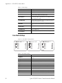
Regulatory Notices
Certifications and Compliances . . . . . . . . . . . . . . . . . . . . . . . . . . . . . . . . . . . . . . . . .
FCC Emission Control . . . . . . . . . . . . . . . . . . . . . . . . . . . . . . . . . . . . . . . . . . . . . . .
Canadian EMC Notice of Compliance . . . . . . . . . . . . . . . . . . . . . . . . . . . . . . . . . .
EN55022 Class A Warning . . . . . . . . . . . . . . . . . . . . . . . . . . . . . . . . . . . . . . . . . . . .
Canadian Certified Power Cords . . . . . . . . . . . . . . . . . . . . . . . . . . . . . . . . . . . . . .
Canadian Certified AC Adapter . . . . . . . . . . . . . . . . . . . . . . . . . . . . . . . . . . . . . . .
Certification . . . . . . . . . . . . . . . . . . . . . . . . . . . . . . . . . . . . . . . . . . . . . . . . . . . . . . . .
15
15
15
15
16
16
16
Section 1 — Overview . . . . . . . . . . . . . . . . . . . . . . . . . . . . . . . . . . . . . . . . . . . . . . . . . . .
17
Introduction . . . . . . . . . . . . . . . . . . . . . . . . . . . . . . . . . . . . . . . . . . . . . . . . . . . . . . . . . .
Hardware Description . . . . . . . . . . . . . . . . . . . . . . . . . . . . . . . . . . . . . . . . . . . . . . . . .
Additional Equipment (Required) . . . . . . . . . . . . . . . . . . . . . . . . . . . . . . . . . . . . . . .
SHOT Director Robotics/Camera Controller . . . . . . . . . . . . . . . . . . . . . . . . . . . .
Ethernet Hub . . . . . . . . . . . . . . . . . . . . . . . . . . . . . . . . . . . . . . . . . . . . . . . . . . . . . . .
Optional Mounting Hardware . . . . . . . . . . . . . . . . . . . . . . . . . . . . . . . . . . . . . . . . . .
Functional Description . . . . . . . . . . . . . . . . . . . . . . . . . . . . . . . . . . . . . . . . . . . . . . . . .
Robotic Camera . . . . . . . . . . . . . . . . . . . . . . . . . . . . . . . . . . . . . . . . . . . . . . . . . . . . .
Robotic Camera and SHOT Director . . . . . . . . . . . . . . . . . . . . . . . . . . . . . . . . . . .
Robotic Camera and Ignite Automated Production Control System . . . . . . . .
17
18
18
18
19
19
19
19
20
21
Section 2 — Installation. . . . . . . . . . . . . . . . . . . . . . . . . . . . . . . . . . . . . . . . . . . . . . . . .
23
Unpacking . . . . . . . . . . . . . . . . . . . . . . . . . . . . . . . . . . . . . . . . . . . . . . . . . . . . . . . . . . .
Installation Procedures. . . . . . . . . . . . . . . . . . . . . . . . . . . . . . . . . . . . . . . . . . . . . . . . .
General . . . . . . . . . . . . . . . . . . . . . . . . . . . . . . . . . . . . . . . . . . . . . . . . . . . . . . . . . . . .
Robotic Pan/Tilt Head Assembly . . . . . . . . . . . . . . . . . . . . . . . . . . . . . . . . . . . . . .
Prompter Adapter Plate (Optional) . . . . . . . . . . . . . . . . . . . . . . . . . . . . . . . . . . . .
Camera/Lens Assembly. . . . . . . . . . . . . . . . . . . . . . . . . . . . . . . . . . . . . . . . . . . . . .
Prompter (Optional) . . . . . . . . . . . . . . . . . . . . . . . . . . . . . . . . . . . . . . . . . . . . . . . . .
System Interconnection . . . . . . . . . . . . . . . . . . . . . . . . . . . . . . . . . . . . . . . . . . . . . . . .
Robotic Pan/Tilt Head . . . . . . . . . . . . . . . . . . . . . . . . . . . . . . . . . . . . . . . . . . . . . . .
Camera/Lens Assembly. . . . . . . . . . . . . . . . . . . . . . . . . . . . . . . . . . . . . . . . . . . . . .
Prompter (Optional) . . . . . . . . . . . . . . . . . . . . . . . . . . . . . . . . . . . . . . . . . . . . . . . . .
Power. . . . . . . . . . . . . . . . . . . . . . . . . . . . . . . . . . . . . . . . . . . . . . . . . . . . . . . . . . . . . .
23
23
23
24
27
28
29
30
31
31
32
32
Ignite SDC/HDC Robotic Camera Instruction Manual
5
Contents
Section 3 — Operation . . . . . . . . . . . . . . . . . . . . . . . . . . . . . . . . . . . . . . . . . . . . . . . . . .
33
Operating Procedure . . . . . . . . . . . . . . . . . . . . . . . . . . . . . . . . . . . . . . . . . . . . . . . . . . 33
Section 4 — Service
. . . . . . . . . . . . . . . . . . . . . . . . . . . . . . . . . . . . . . . . . . . . . . . . . . . . 37
General . . . . . . . . . . . . . . . . . . . . . . . . . . . . . . . . . . . . . . . . . . . . . . . . . . . . . . . . . . . . . . 37
Troubleshooting . . . . . . . . . . . . . . . . . . . . . . . . . . . . . . . . . . . . . . . . . . . . . . . . . . . . . . 37
6
Appendix A — SD (NTSC) Camera Block . . . . . . . . . . . . . . . . . . . . . . . . . . . . . .
41
Controls and Indicators . . . . . . . . . . . . . . . . . . . . . . . . . . . . . . . . . . . . . . . . . . . . . . . .
Menu Selections . . . . . . . . . . . . . . . . . . . . . . . . . . . . . . . . . . . . . . . . . . . . . . . . . . . . . .
Use Mode Setting . . . . . . . . . . . . . . . . . . . . . . . . . . . . . . . . . . . . . . . . . . . . . . . . . . .
Halogen mode . . . . . . . . . . . . . . . . . . . . . . . . . . . . . . . . . . . . . . . . . . . . . . . . . . .
Fluorescent mode . . . . . . . . . . . . . . . . . . . . . . . . . . . . . . . . . . . . . . . . . . . . . . . . .
Outdoor mode . . . . . . . . . . . . . . . . . . . . . . . . . . . . . . . . . . . . . . . . . . . . . . . . . . .
User mode . . . . . . . . . . . . . . . . . . . . . . . . . . . . . . . . . . . . . . . . . . . . . . . . . . . . . . .
Setting by Camera . . . . . . . . . . . . . . . . . . . . . . . . . . . . . . . . . . . . . . . . . . . . . . . . . .
Menu Item Setting . . . . . . . . . . . . . . . . . . . . . . . . . . . . . . . . . . . . . . . . . . . . . . . . . .
Changing the Language Setting . . . . . . . . . . . . . . . . . . . . . . . . . . . . . . . . . . . . .
Submenus Overview . . . . . . . . . . . . . . . . . . . . . . . . . . . . . . . . . . . . . . . . . . . . . . . .
Brightness Setting . . . . . . . . . . . . . . . . . . . . . . . . . . . . . . . . . . . . . . . . . . . . . . . . .
Color Setting . . . . . . . . . . . . . . . . . . . . . . . . . . . . . . . . . . . . . . . . . . . . . . . . . . . . .
G/L, Color Bar Setting . . . . . . . . . . . . . . . . . . . . . . . . . . . . . . . . . . . . . . . . . . . .
Sharpness (DTL) Setting Overview . . . . . . . . . . . . . . . . . . . . . . . . . . . . . . . . . .
Other Settings Overview . . . . . . . . . . . . . . . . . . . . . . . . . . . . . . . . . . . . . . . . . . .
User Mode Submenus Overview . . . . . . . . . . . . . . . . . . . . . . . . . . . . . . . . . . . . . .
Iris, Shutter, Gain Settings Overview. . . . . . . . . . . . . . . . . . . . . . . . . . . . . . . . .
Color Settings. . . . . . . . . . . . . . . . . . . . . . . . . . . . . . . . . . . . . . . . . . . . . . . . . . . . .
G/L, Color Bar Settings . . . . . . . . . . . . . . . . . . . . . . . . . . . . . . . . . . . . . . . . . . . .
Detail Settings . . . . . . . . . . . . . . . . . . . . . . . . . . . . . . . . . . . . . . . . . . . . . . . . . . . .
Color Matrix Settings . . . . . . . . . . . . . . . . . . . . . . . . . . . . . . . . . . . . . . . . . . . . . .
Other Settings . . . . . . . . . . . . . . . . . . . . . . . . . . . . . . . . . . . . . . . . . . . . . . . . . . . .
to Return to Initial Settings . . . . . . . . . . . . . . . . . . . . . . . . . . . . . . . . . . . . . . . . . . .
Specifications. . . . . . . . . . . . . . . . . . . . . . . . . . . . . . . . . . . . . . . . . . . . . . . . . . . . . . . . .
41
42
42
42
43
43
43
43
44
44
45
45
46
47
47
48
50
50
52
53
53
54
55
56
60
Appendix B — SD (PAL) Camera Block . . . . . . . . . . . . . . . . . . . . . . . . . . . . . . . .
61
Controls and Indicators . . . . . . . . . . . . . . . . . . . . . . . . . . . . . . . . . . . . . . . . . . . . . . . .
Menu Selections . . . . . . . . . . . . . . . . . . . . . . . . . . . . . . . . . . . . . . . . . . . . . . . . . . . . . .
Use Mode Setting . . . . . . . . . . . . . . . . . . . . . . . . . . . . . . . . . . . . . . . . . . . . . . . . . . .
Halogen mode . . . . . . . . . . . . . . . . . . . . . . . . . . . . . . . . . . . . . . . . . . . . . . . . . . .
Fluorescent mode . . . . . . . . . . . . . . . . . . . . . . . . . . . . . . . . . . . . . . . . . . . . . . . . .
Outdoor mode . . . . . . . . . . . . . . . . . . . . . . . . . . . . . . . . . . . . . . . . . . . . . . . . . . .
User mode . . . . . . . . . . . . . . . . . . . . . . . . . . . . . . . . . . . . . . . . . . . . . . . . . . . . . . .
Setting by Camera . . . . . . . . . . . . . . . . . . . . . . . . . . . . . . . . . . . . . . . . . . . . . . . . . .
Menu Item Setting . . . . . . . . . . . . . . . . . . . . . . . . . . . . . . . . . . . . . . . . . . . . . . . . . .
Submenus Overview . . . . . . . . . . . . . . . . . . . . . . . . . . . . . . . . . . . . . . . . . . . . . . . .
Brightness Setting . . . . . . . . . . . . . . . . . . . . . . . . . . . . . . . . . . . . . . . . . . . . . . . . .
Color Setting . . . . . . . . . . . . . . . . . . . . . . . . . . . . . . . . . . . . . . . . . . . . . . . . . . . . .
G/L Adjustment Setting . . . . . . . . . . . . . . . . . . . . . . . . . . . . . . . . . . . . . . . . . . .
Sharpness (DTL) Setting Overview . . . . . . . . . . . . . . . . . . . . . . . . . . . . . . . . . .
Other Settings Overview . . . . . . . . . . . . . . . . . . . . . . . . . . . . . . . . . . . . . . . . . . .
User Mode Submenus Overview . . . . . . . . . . . . . . . . . . . . . . . . . . . . . . . . . . . . . .
61
62
62
62
62
63
63
63
64
64
65
66
66
67
68
69
Ignite SDC/HDC Robotic Camera Instruction Manual
Contents
Iris, Shutter, Gain Settings Overview . . . . . . . . . . . . . . . . . . . . . . . . . . . . . . . . .
Color Settings . . . . . . . . . . . . . . . . . . . . . . . . . . . . . . . . . . . . . . . . . . . . . . . . . . . . .
G/L Adjustment Settings . . . . . . . . . . . . . . . . . . . . . . . . . . . . . . . . . . . . . . . . . . .
Detail Settings . . . . . . . . . . . . . . . . . . . . . . . . . . . . . . . . . . . . . . . . . . . . . . . . . . . .
Color Matrix Settings . . . . . . . . . . . . . . . . . . . . . . . . . . . . . . . . . . . . . . . . . . . . . .
Other Settings . . . . . . . . . . . . . . . . . . . . . . . . . . . . . . . . . . . . . . . . . . . . . . . . . . . .
Initial Settings . . . . . . . . . . . . . . . . . . . . . . . . . . . . . . . . . . . . . . . . . . . . . . . . . . . . . .
Specifications . . . . . . . . . . . . . . . . . . . . . . . . . . . . . . . . . . . . . . . . . . . . . . . . . . . . . . . . .
69
71
72
72
73
74
75
78
Appendix C — HD Camera Block . . . . . . . . . . . . . . . . . . . . . . . . . . . . . . . . . . . . . . .
79
Controls and Indicators . . . . . . . . . . . . . . . . . . . . . . . . . . . . . . . . . . . . . . . . . . . . . . . . 79
Menu Selections. . . . . . . . . . . . . . . . . . . . . . . . . . . . . . . . . . . . . . . . . . . . . . . . . . . . . . . 80
Setting by Camera . . . . . . . . . . . . . . . . . . . . . . . . . . . . . . . . . . . . . . . . . . . . . . . . . . 80
Maintenance Menu . . . . . . . . . . . . . . . . . . . . . . . . . . . . . . . . . . . . . . . . . . . . . . . . . . 81
Black Shading Menu . . . . . . . . . . . . . . . . . . . . . . . . . . . . . . . . . . . . . . . . . . . . . . . 82
Pedestal, Gamma Menu . . . . . . . . . . . . . . . . . . . . . . . . . . . . . . . . . . . . . . . . . . . . 82
Flare Menu . . . . . . . . . . . . . . . . . . . . . . . . . . . . . . . . . . . . . . . . . . . . . . . . . . . . . . . 84
Knee, White Clip Menu. . . . . . . . . . . . . . . . . . . . . . . . . . . . . . . . . . . . . . . . . . . . . 85
R/B Gain Menu . . . . . . . . . . . . . . . . . . . . . . . . . . . . . . . . . . . . . . . . . . . . . . . . . . . 86
Detail Menu . . . . . . . . . . . . . . . . . . . . . . . . . . . . . . . . . . . . . . . . . . . . . . . . . . . . . . 87
Skin Tone Detail Menu . . . . . . . . . . . . . . . . . . . . . . . . . . . . . . . . . . . . . . . . . . . . . 88
Gain, Auto Iris Menu. . . . . . . . . . . . . . . . . . . . . . . . . . . . . . . . . . . . . . . . . . . . . . . 89
Super Gain Menu . . . . . . . . . . . . . . . . . . . . . . . . . . . . . . . . . . . . . . . . . . . . . . . . . . 90
Frame Mode Menu . . . . . . . . . . . . . . . . . . . . . . . . . . . . . . . . . . . . . . . . . . . . . . . . 91
Matrix Menu . . . . . . . . . . . . . . . . . . . . . . . . . . . . . . . . . . . . . . . . . . . . . . . . . . . . . . 92
Color Correction Menu . . . . . . . . . . . . . . . . . . . . . . . . . . . . . . . . . . . . . . . . . . . . . 93
Setting Menu . . . . . . . . . . . . . . . . . . . . . . . . . . . . . . . . . . . . . . . . . . . . . . . . . . . . . 93
Mode Menu. . . . . . . . . . . . . . . . . . . . . . . . . . . . . . . . . . . . . . . . . . . . . . . . . . . . . . . 94
Shutter Menu . . . . . . . . . . . . . . . . . . . . . . . . . . . . . . . . . . . . . . . . . . . . . . . . . . . . . 96
Gen-Lock Menu . . . . . . . . . . . . . . . . . . . . . . . . . . . . . . . . . . . . . . . . . . . . . . . . . . . 97
Pix Defect Menu . . . . . . . . . . . . . . . . . . . . . . . . . . . . . . . . . . . . . . . . . . . . . . . . . . . 98
Protocol Menu . . . . . . . . . . . . . . . . . . . . . . . . . . . . . . . . . . . . . . . . . . . . . . . . . . . . 99
Camera ID Menu . . . . . . . . . . . . . . . . . . . . . . . . . . . . . . . . . . . . . . . . . . . . . . . . . . . 100
File Operation Menu . . . . . . . . . . . . . . . . . . . . . . . . . . . . . . . . . . . . . . . . . . . . . . . . 101
Time Code Menu . . . . . . . . . . . . . . . . . . . . . . . . . . . . . . . . . . . . . . . . . . . . . . . . . . . 102
Adjustments . . . . . . . . . . . . . . . . . . . . . . . . . . . . . . . . . . . . . . . . . . . . . . . . . . . . . . . . . 103
Shooting Mode Adjustments . . . . . . . . . . . . . . . . . . . . . . . . . . . . . . . . . . . . . . . . . 103
White Balance Adjustment . . . . . . . . . . . . . . . . . . . . . . . . . . . . . . . . . . . . . . . . 103
Black Balance Adjustment . . . . . . . . . . . . . . . . . . . . . . . . . . . . . . . . . . . . . . . . . 103
Gen-lock Adjustment . . . . . . . . . . . . . . . . . . . . . . . . . . . . . . . . . . . . . . . . . . . . . . . 103
Specifications . . . . . . . . . . . . . . . . . . . . . . . . . . . . . . . . . . . . . . . . . . . . . . . . . . . . . . . . 105
Appendix D — Robotic (Pan/Tilt Head)
. . . . . . . . . . . . . . . . . . . . . . . . . . . . . . . 107
Controls and Indicators . . . . . . . . . . . . . . . . . . . . . . . . . . . . . . . . . . . . . . . . . . . . . . .
Default and Recommended Camera ID and IP addresses . . . . . . . . . . . . . . . . . .
Setting Soft Stops. . . . . . . . . . . . . . . . . . . . . . . . . . . . . . . . . . . . . . . . . . . . . . . . . . . . .
Specifications . . . . . . . . . . . . . . . . . . . . . . . . . . . . . . . . . . . . . . . . . . . . . . . . . . . . . . . .
107
108
109
109
Glossary . . . . . . . . . . . . . . . . . . . . . . . . . . . . . . . . . . . . . . . . . . . . . . . . . . . . . . . . . . . . . . . . .
111
Index . . . . . . . . . . . . . . . . . . . . . . . . . . . . . . . . . . . . . . . . . . . . . . . . . . . . . . . . . . . . . . . . . . . . .
117
Ignite SDC/HDC Robotic Camera Instruction Manual
7
Contents
8
Ignite SDC/HDC Robotic Camera Instruction Manual
Preface
About This Manual
This manual is for technical personnel responsible for installation, setup,
and operation of an Ignite SDC/HDC robotic camera.
This manual is for camera models SDC-3100P/-3110P/-3100N/-3110N and
HDC-3200/-3210/-3300/-3310.
Standard Documentation
The standard Ignite SDC/HDC robotic camera documentation set comprises:
•
SDC/HDC Robotic Camera Instruction Manual
•
JSC-2300 SHOT Director™ Robotics/Camera Controller Instruction
Manual
Other Documentation
The flexible design of the Ignite SDC/HDC robotic camera allows operation in stand-alone manual control (ProAV) environments, or as an integrated component of a fully automated Ignite Live Production Control
System. This manual provides information to install and operate the
camera in either environment. For specific details about Ignite systems,
refer to the Ignite Live Production Control System documentation listed
below:
•
Installation Planning Guide
•
Installation and Service Manual
•
User Manual
•
Release Notes
Note
The Ignite Live Production Control System documentation describes peripheral components as they relate to the Ignite system. For any other peripheral
component information, refer to the respective support documentation.
Ignite SDC/HDC Robotic Camera Instruction Manual
9
Preface
10
Ignite SDC/HDC Robotic Camera Instruction Manual
Safety Summary
Read and follow the important safety information below, noting especially
those instructions related to risk of fire, electric shock or injury to persons.
Additional specific warnings not listed here may be found throughout the
manual.
WARNING Any instructions in this manual that require opening the equipment cover
or enclosure are for use by qualified service personnel only. To reduce the
risk of electric shock, do not perform any servicing other than that contained in the operating instructions unless you are qualified to do so.
Safety Terms and Symbols
Terms in This Manual
Safety-related statements may appear in this manual in the following form:
WARNING Warning statements identify conditions or practices that may result in personal injury or loss of life.
CAUTION Caution statements identify conditions or practices that may result in damage
to equipment or other property, or which may cause equipment crucial to
your business environment to become temporarily non-operational.
Terms on the Product
The following terms may appear on the product:
DANGER — A personal injury hazard is immediately accessible as you read
the marking.
WARNING — A personal injury hazard exists but is not immediately accessible as you read the marking.
CAUTION — A hazard to property, product, and other equipment is present.
Ignite SDC/HDC Robotic Camera Instruction Manual
11
Safety Summary
Symbols on the Product
The following symbols may appear on the product:
Indicates that dangerous high voltage is present within the
equipment enclosure that may be of sufficient magnitude to
constitute a risk of electric shock.
Indicates that user, operator or service technician should refer
to product manual(s) for important operating, maintenance,
or service instructions.
This is a prompt to note fuse rating when replacing fuse(s).
The fuse referenced in the text must be replaced with one
having the ratings indicated.
Identifies a protective grounding terminal which must be connected to earth ground prior to making any other equipment
connections.
Identifies an external protective grounding terminal which
may be connected to earth ground as a supplement to an
internal grounding terminal.
Indicates that static sensitive components are present which
may be damaged by electrostatic discharge. Use anti-static
procedures, equipment and surfaces during servicing.
Warnings
The following warning statements identify conditions or practices that can
result in personal injury or loss of life.
Dangerous voltage or current may be present — Disconnect power and remove
battery (if applicable) before removing protective panels, soldering, or
replacing components.
Avoid exposed circuitry — Do not touch exposed connections, components or
circuitry when power is present.
Use proper power cord — Use only the power cord supplied or specified for
this product.
Ground product — Connect the grounding conductor of the power cord to
earth ground.
12
Ignite SDC/HDC Robotic Camera Instruction Manual
Safety Summary
Operate only with covers and enclosure panels in place — Do not operate this
product when covers or enclosure panels are removed.
Use only in dry environment — Do not operate in wet or damp conditions.
Use only in non-explosive environment — Do not operate this product in an
explosive atmosphere.
High leakage current may be present — Earth connection of product is essential
before connecting power.
Cautions
The following caution statements identify conditions or practices that can
result in damage to equipment or other property
Use correct power source — Do not operate this product from a power source
that applies more than the voltage specified for the product.
Use correct voltage setting — If this product lacks auto-ranging power sup-
plies, before applying power ensure that the each power supply is set to
match the power source.
Do not operate with suspected equipment failure — If you suspect product damage
or equipment failure, have the equipment inspected by qualified service
personnel.
Ensure mains disconnect — If mains switch is not provided, the power cord(s)
of this equipment provide the means of disconnection. The socket outlet
must be installed near the equipment and must be easily accessible. Verify
that all mains power is disconnected before installing or removing power
supplies and/or options.
Route cable properly — Route power cords and other cables so that they ar not
likely to be damaged. Properly support heavy cable bundles to avoid connector damage.
Use correct power supply cords — Power cords for this equipment, if provided,
meet all North American electrical codes. Operation of this equipment at
voltages exceeding 130 VAC requires power supply cords which comply
with NEMA configurations. International power cords, if provided, have
the approval of the country of use.
Do not disassemble the camera — There are no user-serviceable parts inside.
Refer any servicing to qualified service personnel.
Do not abuse camera — Handle the camera with care. Avoid striking, shaking,
etc. The camera contains sensitive components which could be damaged by
improper handling or storage.
Ignite SDC/HDC Robotic Camera Instruction Manual
13
Safety Summary
Cap the lens when camera is not in use — Protect the precision made lens by
placing the lens cap over the lens when the camera is not in use. If the lens
is not installed, protect the surface of the prism by placing the body cap into
the lens mount hole. Use a mild blower or lens cleaning tissue designed for
coated lenses, to clean the surface of the lens or prism in the event that it
should become dirty. Do not touch the surface of the lens or prism.
Do not aim the camera toward the sun — Even with power off, the camera optics
could be damaged. Use caution when operating the camera in the vicinity
of spot lights or bright lights, as well as light reflecting objects and surfaces.
Do not use the camera in high temperatures or high humidity environments — Use the
camera in an environment where the temperature is within 32 °F (0 °C) to
+104 °F (+40 °C), and the relative humidity is within 30% to 90% (no condensation).
Do not leave the camera turned on when not in use.
Do not turn camera power on and off repeatedly.
Do not block the ventilation slots — Internal heat buildup can cause a fire.
14
Ignite SDC/HDC Robotic Camera Instruction Manual
Regulatory Notices
Certifications and Compliances
FCC Emission Control
This equipment has been tested and found to comply with the limits for a
Class A digital device, pursuant to Part 15 of the FCC Rules. These limits
are designed to provide reasonable protection against harmful interference
when the equipment is operated in a commercial environment. This equipment generates, uses, and can radiate radio frequency energy and, if not
installed and used in accordance with the instruction manual, may cause
harmful interference to radio communications. Operation of this equipment in a residential area is likely to cause harmful interference in which
case the user will be required to correct the interference at his own expense.
Changes or modifications not expressly approved by Grass Valley Group
can affect emission compliance and could void the user’s authority to
operate this equipment.
Canadian EMC Notice of Compliance
This digital apparatus does not exceed the Class A limits for radio noise
emissions from digital apparatus set out in the Radio Interference Regulations of the Canadian Department of Communications.
Le présent appareil numérique n’emet pas de bruits radioélectriques
dépassant les limites applicables aux appareils numeriques de la classe A
préscrites dans le Règlement sur le brouillage radioélectrique édicte par le
ministère des Communications du Canada.
EN55022 Class A Warning
For products that comply with Class A. In a domestic environment this
product may cause radio interference in which case the user may be
required to take adequate measures.
Ignite SDC/HDC Robotic Camera Instruction Manual
15
Regulatory Notices
Canadian Certified Power Cords
Canadian approval includes the products and power cords appropriate for
use in the North America power network. All other power cords supplied
are approved for the country of use.
Canadian Certified AC Adapter
Canadian approval includes the AC adapters appropriate for use in the
North America power network. All other AC adapters supplied are
approved for the country of use.
Certification
16
Category Standard
Designed/tested for compliance with:
Safety
UL1950
Safety of Information Technology Equipment, including Electrical Business Equipment (Second edition, 1993).
IEC 950
Safety of Information Technology Equipment, including Electrical Business Equipment (Second edition, 1991).
CAN/CSA C22.2, No. 950-93
Safety of Information Technology Equipment, including Electrical Business Equipment.
EN60950
Safety of Information Technology Equipment, including Electrical Business Equipment.
Ignite SDC/HDC Robotic Camera Instruction Manual
Section
1
Overview
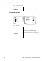
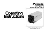
Introduction
The Ignite SDC/HDC robotic camera (Figure 1) is a compact, fully-integrated, remote-control camera designed for worldwide Broadcast and
high-end ProAV applications.
8492_01_r0
Figure 1. Ignite SDC/HDC Robotic Camera
Both SDC and HDC models feature internet protocol (IP) control, converged pan/tilt/focus/zoom operation for seamless on-air movements,
fast pan and tilt speed (90°/s maximum), 300 location presets, 600 seconds
of movement recalls, super-quiet operation <30 dBm @ 1 m, integrated
dual-color light-emitting diode (LED) tally light, optional JSC-2300 SHOT
Director™ robotics/camera controller, optional 17” high-brightness
through-the-lens (TTL) prompter assembly, and optional inverted
mounting for ceiling and track installations.
The SDC (standard definition camera) model features three 2/3” interline,
supersensitive charge-coupled devices (CCD), switchable 4:3/16:9 aspect
ratio, serial digital interface (SDI) and analog composite video outputs, 850
lines of resolution, and 62 dB NTSC/61 dB PAL S/N ratio.
Ignite SDC/HDC Robotic Camera Instruction Manual
17
Section 1 — Overview
The HDC (high definition camera) model features three high-sensitivity
2/3” interline transfer - charge-coupled devices (IT-CCD), switchable
720p/1080i support for global HD formats (1080/60i/59.94i/50i/30p/
25p/24p and 720/60p/59.94p/50p), multi-mode (NTSC/PAL) support,
sensitivity of F10.0 at 2,000 lux, and S/N ratio of 54 dB.
Hardware Description
Note
To order SDC/HDC Robotic Camera hardware and accessories listed in this
manual, refer to Contacting Grass Valley on page 4.
SDC/HDC robotic cameras contain a camera block with integrated tally
light, mounted on a robotic pan/tilt head and pedestal mount. HDC
models come with either premium or standard lens. A TTL prompter is also
provided with select SDC/HDC models.
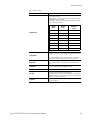
Ignite SDC/HDC robotic camera models and their features are listed in
Table 1.
Table 1. SDC/HDC Robotic Camera Models
Model
Definition
Format
Lens
Prompter
Tally
SDC-3100N
Standard
NTSC
Standard
Not Included
Yes
SDC-3110N
Standard
NTSC
Standard
Through-TheLens (TTL)
Yes
SDC-3100P
Standard
PAL
Standard
Not Included
Yes
SDC-3110P
Standard
PAL
Standard
TTL
Yes
HDC-3200
High-Definition
Multi
Standard
Not Included
Yes
HDC-3210
High-Definition
Multi
Standard
TTL
Yes
HDC-3300
High-Definition
Multi
Premium
Not Included
Yes
HDC-3310
High-Definition
Multi
Premium
TTL
Yes
Additional Equipment (Required)
SHOT Director Robotics/Camera Controller
The JSC-2300 SHOT Director™ robotics/camera controller is a unique,
multiple-camera control device combining pan/tilt and CCU control. The
SHOT Director provides professional-quality, fingertip control of up to 16
Ignite SDC/HDC robotic cameras.
Note
18
At least one JSC-2300 SHOT Director™ robotics/camera controller is
required to operate up to 16 cameras.
Ignite SDC/HDC Robotic Camera Instruction Manual
Optional Mounting Hardware
Ethernet Hub
An Ethernet hub, (10/100/1000 Base TX, auto-sensing) is required to
connect up to 16 Ignite SDC/HDC robotic cameras to a JSC-2300 SHOT
Director robotics/camera controller.
Optional Mounting Hardware
The following optional mounting hardware is recommended for use with
Ignite SDC/HDC robotic cameras.
•
Tripod
•
Tripod mounting plate
•
Wall mount
•
Environmental dome
Functional Description
Robotic Camera
The SDC/HDC robotic camera receives TCP/IP control inputs (pan/tilt/
zoom/focus) from the JSC-2300 SHOT Director robotics/camera controller
(Figure 2).
Figure 2. SDC/HDC Robotic Camera Functional Block Diagram
SDC/HDC
ROBOTIC CAMERA
JSC-2300
SHOT DIRECTOR
ROBOTIC/CAMERA
CONTROL
TCP/IP
PAN/TILT
ROBOTIC
HEAD
ZOOM,
FOCUS
CTRL,
PWR
LENS
IRIS
SDC/HDC
CAMERA
BLOCK
UP TO 15
ADDED
CAMERAS
G/L, SYNC
(FROM
FACILITY)
VIDEO
EQUIPMENT
TALLY
CONTROL
SDI VIDEO
RED TALLY (ON AIR)
AMBER TALLY (NEXT CAM)
PROMPTER
VGA
Ignite SDC/HDC Robotic Camera Instruction Manual
8492_02_r0
SCRIPT
SERVER
19
Section 1 — Overview
The robotic head processes the pan and tilt inputs and moves the camera to
the commanded location. It passes zoom and focus commands to the lens
assembly. It also provides a communication path between the camera head
and SHOT Director (for configuration and status monitoring), and provides 12 V dc to power the camera block.
The camera block receives 12 V dc power from the robotic head, tally (red
and amber) dry contact control from a tally controller, and facility supplied
gen-lock (sync). The camera provides iris control to the lens assembly,
status and configuration menu access to the SHOT Director (through the
robotic head assembly), and produces SDI video out to station switching
and processing equipment.
Robotic Camera and SHOT Director
Robotic camera control requires connection to a JSC-2300 SHOT Director
robotics/camera controller through a network hub. (Figure 3)
Figure 3. SDC/HDC Robotic Camera and JSC-2300 SHOT Director Functional Block Diagram
CAM TRIG,
PRESETS,
MANUAL
PAN/TILT/
ZOOM/FOCUS
CAM SETTINGS MENU
SDC/HDC
ROBOTIC CAMERA
SHOT DIRECTOR
ROBOTIC/CAMERA
CONTROL
JSC-2300
SHOT
DIRECTOR
SUBNET
HUB
PAN/TILT
ROBOTIC
HEAD
ZOOM,
FOCUS
CTRL,
PWR
LENS
IRIS
SDC/HDC
CAMERA
BLOCK
UP TO 15
ADDED
CAMERAS
(16 TOTAL)
G/L, SYNC
(FROM
FACILITY)
VIDEO
EQUIPMENT
TALLY
CONTROL
SDI VIDEO
RED TALLY (ON AIR)
AMBER TALLY (NEXT CAM)
PROMPTER
VGA
8492_03_r0
SCRIPT
SERVER
The SHOT Director can control up to 16 cameras. It provides the camera
trigger and preset/manual control commands (pan/tilt/zoom/focus) to
the robotic head. Camera presets are created and stored in the SHOT
Director. You can also access and make configuration changes to the
camera block settings menu with the SHOT Director.
20
Ignite SDC/HDC Robotic Camera Instruction Manual
Functional Description
Robotic Camera and Ignite Automated Production Control System
The SDC/HDC robotic camera was designed to operate as an integrated
part of an Ignite automated production control system. (Figure 4).
The Ignite system provides TCP/IP automation control to the JSC-2300
SHOT Director robotics/camera controller, video switcher, tally controller,
and optional Script Viewer devices.
Note
Up to six SHOT Directors and sixteen cameras can be used in an Ignite
system.
Figure 4. Ignite SDC/HDC Robotic Camera Functional Block Diagram
TCP/IP
CONTROL
NETWORK
HUB
(16 PORT)
JSC-2300
SHOT
DIRECTOR
CAM TRIG, PRESETS,
MANUAL PAN/TILT/
ZOOM/FOCUS
CAM SETTINGS MENU
SUBNET
HUB
PAN/TILT
ROBOTIC
HEAD
CONTROL, MOVE CAMERA,
PRESET DATA, STATUS
KAYAK
VIDEO
SWITCHER
TALLY
CONTROL
(GPI DRY
CONTACT)
VIDEO
VIDEO
MONITOR
CAM TRIG, PRESETS,
UP TO 5
MANUAL PAN/TILT/
ADDED
ZOOM/FOCUS
SHOT
DIRECTORS CAM SETTINGS MENU
(6 TOTAL)
ZOOM,
FOCUS
CTRL,
PWR
LENS
IRIS
SDC/HDC
CAMERA
BLOCK
UP TO 15
ADDED
CAMERAS
(16 TOTAL)
G/L, SYNC
(FROM
FACILITY)
SDI VIDEO
SDI VIDEO
RED TALLY (ON AIR)
AMBER TALLY (NEXT CAM)
RED TALLY (ON AIR)
AMBER TALLY (NEXT CAM)
SCRIPT
VGA
VIEWER
(OPTIONAL)
Ignite SDC/HDC Robotic Camera Instruction Manual
PROMPTER
VGA
8492_04_r0
IGNITE
CPU
SDC/HDC
ROBOTIC CAMERA
SHOT DIRECTOR
ROBOTIC/CAMERA
CONTROL
IGNITE
AUTOMATED PRODUCTION CONTROL SYSTEM
(COMPLETE SYSTEM NOT SHOWN)
21
Section 1 — Overview
22
Ignite SDC/HDC Robotic Camera Instruction Manual
Section
2
Installation
Unpacking
Check all parts received against the packing list enclosed with your shipment, and examine the equipment for any shipping damage. Immediately
report any missing or damaged items to the carrier and to your Grass
Valley Service Representative (See Contacting Grass Valley on page 4).
Keep all manuals supplied with your equipment. You will need them to
complete the installation procedures.
Installation Procedures
General
Before you can use your Ignite SDC/HDC robotic camera, you must:
1. Mount the robotic assembly onto a tripod (or other mounting surface).
2. Install the optional prompter onto the robotic pan/tilt head assembly.
3. Install the camera/lens assembly onto the prompter, or directly onto
the robotic pan/tilt head (if the optional prompter was not purchased).
4. Connect cables.
Ignite SDC/HDC Robotic Camera Instruction Manual
23
Section 2 — Installation
Robotic Pan/Tilt Head Assembly
Note
Ignite SDC/HDC robotic cameras are suitable for inverted mounting.
1. Check the selected camera location to ensure that there is enough
clearance (Figure 5) for the fully assembled camera, prompter, and
cables to pan and tilt without obstruction.
If necessary, you can limit pan and/or tilt movement by adjusting the
pan/tilt head soft stops via the SHOT Director controller. Refer to the
JSC-2300 SHOT Director Robotics/Camera Controller Instruction
Manual.
Figure 5. Clearance Diagram
8492_06_r0
Diameter: 24” (0.61 m)
48” (1.22 m) with prompter
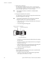
2. On the stationary ring at the top of the pedestal mount (Figure 6), locate
the zero-degree (pan) position labeled FRONT. Point the FRONT label
in the direction that best reflects the center of travel in which the camera
will be used (usually the center of the room).
Figure 6. Robotic Pan/Tilt Head Assembly
Front
Robotic
pan/tilt
head
8” Pedestal
mount
24
Zero degree
(Pan)
reference
8492_05_r0
Camera mount
L-bracket
Ignite SDC/HDC Robotic Camera Instruction Manual
Installation Procedures
CAUTION Ensure that the selected mounting surface and hardware can safely support
the weight of a fully assembled unit (approximately 55 lbs (29.95 kg)).
3. If ceiling/inverted mounting is required:
•
Remove the L-bracket, rotate it 180 degrees, then re-attach it to the
robotic pan/tilt head.
•
Attach a safety wire or chain, that can support the 55 lb (29.95 kg)
weight of the fully assembled unit to one of the bolts in the pedestal
mount flange and secure the other end to a rigid part of the ceiling/
mounting location.
4. Attach the robotic pan/tilt head assembly to the selected mounting
location. Use the four mounting holes in the pedestal mount flange as
shown in Figure 7.
Ignite SDC/HDC Robotic Camera Instruction Manual
25
Section 2 — Installation
Figure 7. Robotic Pan/Tilt Head Mounting
Ceiling Mount
Safety Wire
Tripod Mount
L-bracket must be inverted
Tripod
adapter
plate
8492_07_r0
Tripod
26
Ignite SDC/HDC Robotic Camera Instruction Manual
Installation Procedures
Prompter Adapter Plate (Optional)
Note
The prompter assembly is supported by a mounting plate that sits beneath
the camera assembly.
1. Attach camera adapter plate to prompter adapter plate (Figure 8).
Figure 8. Prompter and Camera Adapter Plates
Mounting
plate
rods
Camera
adapter
plate
Prompter
adapter
plate
8492_08_r0
Front
2. Attach the main body of the prompter adapter plate to the robotic pan/
tilt head assembly L-bracket so that the T-bolt end of the two rods
attached to the mounting plate extend to the front of the robotic pan/
tilt head assembly.
Ignite SDC/HDC Robotic Camera Instruction Manual
27
Section 2 — Installation
Camera/Lens Assembly
1. Ensure camera/lens assembly is oriented toward the front of the pan/
tilt head assembly.
2. Mount the camera/lens assembly to the camera adapter plate (if
installing prompter), or directly to the robotic pan/tilt head assembly
L-bracket with two 3/8-16 x 0.5” socket head screws.
Figure 9. Camera/Lens Assembly Mounting
Flat washers
8492_70_r0
Camera mounting screws
(3/8-16 x 0.5” socket head)
28
Ignite SDC/HDC Robotic Camera Instruction Manual
Installation Procedures
Prompter (Optional)
1. Slide extrusion slots onto mounting plate rods and rotate rods to
tighten (Figure 10). Mounting plate rods slide into the back of the
extrusion where two slots provide alternative vertical positions for the
prompter. The rods attach to the extrusion using a T-bolt that is
tightened by turning the rod.
492_09_r0
Figure 10. Extrusion
2. Rotate the drop plates to the orientation shown in Figure 11.
492_10_r0
Figure 11. Drop Plates
3. Attach drop plates to extrusion and tighten red fixing screws. A choice
of mounting holes are provided to raise and lower the monitor in
relation to the hood to prevent the outer edge of the TFT screen from
appearing in the shot.
4. Attach the hood to the extrusion and rotate hood columns to tighten.
5. Move prompter unit back on the support rods until the lens is nearly
touching the glass and lock in position with small locking levers.
6. Slide the whole prompter assembly back on the mounting plate rods to
obtain best possible balance of the pan/tilt L-bracket. Attach
counterweights if necessary.
Ignite SDC/HDC Robotic Camera Instruction Manual
29
Section 2 — Installation
System Interconnection
Use Figure 12 and the following steps to connect the camera, lens, pan/tilt
head, and prompter assemblies to a JSC 2300 SHOT Director controller and
an Ignite system. If you are not connecting to an Ignite system use the following steps and Figure 13.
Figure 12. Interconnect (with Ignite) Diagram
SDC/HDC ROBOTIC CAMERA
MAINS
VGA IN
SENSOR IN
HIROSE CIRC
HARD
WRED
HIROSE CIRC
G/L BNC
HARD
WRED
VID OUT
DB15
HD15/
SCSI-50
GEN-LOCK
POWER
POWER
HARD
WIRED
CAT-5
FACILITY PROVIDED
EQUIPMENT
VIDEO
CAT-5 VIDEO
VIDEO
COM
PREV
VGA
OUT
VIDEO
MONITOR
RED (PROGRAM) TALLY
TALLY COMMON
GEN-LOCK
(FACILITY
PROVIDED)
AMBER (PREVIEW) TALLY
8492_11_r0
PROG
CAT-5
CAT-5
PROMPTER
48 VDC PWR
SUPPLY
KAYAK AUX
VIDEO OUT
SWITCHER
SCRIPT
VIEWER
IRIS
ZOOM/FOCUS
ZOOM/FOCUS
DIN8
IP CONTROL
CAT-5
CAT-5
CAT-5
IP CONTROL
IP CONTROL
IP CONTROL
TALLY
CTRLR
LENS
CAM
CTRL/PWR
ENET HUB
CAT-5
CAT-5
P/O IGNITE LIVE
PRODUCTION CONTROL
IP CONTROL
SYSTEM
30
CAMERA
BLOCK
IP CONTROL
IP CONTROL
IGNITE
CPU
CAT-5
CAT-5
CAT-5
CAT-5
PAN/TILT
HEAD
RED TALLY OPTICAL SENSOR
DB9
SUBNET
HUB
CAT-5
SHOT
DIRECTOR
AMP CIRC
SHOT
DIRECTOR
Ignite SDC/HDC Robotic Camera Instruction Manual
System Interconnection
Figure 13. Interconnect (without Iignite System) Diagram
SDC/HDC ROBOTIC CAMERA
IRIS
ZOOM/FOCUS
MAINS
HARD
WIRED
DIN8
GEN-LOCK
ZOOM/FOCUS
POWER
VGA IN
PROMPTER
SENSOR IN
HARD
WRED
CAM
CTRL/PWR
IP CONTROL
HIROSE CIRC
LENS
HIROSE CIRC
G/L BNC
VID OUT
HARD
WRED
HD15/
SCSI-50
DB15
CAT-5
CAT-5
CAMERA
BLOCK
POWER
IP CONTROL
PAN/TILT
HEAD
RED TALLY OPTICAL SENSOR
DB9
SUBNET
HUB
CAT-5
CAT-5
SHOT
DIRECTOR
AMP CIRC
SHOT
DIRECTOR
48 VDC PWR
SUPPLY
FACILITY PROVIDED
EQUIPMENT
VIDEO AUX
SWITCH OUT
VIDEO
VIDEO
VIDEO
PROG
COM
PREV
SCRIPT
VIEWER
RED (PROGRAM) TALLY
TALLY COMMON
GEN-LOCK
(FACILITY
PROVIDED)
AMBER (PREVIEW) TALLY
VGA
OUT
8492_11_r0
TALLY
CTRLR
VIDEO
MONITOR
WARNING Ensure mains power is OFF before connecting or disconnecting any
cables, cords, or wires.
Robotic Pan/Tilt Head
1. Connect a CAT-5 cable (not supplied) between the pan/tilt head
assembly and the subnet hub.
2. Connect the zoom/focus cable hirose circular connector to the lens
assembly and the DB-9 connector to the pan/tilt head.
Camera/Lens Assembly
1. Connect the camera control and power harness from the camera block
to the pan/tilt head (DB15).
Ignite SDC/HDC Robotic Camera Instruction Manual
31
Section 2 — Installation
2. Connect an SDI video cable (not supplied) from the camera block to a
studio monitor or video switcher (with studio monitor output).
3. If using a video switcher, connect genlock to the camera block.
4. Connect the Iris control cable from the lens assembly to the camera
block.
5. Connect the unterminated tally wires from the camera block to a tally
controller using 16AWG wire, or provide contact closure control. Tally
control wiring should not exceed 200’ (60.96 m).
Prompter (Optional)
1. Connect a VGA video cable (not supplied) between the prompter and
the script generator.
2. Attach the prompter tally optical sensor to the camera block tally light
cover.
Power
1. Connect the 48 V dc power cord to the pan/tilt head assembly
(Amphenol circular) and the 48 V dc power supply (DIN8). Then
connect the power supply to Mains power.
2. Attach the Mains power cord to the prompter.
32
Ignite SDC/HDC Robotic Camera Instruction Manual
Section
3
Operation
Operating Procedure
1. Turn on all equipment power.
WARNING Ensure personnel and obstacles are clear of the camera during power-up.
The robotic head will automatically rotate to the preset zero degree pan
and tilt location.
Note
The camera robotics may make some noise for the first few hours of operation. This is due to a special type of grease that will seat into the gears to
provide long life lubrication of the mechanical components. The noise should
abate soon after the camera is put into operation.
2. Adjust the camera.
Use the SHOT Director to adjust the camera.
Refer to the JSC-2300 SHOT Director Robotics/Camera Controller
Instruction Manual for procedures and Appendix A-SD (NTSC) Camera
Block, Appendix B-SD (PAL) Camera Block, or Appendix C-HD Camera
Block for adjustment options.
You should adjust the following items the first time the camera is used.
a. Camera ID and IP address.
The pan/tilt head and JSC-2300 SHOT Director are factory set to
default IP addresses to allow the units to communicate initially. If
you are connecting multiple cameras, you will need to set each
camera to a unique ID and IP address using the JSC-2300 SHOT
Director. Refer to Appendix D-Robotic (Pan/Tilt Head) for default and
recommended IP addresses and camera IDs.
b. White balance adjustment.
This adjustment is needed when the camera is used for the first
time, after leaving it unused for a long time, or when the lighting
condition or brightness change.
Note
After adjusting the white balance, re-adjustment is not needed under the
same conditions.
Ignite SDC/HDC Robotic Camera Instruction Manual
33
Section 3 — Operation
c. Black balance adjustment.
This adjustment is needed when the camera is used for the first
time, after being unused for a long time, or when the ambient temperature changes significantly (i.e. seasonal changes).
Note
After adjusting the black balance, re-adjustment is not needed under the
same conditions.
d. Flange back adjustment for zoom lens
This adjustment is used to set the focus range of the zoom lens from
maximum (telephoto) to wide angle.
Note
This adjustment is performed at the factory and will typically not need to be
performed in the field, unless it is necessary to change the lens.
•
Fully open the iris by shooting a dark object from a distance of
at least 6.6 ft (2 m).
•
Loosen the flange back fixing knob.
Figure 14. Zoom Lens Adjustments
Focus ring
Flange back fixing knob
Flange back adjust ring
•
Set the lens to maximum zoom and adjust the focus by turning
the focus ring.
•
Set the lens to widest angle and adjust the focus by turning the
flange back adjust ring.
•
Repeat adjustment of focus ring and flang back adjust ring until
the focus is adjusted through the entire zoom range.
•
Tighten the flange back fixing knob.
e. Gen-lock adjustment.
When multiple cameras are used, or the camera is combined with
other equipment, do the following.
•
34
Connect an external gen-lock synchronization signal (black
burst output) to the camera G/L input.
Ignite SDC/HDC Robotic Camera Instruction Manual
Operating Procedure
Note
The HDC camera accepts SD and HD synchronizing signals. HD synchronizing signals may require different test equipment and may display differently than signals shown in Figure 15.
•
Using a two-channel oscilloscope, observe the gen-lock input
and camera video output waveforms.
•
Match the horizontal phases of the gen-lock in and video out
signals (Figure 15), by adjusting the camera H-Phase setting of
the GEN-LOCK or G/L menu.
Figure 15. Gen-Lock Horizontal Phase Adjustment Waveform
Video signal
Horizontal phase
8492_71_r0
Gen-lock signal
3. Adjust the lighting for the object.
4. Start shooting.
•
Refer to the Ignite Live Production Control System User Manual for
automated camera control procedures.
•
Refer to the JSC-2300 SHOT Director Robotics/Camera Controller
Instruction Manual if you want to:
•
Control the camera manually
•
Create and save presets
•
Change camera settings
5. After shooting, turn off all equipment power.
Ignite SDC/HDC Robotic Camera Instruction Manual
35
Section 3 — Operation
36
Ignite SDC/HDC Robotic Camera Instruction Manual
Section
4
Service
General
Ignite SDC/HDC robotic cameras contain no user-serviceable parts. Refer
any servicing to qualified service personnel.
Troubleshooting
Should problems occur with the Ignite SDC/HDC robotic camera, please
refer to the following troubleshooting matrix (Table 2). If questions or
problems still exist after troubleshooting, please contact your authorized
Grass Valley reseller or contact Grass Valley Customer Support directly.
(See Contacting Grass Valley on page 4.).
Table 2. Troubleshooting (Problem/Cause/Solution) Matrix
Problem
Power
Cause
Solution
Mains power OFF.
Energize Mains power
Power supply not connected to Mains
Connect power supply to Mains
Power supply failure
If power supply LED is NOT illuminated, replace the power supply.
Power supply not connected to pan/
tilt head.
Ensure power supply is properly connected to the pan/tilt head amphenol
circular connector.
Pan/tilt head failure.
Use the SHOT Director to pan/tilt the
camera.
If the pan/tilt head responds properly,
continue to the next possible cause.
If the pan/tilt head does not respond,
replace the pan/tilt head.
Communication
Ignite SDC/HDC Robotic Camera Instruction Manual
Pan/tilt head not connected to camera
block.
Ensure the DB15 connector on the
pan/tilt head is connected to the
HD15 or SCSI-50 connector on the
camera block.
Camera block failure.
If the camera block POWER LED is not
illuminated, replace the camera/lens
assembly.
No power to SHOT Director, network
hub, pan/tilt head, or camera.
Ensure all devices are powered.
37
Section 4 — Service
Table 2. Troubleshooting (Problem/Cause/Solution) Matrix
Problem
Cause
SHOT Director or hub communication
failure.
No traffic indicated on the network
hub front panel LEDs.
Solution
Ensure all devices are powered.
Check CAT5 cable between SHOT
Director and hub.
Use crossover cable between SHOT
Director and pan/tilt head (no hub).
Troubleshoot SHOT Director and/or
hub. (Refer to JSC-2300 SHOT Director Robotics Controller Instruction
Manual).
Pan/tilt head communication failure.
Ensure all devices are powered,
Verify that pan/tilt head does not
respond to pan, tilt, zoom, or focus
commands,
Verify traffic indicated on network hub
front panel LEDs
Check CAT5 cable between hub and
pan/tilt head.
Verify correct IP address setup for
pan/tilt head and SHOT Director
(Refer to JSC-2300 SHOT Director
Robotics Controller Instruction Manual).
CAUTION Contact Customer Service before pressing
the RESET switch on the pan/tilt head.
Press the pan/tilt head RESET switch
(Item 2, Figure 74 on page 107) to set
the pan/tilt factory default IP address
(192.168.0.126) and subnet mask
(255.255.255.0). Then set the SHOT
Director to default address
192.168.0.100 (Refer to JSC-2300
SHOT Director Robotics Controller
Instruction Manual).
Replace pan/tilt head.
Camera block communication failure.
Ensure the DB15 connector on the
pan/tilt head is connected to the
HD15 or SCSI-50 connector on the
camera block.
(HDC Only).
Access the Setting menu using the
menu switch on the back of the HD
camera block (Appendix C-HD Camera Block). Ensure that the protocol is
set to 4.
Replace camera/lens assembly.
Robotics
Pan/tilt head will not pan, tilt or both.
Verify that the pan/tilt head searches
for home (zero pan and zero tilt) at
power up.
Replace pan/tilt head.
Video
No video
Check video cable connected to back
of camera block.
Replace camera/lens assembly.
38
Ignite SDC/HDC Robotic Camera Instruction Manual
Troubleshooting
Table 2. Troubleshooting (Problem/Cause/Solution) Matrix
Problem
Cause
Poor quality video
Solution
Check video cable connected to back
of camera block.
Ensure DB9 connector at pan/tilt head
is connected and that the zoom/focus
cable is connected to the lens assembly.
Ensure the Iris cable from the lens
assembly is connected to the hirose
circular connector at the back of the
camera block.
Use the SHOT Director to access the
camera Settings menu and verify all
menu selections. Refer to the JSC2300 SHOT Director Robotics Controller Instruction Manual and
Appendix A-SD (NTSC) Camera
Block, Appendix B-SD (PAL) Camera
Block, or Appendix C-HD Camera
Block.
Replace camera/lens assembly.
Tally
Tally does not illuminate
Ensure the tally light is properly connect to a tally controller.
Replace camera/lens assembly.
Ignite SDC/HDC Robotic Camera Instruction Manual
39
Section 4 — Service
40
Ignite SDC/HDC Robotic Camera Instruction Manual
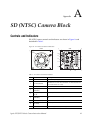
Appendix
A
SD (NTSC) Camera Block
Controls and Indicators
SD (NTSC) camera controls and indicators are shown in Figure 16 and
described in Table 3.
Figure 16. SD Camera Controls and Indicators
FRONT
REAR
3
4
1
ZOOM/FOCUS
2
14
13
SDI
OUT
1
5
12
11
6
SDI
OUT
2
7
9
8492_12_r0
10
8
Table 3. SD Camera Controls and Indicators
Item Name
Description
1
Lens mount
2/3” Standard bayonet type (B4) mount.
2
Lens fixing ring knob
Rotate the lens fixing ring knob counterclockwise and remove the lens mount
cap. Mount the lens on the camera and rotate the lens fixing ring knob clockwise in order to fix the lens securely.
3
Zoom/Focus connector
Not Used.
4
Video Output connector
(VIDEO OUT)
Composite video output.
5
G/L Input connector
(G/L IN)
Gen-lock input.
6
I/F Remote connector
(I/F REMOTE)
Input terminal dedicated to control signals from an optional remote control
box.
7
Iris connector (IRIS)
Input terminal for lens with an iris control function.
8
DC 12 V input connector
(DC 12V IN)
12 V dc input.
9
Power indicator
Red LED lamp lights when DC power is supplied to the camera.
Ignite SDC/HDC Robotic Camera Instruction Manual
41
Appendix A — SD (NTSC) Camera Block
Table 3. SD Camera Controls and Indicators
Item Name
10
SDI OUT 1 and 2
Description
SDI video outputs (SDI Option card)
When the camera is in shooting mode (menu not displayed), the color bar and
shooting conditions are alternately indicated by pressing the switch.
11
NO/BAR switch (NO/BAR/–) With the Main Menu displayed, you can scroll down to any Sub Menu.
With a Sub Menu displayed, you can reduce the value of any setting.
12
YES/ABC switch
(YES/ABC/+)
When the camera is in shooting mode (menu not displayed), the automatic
black balance control can be set with this switch.
With the Main Menu displayed, you can scroll up to any Sub Menu.
With a Sub Menu displayed, you can increase the value of any setting.
13
ITEM/AWC switch
(ITEM/AWC/S)
When the camera is in shooting mode (menu not displayed), the automatic
white balance control can be set with this switch.
With a menu displayed, any item can be selected by pressing this switch.
14
MENU switch (MENU/A)
A menu will appear on the monitor screen when this switch is pressed for
about 5 seconds. This item can be selected by pressing the switch while the
menu is on the screen.
15
Tally light (located on top of
camera body, but not illustrated)
Dual-color LED
Red - On Air
Amber - Next Camera
Requires dry contact tally control
Menu Selections
You can adjust camera settings via on-screen menus by using the controls
on the back of the camera block or by using the JSC-2300 SHOT Director
robotics/camera controller. These adjustments should be performed by
qualified technical personnel only. If your system includes a JSC-2300
SHOT Director, always use the JSC-2300 SHOT Director LCD menus to
make these adjustments.
Use Mode Setting
The camera has four use modes, and various functions for four use modes
have been preset. Functions can be set as best suited to each use mode.
Note
Cameras come from the factory set in User Mode, which allows the greatest
flexibility of settings. Other modes have many of the settings pre-determined
which may or may not work in a particular application.
Halogen mode
Suited to indoor shooting, such as at weddings, parties, lecture meetings,
events, etc. Settings can be changed using a simple menu.
42
Ignite SDC/HDC Robotic Camera Instruction Manual
Menu Selections
Fluorescent mode
Suited to indoor shooting under fluorescent lighting. Settings can be
changed using a simple menu.
Outdoor mode
Suited to outdoor shooting. Settings can be changed using a simple menu.
User mode
Settings can be changed using a detail menu.
Setting by Camera
1. Turn the camera on while keeping the MENU switch (Figure 16)
depressed.
2. The use mode setting menu (Figure 17) appears on the monitor screen
and one of the use mode blinks .
8492_13_r0
Figure 17. Use Mode Setting Menu
3. Press the MENU switch, ITEM/AWC switch, or NO/BAR switch to let
the desired use mode blink.
•
MENU switch: The blinking item moves up one.
•
ITEM/AWC switch, NO/BAR switch: The blinking item moves down
one.
4. Press the YES/ABC switch. The blinking use mode comes into effect.
After the use mode setting menu is shown for about 5 seconds, the
camera returns to ready and operates in the selected use mode.
Ignite SDC/HDC Robotic Camera Instruction Manual
43
Appendix A — SD (NTSC) Camera Block
Menu Item Setting
Each of the four use modes of the camera has a main menu (example shown
in Figure 18).
Figure 18. Main Menu - Halogen, Fluorescent, Outdoor Mode
Use mode
8492_14_r0
Blinking
•
Each item of the main menu has a submenu, which consists of several
settings.
•
These settings have been preset to the optimum values to suit each use
mode, and can be changed to suit actual shooting conditions.
1. Keep the MENU switch depressed for 5 seconds or more. The main
menu appears on the monitor screen.
2. Each time the MENU switch, ITEM/AWC switch, or NO/BAR switch
is pressed, the blinking item moves up or down.
3. When the YES/ABC switch is pressed after selecting the desired item
to blink, the submenu for the selected item appears on the screen.
4. Select the desired item to be changed in its settings using the MENU
switch and ITEM/AWC switch.
5. Press the YES/ABC switch or NO/BAR switch to change the settings.
6. Select [Return] using the MENU switch and ITEM/AWC, then press
the YES/ABC switch to return to the main menu.
7. After changing the settings, take the following steps. Select [End] using
the MENU switch and ITEM/AWC switch and press the YES/ABC
switch.
Changing the Language Setting
The language on the menu screen can be changed from English to Japanese.
(Factory setting: English)
44
•
Halogen, Fluorescent, Outdoor Mode – Select Japanese in the Language
setting in Other Set submenu.
•
Use Mode – Select Japanese in the Language setting in Other Set2 submenu.
Ignite SDC/HDC Robotic Camera Instruction Manual
Menu Selections
Submenus Overview
The following submenus are for Halogen Mode, Fluorescent Mode, and
Outdoor Mode on the NTSC version of the SD camera.
For User Mode submenus, refer to User Mode Submenus Overview on
page 50.
Brightness Setting
8492_15_r0
Figure 19. Brightness Setting Submenu
Table 4.
Brightness Settings
Selection
Description
Picture Level
(-50 to +50) Convergence level of AUTO IRIS/AUTO GAIN UP/ AUTO ND
(ELC) can be adjusted.
Light PEAK/AVG
(P50 to A50) The ratio of AUTO IRIS/AUTO GAIN up/AUTO ND (ELC)
detected peak to average can be adjusted within a predetermined range.
Light Area
A photometric measurement method can be selected for AUTO IRIS/AUTO
GAIN UP/AUTO ND (ELC).
ALL: All the screen area is measured.
Center: The screen is measured mainly in the center area, about
one-third of both the top and bottom and one-third of both the right
and left portions of the screen are excluded from measurement.
Top Cut: About one-third of the top part of the screen is excluded
from measurement.
BTM Cut: About one-third of the bottom portion of the screen is
excluded from measurement.
R/L Cut: About one-third of both the right and left portions of the
screen are excluded from measurement.
Auto ND (ELC)
OFF: Luminance is not automatically adjusted by the electronic shutter.
ON: The electronic shutter is controlled to automatically adjust the luminance.
*ON is automatically selected when the Shutter Speed on the submenu
[Other Set] is set to [Auto ND].
OFF is selected when other than [Auto ND] is selected.
Auto Gain Up
OFF: The light quantity is not adjusted automatically.
ON: The light quantity is adjusted automatically. The maximum to
which the gain can be increased using the Auto Gain Up function is
selected by the AGC Max Gain setting.
AGC Max Gain
(6dB, 12dB, 18dB, 24dB, N/Eye L, N/Eye H) This is used to set the maximum amount to which the gain can be increased when “ON” has been
selected as the Auto Gain Up setting.
Ignite SDC/HDC Robotic Camera Instruction Manual
45
Appendix A — SD (NTSC) Camera Block
Table 4.
Brightness Settings
Selection
Description
Manu Gain Up
Manual setting is possible only when the Auto Gain Up setting is “OFF”.
0 dB: 0 dB should be selected in normal cases.
1 dB - 30 dB: Use this range if sufficient video output cannot be obtained
even when the lens iris is opened in shooting dark scenes.
N/Eye L (Night Eye L): Use this mode if sufficient video output can not be
obtained even if 30 dB gain up should be selected.
N/Eye H (Night Eye H): Use this setting if it is not possible to achieve a satisfactory video output even at the Night Eye L setting.
Pedestal
(-150 to +150) The black level (pedestal) of the luminance (Y) signal can
be set. Used in adjusting the black levels of two or more cameras.
Color Setting
8492_16_r0
Figure 20. Color Setting Submenu
Table 5. Color Settings
46
Selection
Description
Chroma Level
(-3 to +3) Chroma Level can be decreased or increased to any of three levels each.
Flesh Tone
(-3 to +3) Skin color can be decreased or increased to any of three levels
each.
White Bal
ATW: The white balance is automatically adjusted to be always right.
AWC A, AWC B: Once the white balance is adjusted with the ITEM/
AWC switch on the back of the camera, it is no longer necessary to
set the white balance again if you simply select AWC A or AWC B,
provided that the camera is used under the same conditions. Fine
color adjustment can be made after setting AWC by red/blue gain
adjustment in user mode.
P SET 3200 K: The white balance is adjusted to 3200 K illumination.
P SET 5600 K: The white balance is adjusted to 5600 K illumination.
ATW Speed
(Slow 2, Slow 1, Mid, Fast 1, Fast 2) ATW Speed can be set.
Ignite SDC/HDC Robotic Camera Instruction Manual
Menu Selections
G/L, Color Bar Setting
8492_17_r0
Figure 21. GL, Color Bar Setting Submenu
Table 6. Color Bar Settings
Selection
Description
H Phase
(-206 to +49) Horizontal phase can be adjusted when a genlock signal is
supplied.
SC Coarse
(1, 2, 3, 4) Coarse adjustment of sub carrier phase can be made when a
genlock signal is supplied.
SC Fine
(-511 to +511) Fine adjustment of sub carrier phase can be made when a
genlock signal is supplied.
Color Bar Set
(0.0 IRE, 7.5 IRE) The setup level of color bar can be adjusted.
Color Bar Set2
(0.0 IRE, 7.5 IRE) Set 0.0 IRE for the SDI card.
Sharpness (DTL) Setting Overview
8492_18_r0
Figure 22. Sharpness (DTL) Settings Submenu
Table 7. Sharpness (DTL) Settings
Selection
Description
DTL Select
(Sharpness, Super DTL) If contour correction is not sufficient at the Sharpness position when Detail Level setting is set to Low or High, select the
Super DTL position.
*Neither Sharpness nor Super DTL is valid for contour correction if Detail
Level setting is in the OFF position.
Level
(OFF, Low, High) Detail level can be adjusted when Detail Select setting is
at Sharpness. Super DTL level can be adjusted when it is at Super DTL.
Noise Suppress
(OFF, Low, High) Screen noise can be reduced when Detail Level setting is
at High or Low.
Ignite SDC/HDC Robotic Camera Instruction Manual
47
Appendix A — SD (NTSC) Camera Block
Table 7. Sharpness (DTL) Settings
Selection
Description
Clean DNR
(OFF, Low, High) This enables the clean DNR effect to be selected.
Flesh Noise Sup.
(OFF, Low, High) Flesh noise is suppressed in two steps when the Level
setting is at High or Low.
Other Settings Overview
8492_19_r0
Figure 23. Other Settings Submenu
Table 8. Other Settings
Selection
Description
Contrast (Gamma)
(Low, Mid, High) Contrast can be adjusted to any of three levels.
OFF: Electronic shutter is turned off.
1/100, 1/250, 1/500, 1/1000, 1/2000, 1/4000, 1/10000:
Electronic shutter operates at one of these speeds as selected.
Shutter Speed
S/Scan (Synchro Scan): Electronic shutter operates at the speed set with
the Synchro Scan setting.
Auto ND: Electronic shutter is controlled to automatically adjust the luminance.
*Flickering may increase at Auto ND under fluorescent lights. *Auto ND is
automatically selected if Auto ND (ELC) setting is set to ON.
48
Ignite SDC/HDC Robotic Camera Instruction Manual
Menu Selections
Table 8. Other Settings
Selection
Description
(60.34 Hz to 15.75 kHz) This setting is possible only when the Shutter
Speed setting is at S/Scan.
Horizontal bar noise can be reduced by synchro-scan adjustment in shooting workstation scenes, for example.
*For luminance settings at each shutter speed and synchro-scan shutter
speed, refer to the following table.
Synchro Scan
V Resolution
Shutter
Speed
Synchro
Scan
Required
Luminance
Ratio
OFF
-
1
1/100
100.3 Hz
2
1/250
250.0 Hz
4
1/500
492.2 Hz
8
1/1000
984.4 Hz
16
1/2000
1.969 kHz
32
1/4000
3.938 kHz
64
1/10000
7.875 kHz
160
Normal: Normal image. (CCD storage will be by field storage. Recommended for general use because sensitivity will decrease at the Fine setting.
Fine: Vertical resolution increases. (Vertical resolution is raised without
increasing residual images by frame storage and electronic shutter.)
Baud Rate
(1200bps, 2400bps, 4800bps, 9600bps)
Select a communication speed in controlling the camera from the computer.
Component
This enables RGB, Y/Pr/Pb or Y/C to be selected as the component signals
which are to be output from the I/F REMOTE connector.
Aspect Ratio
Aspect ratio can be selected from 16:9 or 4:3.
Fan SW
OFF: Select this setting to stop the fan when its operating sound is found to
be bothersome in a studio or other such environment.
Auto: The temperature is detected automatically, and the fan starts operating when the temperature exceeds approx. 95 ºF (35 ºC). Under normal circumstances, the “Auto” setting is used.
Language
English: Menu screen is displayed in English.Japanese: Menu screen is
displayed in Japanese.
Ignite SDC/HDC Robotic Camera Instruction Manual
49
Appendix A — SD (NTSC) Camera Block
User Mode Submenus Overview
Iris, Shutter, Gain Settings Overview
8492_20_r0
Figure 24. Iris, Shutter, Gain Settings Submenu
Table 9. Iris, Shutter, Gain Settings
50
Selection
Description
Picture Level
(-50 to +50) Convergence level of AUTO IRIS, AUTO GAIN UP, ELC can be
adjusted.
Light PEAK/AVG
(P50 to A50) The ratio of AUTO IRIS, AUTO GAIN UP, ELC detected peak to
average can be adjusted within a range.
Light Area
A photometric measurement method can be selected for AUTO IRIS, AUTO
GAIN UP, ELC.
All: All the screen is measured.
Center: The screen is measured mainly in the center area, about one-third
of both the top and bottom and one-third of both the right and left portions
of the screen are excluded from measurement.
Top cut: About one-third of the top portion of the screen is excluded from
measurement.
BTM cut: About one-third of the bottom portion of the screen is excluded
from measurement.
R/L cut: About one-third of both the right and left portions of the screen are
excluded from measurement.
Auto Iris Adjust
(ON, OFF)
Shutter Mode
Step: Electronic shutter operates at the speed selected by the Step/Synchro
setting.
S/Scan (Synchro Scan): Electronic shutter operates at the speed selected
in Step/Synchro setting.
ELC: Electronic shutter is controlled to automatically adjust the luminance.
*If Frame 1 is selected in Field/Frame setting, Shutter Mode setting cannot
be added.
Ignite SDC/HDC Robotic Camera Instruction Manual
Menu Selections
Table 9. Iris, Shutter, Gain Settings
Selection
Description
This setting is possible only when Step or Synchro Scan is selected in
Shutter Mode setting.
When “Step” has been selected as the Shutter Mode setting:
OFF: Electronic shutter is turned off.
1/100, 1/250, 1/500, 1/1000, 1/2000, 1/4000, 1/10000: Electronic shutter
operates at one of these speeds as selected.
When “Synchro Scan” has been selected as the Shutter Mode setting:
60.34 Hz to 15.75 kHz: Bar noise can be reduced by synchro-scan adjustment in shooting workstation scenes, for example.
*For luminance setting at each shutter speed and synchro-scan shutter
speed, refer to the table below.
Step/Synchro
Shutter
Speed
Synchro
Scan
Required
Luminance Ratio
OFF
-
1
1/100
100.3 Hz
2
1/250
250.0 Hz
4
1/500
492.2 Hz
8
1/1000
984.4 Hz
16
1/2000
1.969 kHz
32
1/4000
3.938 kHz
64
1/10000
7.875 kHz
160
Gain
Auto: The light quantity is adjusted automatically.
0 dB: 0dB should be selected in normal cases.
1 dB to 30 dB: Use this range if sufficient video output cannot be obtained
even when the lens iris is opened in shooting dark scenes.
N/Eye L (Night Eye L): Use this mode if sufficient video output cannot
obtained even if 30 dB gain up should be selected.
N/Eye H (Night Eye H): Use this setting if it is not possible to achieve a satisfactory video output even at the Night Eye L setting.
AGC Max Gain
(6dB, 12dB, 18dB, 24dB, N/Eye L, N/Eye H) This is used to set the maximum gain up when “Auto” has been selected as the gain setting.
Ignite SDC/HDC Robotic Camera Instruction Manual
51
Appendix A — SD (NTSC) Camera Block
Color Settings
8492_16_r0
Figure 25. Color Settings Submenu
Table 10. Color Settings
52
Selection
Description
Chroma Level
(-3 to +3) Chroma Level can be decreased or increased to three levels.
White Bal
ATW: The white balance is automatically adjusted to the optimum position.
AWC A, AWC B: Once the white balance is adjusted with the ITEM/AWC
switch on the back of the camera, it is no longer necessary to set the white
balance again if you simply select AWC A or AWC B, provided that the
camera is used under the same conditions. Fine color adjustment can be
made after setting AWC by red/blue gain adjustment in User Mode.
3200K: The white balance is adjusted to 3200K illumination.
5600K: The white balance is adjusted to 5600K illumination.
ATW Speed
(Slow 2, Slow 1, Mid, Fast 1, Fast 2) ATW Speed can be set.
Pedestal
(-150 to +150) The black level (pedestal) of the luminance (Y) signal can
be set. Used in adjusting the black levels of two or more cameras.
Painting
(-150 to +150)
R Gain, B Gain: Fine adjustment of the white balance can be made after
AWC setting when AWC A or AWC B is selected in White Balance Setting.
The set value returns to ±0 after AWC setting in using the camera alone.
R Pedestal, B Pedestal: Fine adjustment of the black balance can be made
after ABC setting. The set value returns to ±0 after ABC setting in using the
camera alone.
Ignite SDC/HDC Robotic Camera Instruction Manual
Menu Selections
G/L, Color Bar Settings
8492_17_r0
Figure 26. G/L Color Bar Setting Submenu
Table 11. G/L Color Bar Settings
Selection
Description
H Phase
(-206 to +49) Horizontal phase can be adjusted when a genlock signal is
supplied.
SC Coarse
(1, 2, 3, 4) Coarse adjustment of sub carrier phase can be made when a
genlock signal is supplied.
SC Fine
(-511 to +511) Fine adjustment of sub carrier phase can be made when a
genlock signal is supplied.
Color Bar Set
(0.0 IRE, 7.5 IRE) The setup level of color bar can be adjusted.
Color Bar Set2
(0.0 IRE, 7.5 IRE) Set to 0.0 IRE for the SDI card.
Detail Settings
8492_21_r0
Figure 27. Detail Setting Submenu
Table 12. Detail Settings
Selection
Description
(OFF, Low, High) Contour correction quantity can be selected. Detail settings made using the Horizontal/Vertical Detail Level High/Low setting.
Detail
Detail level can be set in horizontal (H) and vertical (V) directions with the
Detail setting at High or
Low.
Whichever the direction, H or V, the set level at High must be at least one
position higher than that
at Low.
H Detail Level H
(L+1 to +63)
V Detail Level H
(L+1 to +31)
Ignite SDC/HDC Robotic Camera Instruction Manual
53
Appendix A — SD (NTSC) Camera Block
Table 12. Detail Settings
Selection
Description
H Detail Level L
(0 to H-1)
V Detail Level L
(0 to H-1)
Detail Band
(1 to 5) A contour correction band can be set with the Detail setting at High
or Low. The higher setting, the finer will be the detail.
Noise Suppress
(1 to 10) Screen noise can be reduced with the Detail setting at High or
Low. If the noise suppress compensation level is set too high, a fine object
will be reproduced less sharply.
Level Dependent
(0% to 25%) Screen noise due to the detail of dark parts of an object can
be reduced. If the Level Dependent setting is set too high, however, hair, for
example, will be reproduced less sharply.
Dark Detail
(0 to 5) The contours of the darker portions of an object can be emphasized. This setting is possible only when the Level Dependent setting is set
to 0%.
Chroma Detail
(0 to 15) The contours of high-hue portions of an object can be emphasized.
Flesh Noise Sup.
(OFF, Low, High) Flesh noise is suppressed in two steps when the Detail
setting is at High or Low.
Precision Detail
(OFF, Low, High) This setting is to narrow detail width and suppress detail
glare.
Color Matrix Settings
8492_22_r0
Figure 28. Color Matrix Setting Submenu
Table 13. Color matrix Settings
54
Selection
Description
B_Mg Gain
Increases or decreases the hue of the intermediate color between blue and
magenta.
B_Mg Phase
Varies the hue of the intermediate color between blue and magenta.
Mg Gain
Increases or decreases the magenta.
Mg Phase
Varies the hue of the magenta.
Mg_R Gain
Increases or decreases the intermediate color between magenta and red.
Mg_R Phase
Varies the hue of the intermediate color between magenta and red.
R Gain
Increases or decreases the red.
R Phase
Varies the hue of the red.
R_YI Gain
Increases or decreases the intermediate color between red and yellow.
R_YI Phase
Varies the hue of the intermediate color between red and yellow
YI Gain
Increases or decreases the intermediate color of yellow.
Ignite SDC/HDC Robotic Camera Instruction Manual
Menu Selections
Table 13. Color matrix Settings
Selection
Description
YI Phase
Varies the hue of the yellow.
YI_G Gain
Increases or decreases the intermediate color between yellow and green.
YI_G Phase
Varies the hue of the intermediate color between yellow and green.
G Gain
Increases or decreases the green.
G Phase
Varies the hue of the green.
G_Cy Gain
Increases or decreases the intermediate color between green and cyan.
G_Cy Phase
Varies the hue of the intermediate color between green and cyan.
Cy Gain
Increases or decreases the cyan.
Cy Phase
Varies the hue of the cyan.
Cy_B Gain
Increases or decreases the intermediate color between cyan and blue.
Cy_B Phase
Varies the hue of the intermediate color between cyan and blue.
B Gain
Increase or decreases the intermediate color between blue and magenta.
B Phase
Varies the hue of the intermediate color between blue and magenta.
Other Settings
8492_19_r0
Figure 29. Other Settings Submenu
Table 14. Other Settings
Selection
Description
Gamma
(0.35 to 0.55) Gamma correction level can be set.
Knee Point
88% to 98%: The level of video signals subject to knee (knee point) can be
set. Dynamic: Knee level is automatically adjusted according to the scene.
White Clip
(95% to 110%) The peak level of video signals to be white-clipped can be
set.
Flare R/G/B
(0 to 100) Flare correction level can be adjusted.
Black Stretch
Black stretch to correct the suppression of black portions at low luminance
can be set to ON or OFF.
Clean DNR
(OFF, Low, High) This enables the clean DNR effect to be selected.
Field/Frame
Field: CCD storage will be by field storage.
Frame 1: Vertical resolution increases in frame storage.
Frame 2: Vertical resolution is raised without increasing residual images
by frame storage and electronic shutter.
Baud Rate
(1200bps, 2400bps, 4800bps, 9600bps) This setting is to select a communication speed in controlling the camera from the computer.
Component
This enables RGB, Y/Pr/Pb or Y/C to be selected as the component signals
which are to be output from the I/F REMOTE connector.
Ignite SDC/HDC Robotic Camera Instruction Manual
55
Appendix A — SD (NTSC) Camera Block
Table 14. Other Settings
Selection
Description
Aspect Ratio
Aspect ratio can be selected from 16:9 or 4:3.
Fan SW
OFF: Select this setting to stop the fan when its operating sound is found to
be bothersome in a studio or other such environment.
Auto: The temperature is detected automatically, and the fan starts operating when the temperature exceeds approx. 95 ºF (35 ºC)
Language
English: Menu screen is displayed in English. Japanese: Menu screen is
displayed in Japanese.
to Return to Initial Settings
1. Select [Initialize Data] on the main menu screen of each Use Mode.
Press the YES/ABC switch, then the [Initialize Data] screen (Figure 30)
shows for about 10 seconds.
8492_23_r0
Figure 30. Initialize Data Screen
2. Press the YES/ABC switch within about 10 seconds to return to the
initial settings (Table 15 and Table 16), the existing settings are
initialized (Figure 31), and the camera returns to main menu
8492_24_r0
Figure 31. Data Initialized Screen
3. If the NO/BAR switch is pressed, or if the YES/ABC switch is not
pressed, within about 10 seconds (Figure 32), and the camera returns to
main menu, then the existing settings are not initialized.
56
Ignite SDC/HDC Robotic Camera Instruction Manual
Menu Selections
8492_25_r0
Figure 32. Data Unchanged Screen
Table 15. Factory preset values for Halogen Mode, Fluorescent Mode, and Outdoor Mode
Item
Halogen mode Fluorescent mode Outdoor mode
Brightness Set
Picture Level
Light PEAK/AVG
Light Area
Auto ND (ELC)
Auto Gain Up
AGC Max Gain
Manu Gain Up
Pedestal
±0
0
Top cut
OFF
OFF
--0 dB
±0
±0
0
Top cut
OFF
OFF
--0dB
±0
±0
0
Top cut
ON
ON
N/Eye H
---40
Color Set
Chroma Level
Flesh Tone
White Bal
ATW Speed
±0
±0
AWC A
---
±0
±0
AWC A
---
±0
±0
ATW
Mid
G/L, Color Bar Set
H Phase
SC Coarse
SC Fine
Color Bar Set
Color Bar Set 2
±0
1
±0
7.5 IRE
0.0 IRE
±0
1
±0
7.5 IRE
0.0 IRE
±0
1
±0
7.5 IRE
0.0 IRE
Sharpness (DTL) Set
DTL Select
Level
Noise Suppress
Clean DNR
Flesh Noise Sup.
Sharpness
HIGH
OFF
OFF
OFF
Sharpness
HIGH
OFF
OFF
OFF
Sharpness
HIGH
OFF
OFF
OFF
Other Set
Contrast (Gamma)
Shutter Speed
Synchro Scan
V Resolution
Baud Rate
Component
Aspect Ratio
Fan SW
Language
Mid
OFF
--Normal
9600 bps
Y/Pr/Pb
16:9
Auto
(English)
Mid
OFF
--Normal
9600 bps
Y/Pr/Pb
16:9
Auto
(English)
Mid
Auto ND
--Normal
9600 bps
Y/Pr/Pb
16:9
Auto
(English)
Ignite SDC/HDC Robotic Camera Instruction Manual
57
Appendix A — SD (NTSC) Camera Block
Table 16. Factory preset values for User Mode
58
Item
User mode
Iris, Shutter, Gain Set
Picture Level
Light PEAK/AVG
Light Area
Auto Iris Adjust
Shutter Mode
Step/Synchro
Gain
AGC Max Gain
±0
0
Top cut
OFF
Step
OFF
0 dB
--+2
AWC A
--±0
Color Set
Chroma Level
White Bal
ATW Speed
Pedestal
Painting:
R Gain
B Gain
R Pedestal
B Pedestal
G/L, Color Bar Set
H Phase
SC Coarse
SC Fine
Color Bar Set
Color Bar Set2
±0
1
±0
7.5 IRE
0.0 IRE
Detail Set 1
Detail
H Detail Level H
V Detail Level H
H Detail Level L
V Detail Level L
Detail Band
Noise Suppress
Level Dependent
Dark Detail
High
20
19
13
8
5
3
0%
0
Detail Set 2
Chroma Detail
Flesh Noise Suppress
Precision Detail
0
OFF
OFF
Color Matrix Set 1
B_Mg Gain
B_Mg Phase
Mg Gain
Mg Phase
Mg_R Gain
Mg_R Phase
R Gain
R Phase
±0
±0
+27
±0
±0
±0
+15
±0
Color Matrix Set 2
R_YI Gain
R_YI Phase
YI Gain
YI Phase
YI_G Gain
YI_G Phase
G Gain
G Phase
±0
±0
+18
+6
±0
±0
+30
+112
Color Matrix Set 3
G_Cy Gain
G_Cy Phase
Cy Gain
Cy Phase
Cy_B Gain
Cy_B Phase
B Gain
B Phase
±0
±0
+44
-15
±0
±0
-20
+36
±0
±0
±0
±0
Ignite SDC/HDC Robotic Camera Instruction Manual
Menu Selections
Table 16. Factory preset values for User Mode
Item
User mode
Other Set 1
Gamma
Knee Point
White Clip
Flare R
Flare G
Flare B
Black Stretch
Clean DNR
0.45
88%
110%
0
0
0
OFF
OFF
Other Set 2
Field/Frame
Baud Rate
Component
Aspect Ratio
Fan SW
Language
Field
9600 bps
Y/Pr/Pb
16:9
Auto
(English)
Ignite SDC/HDC Robotic Camera Instruction Manual
59
Appendix A — SD (NTSC) Camera Block
Specifications
SD camera specifications are listed in Table 17.
Table 17. SD Camera Specifications
60
Power Requirements
12 Vdc 15 W
Optical System
2/3” Prism optical system, F1.4
Pickup Device
2/3” Interline wide CCD
Total Pixels
1020 (H)x505 (V) (About 510000 pixels)
Scanning System
525 lines, 60 fields, 30 flames
SYNC System
Internal: EIA standard
External: BBS or VBS (BNCx1, Dsub 50 Px1)
Video Output
Composite: 1.0 Vp-p/75 Ohm (BNCx1, Dsub 50 Px1)
Y/C Y: 1.0 Vp-p/75 Ohm; C: 0.286 Vp-p/75 Ohm (burst) (Dsub 50 Px1)
Y/Pr/Pb Y: 1.0 Vp-p/75 Ohm; Pr, Pb: 0.7 Vp-p/75 Ohm (Dsub 50 Px1)
RGB G: 1.0 Vp-p/75 Ohm; RB: 0.7 Vp-p/75 Ohm (Dsub 50 Px1)
Std Illumination Color Temp
2,000 lx (F11, 3200K)
Minimum Illumination
0.4 lx (F1.7, Night Eye H)
S/N Ratio
65 dB (Y signal, DTL OFF, gamma OFF, DNR ON)
Horizontal Resolution
850 TV lines (high band DTL ON, center area)
Registration
0.05% (Entire screen, excluding effects of lens)
Aspect Ratio Conversion
16:9, 4:3
Contour Correction
horizontal, vertical (2H)
White Balance
AWC A, AWC B (R/B gain, painting), ATW, 3200K, 5600K preset
Black Balance
Auto (R/B pedestal, painting function)
Chroma Variability
7 levels
Encoding System
Y, R-Y, B-Y
Gain Selection
0 to 30 dB in step, AGC, Night Eye L/H
Electronic Shutter Speed
1/100, 1/250, 1/500, 1/1000, 1/2000, 1/4000, 1/10000, ELC, Synchro
scan (60.34 Hz to 15.75 kHz)
CCD Readout Selection
Field, Flame 1, Flame 2
Color Bars
SMPTE
Lens Mount
2/3” bayonet mount
Lens Diaphragm
Auto, Manual (only with remote control), Adjust On, Off
Selectors
MENU
ITEM/AWC (AWC: when menu screen is not displayed)
YES/ABC (ABC: when menu screen is not displayed)
NO/BAR (BAR: when menu screen is not displayed)
Input/Output Connectors
VIDEO OUT: BNC connector
G/L IN: BNC connector
IRIS: 12 P round connector
DC 12 V IN: DC connector
I/F REMOTE: 50 P Dsub connector
Indicators
Red LED: Power On
Allowable Temperature Range
For storage: –4 °F to 140 °F (–20 °C to +60 °C)
For guaranteeing performance: 41 °F to 95 °F (+5 °C to +35 °C)
For guaranteeing operation: 14 °F to 113 °F (–10 °C to +45 °C)
Allowable Humidity Ranges
For storage: 20% to 90%, for operation: 20% to 90%
Dimensions (WxHxD)
3-5/16”x3-3/4”x7-9/16” (84x95x192 mm)
Weight
2.5 lbs (1.15 kg)
Ignite SDC/HDC Robotic Camera Instruction Manual
Appendix
B
SD (PAL) Camera Block
Controls and Indicators
SD (PAL) camera controls and indicators are shown in Figure 33 and
described in Table 18.
Figure 33. SD Camera Controls and Indicators
FRONT
REAR
3
4
1
ZOOM/FOCUS
2
14
13
SDI
OUT
1
5
12
11
6
SDI
OUT
2
7
9
8492_12_r0
10
8
Table 18. SD Camera Controls and Indicators
Item Name
Description
1
Lens mount
2/3” Standard bayonet type (B4) mount.
2
Lens fixing ring knob
Rotate the lens fixing ring knob counterclockwise and remove the lens mount
cap. Mount the lens on the camera and rotate the lens fixing ring knob clockwise in order to fix the lens securely.
3
Zoom/Focus connector
Not Used.
4
Video Output connector
(VIDEO OUT)
Composite video output.
5
G/L Input connector
(G/L IN)
Gen-lock input.
6
I/F Remote connector
(I/F REMOTE)
Input terminal dedicated to control signals from an optional remote control
box.
7
Iris connector (IRIS)
Input terminal for lens with an iris control function.
8
DC 12 V input connector
(DC 12V IN)
12 V dc input.
9
Power indicator
Red LED lamp lights when DC power is supplied to the camera.
Ignite SDC/HDC Robotic Camera Instruction Manual
61
Appendix B — SD (PAL) Camera Block
Table 18. SD Camera Controls and Indicators
Item Name
10
SDI OUT 1 and 2
Description
SDI video outputs (SDI Option card)
When the camera is in shooting mode (menu not displayed), the color bar and
shooting conditions are alternately indicated by pressing the switch.
11
NO/BAR switch (NO/BAR/–) With the Main Menu displayed, you can scroll down to any Sub Menu.
With a Sub Menu displayed, you can reduce the value of any setting.
12
YES/ABC switch
(YES/ABC/+)
When the camera is in shooting mode (menu not displayed), the automatic
black balance control can be set with this switch.
With the Main Menu displayed, you can scroll up to any Sub Menu.
With a Sub Menu displayed, you can increase the value of any setting.
13
ITEM/AWC switch
(ITEM/AWC/S)
When the camera is in shooting mode (menu not displayed), the automatic
white balance control can be set with this switch.
With a menu displayed, any item can be selected by pressing this switch.
14
MENU switch (MENU/A)
A menu will appear on the monitor screen when this switch is pressed for
about 5 seconds. This item can be selected by pressing the switch while the
menu is on the screen.
15
Tally light (located on top of
camera body, but not illustrated)
Dual-color LED
Red - On Air
Amber - Next Camera
Requires dry contact tally control
Menu Selections
You can adjust camera settings via on-screen menus by using the controls
on the back of the camera block or by using the JSC-2300 SHOT Director
robotics/camera controller. These adjustments should be performed by
qualified technical personnel only. If your system includes a JSC-2300
SHOT Director, always use the JSC-2300 SHOT Director’s LCD menus to
make these adjustments.
Use Mode Setting
The camera has four use modes, and various functions for four use modes
have been preset. Functions can be set as best suited to each use mode.
Halogen mode
Suited to indoor shooting, such as at weddings, parties, lecture meetings,
events, etc. Settings can be changed using a simple menu.
Fluorescent mode
Suited to indoor shooting under fluorescent lighting. Settings can be
changed using a simple menu.
62
Ignite SDC/HDC Robotic Camera Instruction Manual
Menu Selections
Outdoor mode
Suited to outdoor shooting. Settings can be changed using a simple menu.
User mode
Settings can be changed using a detail menu.
Setting by Camera
1. Turn the camera on while keeping the MENU switch (Figure 33)
depressed.
2. The use mode setting menu (Figure 34) appears on the monitor screen
and one of the use mode blinks .
8492_26_r0
Figure 34. Use Mode Setting Menu
3. Press the MENU switch, ITEM/AWC switch, or NO/BAR switch to let
the desired use mode blink.
•
MENU switch: The blinking item moves up one.
•
ITEM/AWC switch, NO/BAR switch: The blinking item moves down
one.
4. Press the YES/ABC switch. The blinking use mode comes into effect.
After the use mode setting menu is shown for about 5 seconds, the
camera returns to ready and operates in the selected use mode.
Ignite SDC/HDC Robotic Camera Instruction Manual
63
Appendix B — SD (PAL) Camera Block
Menu Item Setting
Each of the four use modes of the camera has a main menu (Figure 35).
Figure 35. Main Menu - Halogen, Fluorescent, Outdoor Mode
Use mode
8492_27_r0
Blinking
•
Each item of the main menu has a submenu, which consists of several
settings.
•
These settings have been preset to the optimum values to suit each use
mode, and can be changed to suit actual shooting conditions.
1. Keep the MENU switch depressed for 5 seconds or more. The main
menu appears on the monitor screen.
2. Each time the MENU switch, ITEM/AWC switch, or NO/BAR switch
is pressed, the blinking item moves up or down.
3. When the YES/ABC switch is pressed after selecting the desired item
to blink, the submenu for the selected item appears on the screen.
4. Select the desired item to be changed in its settings using the MENU
switch and ITEM/AWC switch.
5. Press the YES/ABC switch or NO/BAR switch to change the settings.
6. Select [Return] using the MENU switch and ITEM/AWC, then press
the YES/ABC switch to return to the main menu.
7. After changing the settings, take the following steps. Select [End] using
the MENU switch and ITEM/AWC switch and press the YES/ABC
switch.
Submenus Overview
The following submenus are for Halogen Mode, Fluorescent Mode, and
Outdoor Mode on the NTSC version of the SD camera. User Mode submenus are described in User Mode Submenus Overview on page 69.
64
Ignite SDC/HDC Robotic Camera Instruction Manual
Menu Selections
Brightness Setting
8492_28_r0
Figure 36. Brightness Setting Submenu
Table 19.
Brightness Settings
Selection
Description
Iris Level
(-50 to +50) Convergence level of AUTO IRIS/AUTO GAIN UP/ AUTO ND
(ELC) can be adjusted.
Iris PEAK/AVG
(P50 to A50) The ratio of AUTO IRIS/AUTO GAIN up/AUTO ND (ELC)
detected peak to average can be adjusted within a predetermined range.
Iris Area
A photometric measurement method can be selected for AUTO IRIS/AUTO
GAIN UP/AUTO ND (ELC).
ALL: All the screen area is measured.
Center: The screen is measured mainly in the center area, about
one-third of both the top and bottom and one-third of both the right
and left portions of the screen are excluded from measurement.
Top Cut: About one-third of the top part of the screen is excluded
from measurement.
BTM Cut: About one-third of the bottom portion of the screen is
excluded from measurement.
R/L Cut: About one-third of both the right and left portions of the
screen are excluded from measurement.
Auto ND (ELC)
OFF: Luminance is not automatically adjusted by the electronic shutter.
ON: The electronic shutter is controlled to automatically adjust the luminance.
*ON is automatically selected when the Shutter Speed on the submenu
[Other Set] is set to [Auto ND].
OFF is selected when other than [Auto ND] is selected.
Auto Gain Up
OFF: The light quantity is not adjusted automatically.
ON: The light quantity is adjusted automatically. The maximum to which
the gain can be increased using the Auto Gain Up function is selected by
the AGC Max Gain setting.
AGC Max Gain
(6dB, 12dB, 18dB, 24dB, N/Eye L, N/Eye H) This is used to set the maximum amount to which the gain can be increased when “ON” has been
selected as the Auto Gain Up setting.
Manu Gain Up
Manual setting is possible only when the Auto Gain Up setting is “OFF”.
0 dB: 0 dB should be selected in normal cases.
1 dB - 30 dB: Use this range if sufficient video output cannot be obtained
even when the lens iris is opened in shooting dark scenes.
N/Eye L (Night Eye L): Use this mode if sufficient video output can not be
obtained even if 30 dB gain up should be selected.
N/Eye H (Night Eye H): Use this setting if it is not possible to achieve a satisfactory video output even at the Night Eye L setting.
Pedestal
(-150 to +150) The black level (pedestal) of the luminance (Y) signal can
be set. Used in adjusting the black levels of two or more cameras.
Ignite SDC/HDC Robotic Camera Instruction Manual
65
Appendix B — SD (PAL) Camera Block
Color Setting
8492_29_r0
Figure 37. Color Setting Submenu
Table 20. Color Settings
Selection
Description
Chroma Level
(-3 to +3) Chroma Level can be decreased or increased to any of three levels each.
Flesh Tone
(-3 to +3) Skin color can be decreased or increased to any of three levels
each.
White Bal
ATW: The white balance is automatically adjusted to be always right.
AWC A, AWC B: Once the white balance is adjusted with the ITEM/AWC
switch on the back of the camera, it is no longer necessary to set the white
balance again if you simply select AWC A or AWC B, provided that the
camera is used under the same conditions. Fine color adjustment can be
made after setting AWC by red/blue gain adjustment in user mode.
3200 K: The white balance is adjusted to 3200 K illumination.
5600 K: The white balance is adjusted to 5600 K illumination.
ATW Speed
(Slow 2, Slow 1, Mid, Fast 1, Fast 2) ATW speed can be set.
G/L Adjustment Setting
8492_30_r0
Figure 38. G/L Adjustment Setting Submenu
Table 21. G/L Adjustment Settings
66
Selection
Description
H Phase
(-206 to +49) Horizontal phase can be adjusted when a genlock signal is
supplied.
SC Coarse
(1, 2, 3, 4) Coarse adjustment of sub carrier phase can be made when a
genlock signal is supplied.
SC Fine
(-511 to +511) Fine adjustment of sub carrier phase can be made when a
genlock signal is supplied.
Ignite SDC/HDC Robotic Camera Instruction Manual
Menu Selections
Sharpness (DTL) Setting Overview
8492_31_r0
Figure 39. Sharpness (DTL) Settings Submenu
Table 22. Sharpness (DTL) Settings
Selection
Description
DTL Select
(Normal, Super DTL) If contour correction is not sufficient at the Normal
position when Detail Level setting is set to Low or High, select the Super
DTL position.
*Neither Normal nor Super DTL is valid for contour correction if Detail
Level setting is in the OFF position.
Level
(Off, Low, High) Detail level can be adjusted when Detail Select setting is at
Normal. Super DTL level can be adjusted when it is at Super DTL.
Noise Suppress
(Off, Low, High) Screen noise can be reduced when Detail Level setting is
at High or Low.
Clean DNR
(Off, Low, High) This enables the clean DNR effect to be selected.
Flesh Noise Sup.
(Off, Low, High) Flesh noise is suppressed in two steps when the Level setting is at High or Low.
Ignite SDC/HDC Robotic Camera Instruction Manual
67
Appendix B — SD (PAL) Camera Block
Other Settings Overview
8492_32_r0
Figure 40. Other Settings Submenu
Table 23. Other Settings
Selection
Description
Contrast (Gamma)
(Low, Mid, High) Contrast can be adjusted to any of three levels.
Shutter Speed
OFF: Electronic shutter is turned off.
1/120, 1/250, 1/500, 1/1000, 1/2000, 1/4000, 1/10000:
Electronic shutter operates at one of these speeds as selected.
S/Scan (Synchro Scan): Electronic shutter operates at the speed set with
the Synchro Scan setting.
Auto ND: Electronic shutter is controlled to automatically adjust the luminance.
*Flickering may increase at Auto ND under fluorescent lights.
*Auto ND is automatically selected if Auto ND (ELC) setting is set to ON.
(50.24 Hz to 15.63 kHz) This setting is possible only when the Shutter
Speed setting is at S/Scan.
Horizontal bar noise can be reduced by synchro-scan adjustment in shooting workstation scenes, for example.
*For luminance settings at each shutter speed and synchro-scan shutter
speed, refer to the following table.
Synchro Scan
V Resolution
Shutter
Speed
Synchro
Scan
Required
Luminance
Ratio
OFF
-
1
1/120
120.2 Hz
2
1/250
250.0 Hz
4
1/500
492.2 Hz
8
1/1000
984.4 Hz
16
1/2000
1.969 kHz
32
1/4000
3.938 kHz
64
1/10000
7.875 kHz
160
Normal: Normal image. (CCD storage will be by field storage). Recommended for general use because sensitivity will decrease at the Fine setting.
Fine: Vertical resolution increases. (Vertical resolution is raised without
increasing residual images by frame storage and electronic shutter.)
Baud Rate
68
(1200bps, 2400bps, 4800bps, 9600bps)
Select a communication speed in controlling the camera from the computer.
Ignite SDC/HDC Robotic Camera Instruction Manual
Menu Selections
Table 23. Other Settings
Selection
Description
Signal Select
This enables RGB, Y/Pr/Pb or Y/C to be selected as the component signals
which are to be output from the I/F REMOTE connector.
Aspect Ratio
Aspect ratio can be selected from 16:9 or 4:3.
Fan SW
OFF: Select this setting to stop the fan when its operating sound is found to
be bothersome in a studio or other such environment.
Auto: The temperature is detected automatically, and the fan starts operating when the temperature exceeds approx. 95 ºF (35 ºC). Under normal circumstances, the “Auto” setting is used.
User Mode Submenus Overview
Iris, Shutter, Gain Settings Overview
8492_33_r0
Figure 41. Iris, Shutter, Gain Settings Submenu
Table 24. Iris, Shutter, Gain Settings
Selection
Description
Iris Level
(-50 to +50) Convergence level of AUTO IRIS, AUTO GAIN UP, ELC can be
adjusted.
Iris PEAK/AVG
(P50 to A50) The ratio of AUTO IRIS, AUTO GAIN UP, ELC detected peak to
average can be adjusted within a range.
Iris Area
A photometric measurement method can be selected for AUTO IRIS, AUTO
GAIN UP, ELC.
All: All the screen is measured.
Center: The screen is measured mainly in the center area, about one-third
of both the top and bottom and one-third of both the right and left portions
of the screen are excluded from measurement.
Top cut: About one-third of the top portion of the screen is excluded from
measurement.
BTM cut: About one-third of the bottom portion of the screen is excluded
from measurement.
R/L cut: About one-third of both the right and left portions of the screen are
excluded from measurement.
Auto Iris Adjust
(ON, OFF)
Shutter Mode
Step: Electronic shutter operates at the speed selected by the Step/Synchro
setting.
S/Scan (Synchro Scan): Electronic shutter operates at the speed selected
in Step/Synchro setting.
ELC: Electronic shutter is controlled to automatically adjust the luminance.
*If Frame 1 is selected in Field/Frame setting, Shutter Mode setting cannot
be added.
Ignite SDC/HDC Robotic Camera Instruction Manual
69
Appendix B — SD (PAL) Camera Block
Table 24. Iris, Shutter, Gain Settings
Selection
Description
This setting is possible only when Step or Synchro Scan is selected in
Shutter Mode setting.
When “Step” has been selected as the Shutter Mode setting:
OFF: Electronic shutter is turned off.
1/100, 1/250, 1/500, 1/1000, 1/2000, 1/4000, 1/10000: Electronic shutter
operates at one of these speeds as selected.
When “Synchro Scan” has been selected as the Shutter Mode setting:
60.34 Hz to 15.75 kHz: Bar noise can be reduced by synchro-scan adjustment in shooting workstation scenes, for example.
*For luminance setting at each shutter speed and synchro-scan shutter
speed, refer to the table below.
Step/Synchro
70
Shutter
Speed
Synchro
Scan
Required
Luminance Ratio
OFF
-
1
1/120
120.2 Hz
2
1/250
250.0 Hz
4
1/500
492.2 Hz
8
1/1000
984.4 Hz
16
1/2000
1.969 kHz
32
1/4000
3.938 kHz
64
1/10000
7.875 kHz
160
Gain
Auto: The light quantity is adjusted automatically.
0 dB: 0dB should be selected in normal cases.
1 dB to 30 dB: Use this range if sufficient video output cannot be obtained
even when the lens iris is opened in shooting dark scenes.
N/Eye L (Night Eye L): Use this mode if sufficient video output cannot
obtained even if 30 dB gain up should be selected.
N/Eye H (Night Eye H): Use this setting if it is not possible to achieve a satisfactory video output even at the Night Eye L setting.
AGC Max Gain
(6dB, 12dB, 18dB, 24dB, N/Eye L, N/Eye H) This is used to set the maximum gain up when “Auto” has been selected as the gain setting.
Ignite SDC/HDC Robotic Camera Instruction Manual
Menu Selections
Color Settings
8492_34_r0
Figure 42. Color Settings Submenu
Table 25. Color Settings
Selection
Description
Chroma Level
(-3 to +3) Chroma Level can be decreased or increased to three levels.
White Bal
ATW: The white balance is automatically adjusted to the optimum position.
AWC A, AWC B: Once the white balance is adjusted with the ITEM/AWC
switch on the back of the camera, it is no longer necessary to set the white
balance again if you simply select AWC A or AWC B, provided that the
camera is used under the same conditions. Fine color adjustment can be
made after setting AWC by red/blue gain adjustment in User Mode.
3200K: The white balance is adjusted to 3200K illumination.
5600K: The white balance is adjusted to 5600K illumination.
ATW Speed
(Slow 2, Slow 1, Mid, Fast 1, Fast 2) ATW Speed can be set.
Pedestal
(-150 to +150) The black level (pedestal) of the luminance (Y) signal can
be set. Used in adjusting the black levels of two or more cameras.
Painting
(-150 to +150)
R Gain, B Gain: Fine adjustment of the white balance can be made after
AWC setting when AWC A or AWC B is selected in White Balance Setting.
The set value returns to ±0 after AWC setting in using the camera alone.
R Pedestal, B Pedestal: Fine adjustment of the black balance can be made
after ABC setting. The set value returns to ±0 after ABC setting in using the
camera alone.
Ignite SDC/HDC Robotic Camera Instruction Manual
71
Appendix B — SD (PAL) Camera Block
G/L Adjustment Settings
8492_35_r0
Figure 43. G/L Adjustment Setting Submenu
Table 26. G/L Adjustment Settings
Selection
Description
H Phase
(-206 to +49) Horizontal phase can be adjusted when a genlock signal is
supplied.
SC Coarse
(1, 2, 3, 4) Coarse adjustment of sub carrier phase can be made when a
genlock signal is supplied.
SC Fine
(-511 to +511) Fine adjustment of sub carrier phase can be made when a
genlock signal is supplied.
Detail Settings
8492_36_r0
Figure 44. Detail Setting Submenu
Table 27. Detail Settings
Selection
Description
(OFF, Low, High) Contour correction quantity can be selected. Detail settings made using the Horizontal/Vertical Detail Level High/Low setting.
72
Detail
Detail level can be set in horizontal (H) and vertical (V) directions with the
Detail setting at High or Low.
Whichever the direction, H or V, the set level at High must be at least one
position higher than that
at Low.
H Detail Level H
(L+1 to +63)
V Detail Level H
(L+1 to +31)
H Detail Level L
(1 to H-1)
V Detail Level L
(1 to H-1)
Ignite SDC/HDC Robotic Camera Instruction Manual
Menu Selections
Table 27. Detail Settings
Selection
Description
Detail Band
(1 to 5) A contour correction band can be set with the Detail setting at High
or Low. The higher setting, the finer will be the detail.
Noise Suppress
(1 to 10) Screen noise can be reduced with the Detail setting at High or
Low. If the noise suppress compensation level is set too high, a fine object
will be reproduced less sharply.
Level Dependent
(0% to 25%) Screen noise due to the detail of dark parts of an object can
be reduced. If the Level Dependent setting is set too high, however, hair, for
example, will be reproduced less sharply.
Dark Detail
(0 to 5) The contours of the darker portions of an object can be emphasized. This setting is possible only when the Level Dependent setting is set
to 0%.
Chroma Detail
(0 to 15) The contours of high-hue portions of an object can be emphasized.
Flesh Noise Sup.
(Off, Low, High) Flesh noise is suppressed in two steps when the Detail
setting is at High or Low.
Precision Detail
(Off, Low, High) This setting is to narrow detail width and suppress detail
glare.
Color Matrix Settings
8492_37_r0
Figure 45. Color Matrix Setting Submenu
Table 28. Color matrix Settings
Selection
Description
B_Mg Gain
Increases or decreases the hue of the intermediate color between blue and
magenta.
B_Mg Phase
Varies the hue of the intermediate color between blue and magenta.
Mg Gain
Increases or decreases the magenta.
Mg Phase
Varies the hue of the magenta.
Mg_R Gain
Increases or decreases the intermediate color between magenta and red.
Mg_R Phase
Varies the hue of the intermediate color between magenta and red.
R Gain
Increases or decreases the red.
R Phase
Varies the hue of the red.
R_YI Gain
Increases or decreases the intermediate color between red and yellow.
R_YI Phase
Varies the hue of the intermediate color between red and yellow
YI Gain
Increases or decreases the intermediate color of yellow.
YI Phase
Varies the hue of the yellow.
YI_G Gain
Increases or decreases the intermediate color between yellow and green.
Ignite SDC/HDC Robotic Camera Instruction Manual
73
Appendix B — SD (PAL) Camera Block
Table 28. Color matrix Settings
Selection
Description
YI_G Phase
Varies the hue of the intermediate color between yellow and green.
G Gain
Increases or decreases the green.
G Phase
Varies the hue of the green.
G_Cy Gain
Increases or decreases the intermediate color between green and cyan.
G_Cy Phase
Varies the hue of the intermediate color between green and cyan.
Cy Gain
Increases or decreases the cyan.
Cy Phase
Varies the hue of the cyan.
Cy_B Gain
Increases or decreases the intermediate color between cyan and blue.
Cy_B Phase
Varies the hue of the intermediate color between cyan and blue.
B Gain
Increase or decreases the intermediate color between blue and magenta.
B Phase
Varies the hue of the intermediate color between blue and magenta.
Other Settings
8492_38_r0
Figure 46. Other Settings Submenu
Table 29. Other Settings
74
Selection
Description
Gamma
(0.35 to 0.55) Gamma correction level can be set.
Knee Point
88% to 98%: The level of video signals subject to knee (knee point) can be
set.
Dynamic: Knee level is automatically adjusted according to the scene.
White Clip
(95% to 110%) The peak level of video signals to be white-clipped can be
set.
Flare R/G/B
(0 to 100) Flare correction level can be adjusted.
Black Stretch
Black stretch to correct the suppression of black portions at low luminance
can be set to ON or OFF.
Clean DNR
(Off, Low, High) This enables the clean DNR effect to be selected.
Field/Frame
Field: CCD storage will be by field storage.
Frame 1: Vertical resolution increases in frame storage.
Frame 2: Vertical resolution is raised without increasing residual images
by frame storage and electronic shutter.
Baud Rate
(1200bps, 2400bps, 4800bps, 9600bps) This setting is to select a communication speed in controlling the camera from the computer.
Signal Select
This enables RGB, Y/Pr/Pb or Y/C to be selected as the component signals
which are to be output from the I/F REMOTE connector.
Ignite SDC/HDC Robotic Camera Instruction Manual
Menu Selections
Table 29. Other Settings
Selection
Description
Aspect Ratio
Aspect ratio can be selected from 16:9 or 4:3.
Fan SW
OFF: Select this setting to stop the fan when its operating sound is found to
be bothersome in a studio or other such environment.
Auto: The temperature is detected automatically, and the fan starts operating when the temperature exceeds approx. 95 ºF (35 ºC)
Initial Settings
In case of the wrong setting in any use mode, take the following steps to
return to the initial settings.
1. Select [Initialize Data] on the main menu screen of each Use Mode.
Press the YES/ABC switch, then the [Initialize Data] screen (Figure 47)
shows for about 10 seconds.
8492_39_r0
Figure 47. initialize Data Screen
2. Press the YES/ABC switch within about 10 seconds to return to the
initial settings (Table 30 and Table 31), the existing settings are
initialized (Figure 48), and the camera returns to main menu.
8492_40_r0
Figure 48. Data Initialized Screen
3. If the NO/BAR switch is pressed, or if the YES/ABC switch is not
pressed, within about 10 seconds (Figure 49), and the camera returns to
main menu, then the existing settings are not initialized.
Ignite SDC/HDC Robotic Camera Instruction Manual
75
Appendix B — SD (PAL) Camera Block
8492_41_r0
Figure 49. Data Unchanged Screen
Table 30. Factory preset values for Halogen Mode, Fluorescent Mode, and Outdoor Mode
Item
Halogen mode Fluorescent mode Outdoor mode
Brightness Set
Iris Level
Iris PEAK/AVG
iris Area
Auto ND (ELC)
Auto Gain Up
AGC Max Gain
Manu Gain Up
Pedestal
±0
0
Top cut
OFF
OFF
--0 dB
±0
±0
0
Top cut
OFF
OFF
--0dB
±0
±0
0
Top cut
ON
ON
N/Eye H
---40
Color Set
Chroma Level
Flesh Tone
White Bal
ATW Speed
±0
±0
AWC A
---
±0
±0
AWC A
---
±0
±0
ATW
Mid
G/L, Color Bar Set
H Phase
SC Coarse
SC Fine
±0
1
±0
±0
1
±0
±0
1
±0
Sharpness (DTL) Set
DTL Select
Level
Noise Suppress
Clean DNR
Flesh Noise Sup.
Normal
HIGH
OFF
OFF
OFF
Normal
HIGH
OFF
OFF
OFF
Normal
HIGH
OFF
OFF
OFF
Other Set
Contrast (Gamma)
Shutter Speed
Synchro Scan
V Resolution
Baud Rate
Signal Select
Aspect Ratio
Fan SW
Mid
OFF
--Normal
9600 bps
Y/Pr/Pb
16:9
Auto
Mid
OFF
--Normal
9600 bps
Y/Pr/Pb
16:9
Auto
Mid
Auto ND
--Normal
9600 bps
Y/Pr/Pb
16:9
Auto
Table 31. Factory preset values for User Mode
76
Item
User mode
Iris, Shutter, Gain Set
Iris Level
Iris PEAK/AVG
Iris Area
Auto Iris Adjust
Shutter Mode
Step/Synchro
Gain
AGC Max Gain
±0
0
Top cut
OFF
Step
OFF
0 dB
--+2
AWC A
--±0
Color Set
Chroma Level
White Bal
ATW Speed
Pedestal
Painting:
R Gain
B Gain
R Pedestal
B Pedestal
±0
±0
±0
±0
Ignite SDC/HDC Robotic Camera Instruction Manual
Menu Selections
Table 31. Factory preset values for User Mode
Item
User mode
G/L, Color Bar Set
H Phase
SC Coarse
SC Fine
±0
1
±0
Detail Set 1
Detail
H Detail Level H
V Detail Level H
H Detail Level L
V Detail Level L
Detail Band
Noise Suppress
Level Dependent
Dark Detail
High
20
19
13
8
5
3
0%
0
Detail Set 2
Chroma Detail
Flesh Noise Suppress
Precision Detail
0
OFF
OFF
Color Matrix Set 1
B_Mg Gain
B_Mg Phase
Mg Gain
Mg Phase
Mg_R Gain
Mg_R Phase
R Gain
R Phase
±0
±0
+27
±0
±0
±0
+15
±0
Color Matrix Set 2
R_YI Gain
R_YI Phase
YI Gain
YI Phase
YI_G Gain
YI_G Phase
G Gain
G Phase
±0
±0
+18
+6
±0
±0
+30
+112
Color Matrix Set 3
G_Cy Gain
G_Cy Phase
Cy Gain
Cy Phase
Cy_B Gain
Cy_B Phase
B Gain
B Phase
±0
±0
+44
-15
±0
±0
-20
+36
Other Set 1
Gamma
Knee Point
White Clip
Flare R
Flare G
Flare B
Black Stretch
Clean DNR
0.45
88%
110%
0
0
0
OFF
OFF
Other Set 2
Field/Frame
Baud Rate
Component
Aspect Ratio
Fan SW
Language
Field
9600 bps
Y/Pr/Pb
16:9
Auto
(English)
Ignite SDC/HDC Robotic Camera Instruction Manual
77
Appendix B — SD (PAL) Camera Block
Specifications
SD (PAL) camera specifications are listed in Table 32.
Table 32. SD Camera Specifications
78
Power Requirements
12 Vdc 15.4 W
Optical System
2/3” Prism optical system, F1.4
Pickup Device
2/3” Interline wide CCD
Total Pixels
1008 (H)x591 (V) (About 540000 pixels)
Scanning System
629 lines, 50 fields, 25 flames
SYNC System
Internal: PAL standard
External: BBS or VBS (BNCx1, Dsub 50 Px1)
Video Output
Composite: 1.0 Vp-p/75 Ohm (BNCx1, Dsub 50 Px1)
Y/C Y: 1.0 Vp-p/75 Ohm; C: 0.3 Vp-p/75 Ohm (burst) (Dsub 50 Px1)
Y/Pr/Pb Y: 1.0 Vp-p/75 Ohm; Pr, Pb: 0.525 Vp-p/75 Ohm (Dsub 50 Px1)
RGB G: 1.0 Vp-p/75 Ohm; RB: 0.7 Vp-p/75 Ohm (Dsub 50 Px1)
Std Illumination Color Temp
2,000 lx (F11, 3200 K)
Minimum Illumination
0.4 lx (F1.7, Night Eye H)
S/N Ratio
63 dB (Y signal, DTL OFF, gamma OFF, DNR ON)
Horizontal Resolution
850 TV lines (high band DTL ON, center area)
Registration
0.05% (Entire screen, excluding effects of lens)
Aspect Ratio Conversion
16:9, 4:3
Contour Correction
Horizontal, vertical (2H)
White Balance
AWC A, AWC B (R/B gain, painting), ATW, 3200K, 5600K preset
Black Balance
Auto (R/B pedestal, painting function)
Chroma Variability
7 levels
Encoding System
Y, R-Y, B-Y
Gain Selection
0 to 30 dB in step, AGC, Night Eye L/H
Electronic Shutter Speed
1/120, 1/250, 1/500, 1/1000, 1/2000, 1/4000, 1/10000, ELC, Synchro
scan (50.24 Hz to 15.63 kHz)
CCD Readout Selection
Field, Flame 1, Flame 2
Color Bars
Full
Lens Mount
2/3” bayonet mount
Lens Diaphragm
Auto, Manual (Only with remote control) Adjust, On, Off
Selectors
MENU
ITEM/AWC (AWC: when menu screen is not displayed)
YES/ABC (ABC: when menu screen is not displayed)
NO/BAR (BAR: when menu screen is not displayed)
Input/Output Connectors
VIDEO OUT: BNC connector
G/L IN: BNC connector
IRIS: 12 P round connector
DC 12 V IN: DC connector
I/F REMOTE: 50 P Dsub connector
Indicators
Red LED: Power On
Allowable Temperature Range
For storage: –4 °F to 140 °F (–20 °C to +60 °C)
For guaranteeing performance: 41 °F to 95 °F (+5 °C to +35 °C)
For guaranteeing operation: 14 °F to 113 °F (–10 °C to +45 °C)
Allowable Humidity Ranges
For storage: 20% to 90%, for operation: 20% to 90%
Dimensions (WxHxD)
3-5/16”x3-3/4”x7-9/16” (84x95x192 mm)
Weight
2.5 lbs (1.15 kg)
Ignite SDC/HDC Robotic Camera Instruction Manual
C
Appendix
HD Camera Block
Controls and Indicators
HD camera controls and indicators are shown in Figure 50 and described
in Table 33.
Figure 50. HD Camera Controls and Indicators
FRONT
REAR
1
14
13
2
12
11
3
4
10
5
9
8492_42_r0
6
8
7
Table 33. HD Camera Controls and Indicators
Item Name
Description
1
Lens mount
2/3” Standard bayonet type (B4) mount.
2
Lens fixing ring knob
Rotate the lens fixing ring knob counterclockwise and remove the lens mount
cap. Mount the lens on the camera and rotate the lens fixing ring knob clockwise
in order to fix the lens securely.
3
Interface connector (I/F)
Input terminal dedicated to control signals from an optional remote control box.
4
Tally output connector
(TALLY OUT)
R tally and G tally outputs. These signals take effect when the optional card for
studio applications has been inserted.
5
Iris connector (IRIS)
Input terminal for lens with an iris control function.
6
Zoom/Focus connector
(ZOOM/FOCUS)
Used to connect the zoom/focus control cables of lens.
7
DC 12 V input connector
(DC12V IN)
12 V DC input.
8
Operate indicator
Green LED illuminates to indicate DC power is supplied to the camera.
Ignite SDC/HDC Robotic Camera Instruction Manual
When the video format is changed, the operate LED flashes twice when the format is 720/60p and once with any other format.
79
Appendix C — HD Camera Block
Table 33. HD Camera Controls and Indicators
Item Name
Description
9
G/L input connector
(G/L IN)
For gen-lock with the camera, the external sync signal (black burst) or tri-level
sync signal is supplied to this input connector.
10
HD SDI output connector
(HD SDI OUT)
SDI signal output.
When the camera is in shooting mode (menu not displayed), the color bar and
the shooting conditions are alternately indicated by pressing the switch for about
5 seconds.
With the Main Menu displayed, you can scroll down through the Sub Menus.
11
DOWN/BAR switch
(DOWN/BAR)
With a Sub Menu displayed, you can reduce the value of any setting.
Each time the MENU switch is pressed while the UP/ABB switch and DOWN/BAR
switch is held down and while the menu is not displayed, the video output format
is changed in the following sequence: 720/60p, 720/59.94p, 720/50p, 1080/60i,
1080/59.94i, 1080/50i, 1080/30p, 1080/29.97p, 1080/25p, 1080/24p, 1080/
23.98p.
When the video format is changed, the operate indicator flashes twice with the
720/60p format and once with any other format.
12
UP/ABB switch
(UP/ABB)
When the camera is in shooting mode (menu not displayed), the automatic black
balance control (ABB) can be set with this switch.
With the Main Menu displayed, you can scroll up through the Sub Menus.
With the Sub Menu displayed, you can increase the value of any setting.
13
14
15
ENTER/AWB switch
(ENTER/AWB)
MENU switch
(MENU)
Tally light (located on top
of camera body, but not
illustrated)
When the camera is in shooting mode (menu not displayed), the automatic white
balance control (AWB) can be set with this switch.
With a menu displayed, you can select the target item.
A menu will appear on the monitor screen when MENU switch is pressed for at
least 3 seconds.
The menu screen is cleared when the switch is pressed for at least 3 seconds
while the menu is displayed.
Dual-color LED
Red - On Air
Amber - Next Camera
Requires dry contact tally control
Menu Selections
You can adjust camera settings via on-screen menus by using the controls
on the back of the camera block or by using the JSC-2300 SHOT Director
robotics/camera controller. These adjustments should be performed by
qualified technical personnel only. If your system includes a SHOT
Director, always use the SHOT Director LCD menus to make these adjustments.
Setting by Camera
1. Turn the camera on while keeping the MENU switch depressed.
2. The top-level USER menu (Figure 51) appears on the monitor screen.
80
Ignite SDC/HDC Robotic Camera Instruction Manual
Menu Selections
Figure 51. Top-Level USER Menu
When the VIDEO MENU is selected:
When the FILM MENU is selected:
USER MENU (FILM MENU)
1. MAINTENANCE
2. SETTING
3. CAMERA ID
4. FILE OPERATION
5. TIME CODE
8492_43_r0
USER MENU
1. MAINTENANCE
2. SETTING
3. CAMERA ID
4. FILE OPERATION
3. Press the UP or DOWN switch to move the cursor to the target item and
press the ENTER switch to move to a menu at a lower hierarchical level.
4. Press the UP or DOWN switch to move the cursor to the target item in
a submenu and press the ENTER switch to select the target item.
5. Press the UP or DOWN switch to increase or decrease any submenu
item setting.
6. Press the MENU switch for at least 3 seconds with the menu displayed
to exit the menu mode and return to shoot mode.
Maintenance Menu
The MAINTENANCE menu is shown in Figure 52. Submenus are discussed in the following paragraphs.
Figure 52. MAINTENANCE Menu
2. PEDESTAL,GAMMA
3. FLARE
4. KNEE,WHITE CLIP
5. R/B GAIN
6. DETAIL
7. SKIN TONE DETAIL
8. GAIN,AUTO IRIS
9. SUPER GAIN
10. FRAME MODE
11. MATRIX
12. COLOR CORRECTION
Ignite SDC/HDC Robotic Camera Instruction Manual
8492_44_r0
* MAINTENANCE
*
1. BLACK SHADING
81
Appendix C — HD Camera Block
Black Shading Menu
The BLACK SHADING menu is shown in Figure 53. Menu selections are
described in Table 34.
Figure 53. BLACK SHADING Menu
**
BLACK SHADING
**
:ON
8492_45_r0
DETECTION
CORRECT(DIG)
Table 34. BLACK SHADING Menu Selections
Selection
Description
DETECTION [READY, ACTIVE]
For automatically correcting the black shading.
CORRECT(DIG) [OFF, ON]
For ON/OFF control of the detection correction.
Pedestal, Gamma Menu
The PEDESTAL, GAMMA menu is shown in Figure 54. Menu selections
are described in Table 35.
Figure 54. PEDESTAL, GAMMA Menu
When the VIDEO MENU is selected:
PEDESTAL, GAMMA (1/2)
M PEDESTAL
R PEDESTAL
B PEDESTAL
M GAMMA
R GAMMA
B GAMMA
M BLACK GAMMA
R BLACK GAMMA
B BLACK GAMMA
GAMMA
BLACK GAMMA
**
:+000
:+000
:+000
:0.45
:+00
:+00
:+00
:+00
:+00
:ON
:ON
** PEDESTAL, GAMMA (2/2) **
EFFECT DEPTH
DRS
:1
:OFF
** PEDESTAL, GAMMA (2/2) **
CINE GAMMA SELECT :FILM REC
BLACK STR. LEVEL
:00%
DYNAMIC LEVEL
:500%
8492_46_r0
**
When the FILM MENU is selected:
Table 35. PEDESTAL, GAMMA Menu Selections
82
Selection
Description
M PEDESTAL [–200 to +200]
For adjusting the black level.
R PEDESTAL [–100 to +100]
For correcting the red in relation to the master pedestal.
B PEDESTAL [–100 to +100]
For correcting the blue in relation to the master pedestal.
When the AK-HRP150G has been connected, M PEDESTAL, R PEDESTAL
and B PEDESTAL operations cannot be performed using the menu.
Ignite SDC/HDC Robotic Camera Instruction Manual
Menu Selections
Table 35. PEDESTAL, GAMMA Menu Selections
Selection
Description
M GAMMA [0.35 to 0.75 (DRS
OFF), –10 to +10 (DRS ON)]
For adjusting the gamma characteristics.
R GAMMA [–15 to +15 (DRS
OFF), –10 to +10 (DRS ON)]
For adjusting the gamma characteristics of the red in relation to the master
gamma characteristics.
B GAMMA [–15 to +15 (DRS
OFF), –10 to +10 (DRS ON)]
For adjusting the gamma characteristics of the blue in relation to the master gamma characteristics.
M BLACK GAMMA [–31 to +31]
For adjusting the gamma characteristics in the vicinity of the black.
R BLACK GAMMA [–15 to +15]
For adjusting the gamma characteristics of the red in the vicinity of the
black in relation to the master gamma characteristics.
B BLACK GAMMA [–15 to +15]
For adjusting the gamma characteristics of the blue in the vicinity of the
black in relation to the master gamma characteristics.
GAMMA [OFF, ON]
For turning the gamma correction ON or OFF.
BLACK GAMMA [OFF, ON]
For turning the black gamma correction ON or OFF.
When ON has been selected as the DRS setting, the BLACK GAMMA setting does not take effect.
EFFECT DEPTH [1 to 5]
For selecting the effects of the contrast adjustment when ON has been set
for DRS.
DRS [OFF, ON]
For adjusting the contrast automatically when this is set to ON.
CINE GAMMA SELECT [VIDEO
REC, FILM REC]
For selecting either the film-use or video-use cine gamma characteristics.
BLACK STR. LEVEL [00% to
30%]
For setting the BLACK STRETCH position.
DYNAMIC LEVEL [200% to
500%]
For setting the dynamic range.
Ignite SDC/HDC Robotic Camera Instruction Manual
83
Appendix C — HD Camera Block
Flare Menu
The FLARE menu is shown in Figure 55. Menu selections are described in
Table 36.
Figure 55. FLARE Menu
** FLARE **
:000
:000
:000
:ON
8492_47_r0
R FLARE
G FLARE
B FLARE
FLARE
Table 36. FLARE Menu Selections
Selection
Description
R FLARE [000 to 100]
G FLARE [000 to 100]
For adjusting the flare correction.
B FLARE [000 to 100]
FLARE [OFF, ON]
84
For turning the flare correction ON or OFF.
Ignite SDC/HDC Robotic Camera Instruction Manual
Menu Selections
Knee, White Clip Menu
The KNEE, WHITE CLIP menu is shown in Figure 56. Menu selections are
described in Table 37.
Figure 56. KNEE, WHITE CLIP Menu
KNEE, WHITE CLIP (1/2)
M KNEE POINT
R KNEE POINT
B KNEE POINT
M KNEE SLOPE
R KNEE SLOPE
B KNEE SLOPE
A. KNEE POINT
A. KNEE LEVEL
M WHITE CLIP LVL
R WHITE CLIP LVL
B WHITE CLIP LVL
**
:95.00%
:+00.00%
:+00.00%
:50
:+00
:+00
:95.00%
:108%
:109%
:+00%
:+00%
**
KNEE, WHITE CLIP (2/2)
KNEE
WHITE CLIP
HIGH COLOR
**
:MANUAL
:ON
:OFF
8492_48_r0
**
Table 37. KNEE, WHITE CLIP Menu Selections
Selection
Description
M KNEE POINT
[80.00% to 107.00%
(VIDEO MENU)]
[30% to 90%
(FILM MENU/VIDEO REC)]
For adjusting the knee point.
R KNEE POINT
[–25.00% to +25.00%]
For correcting the knee point of the red in relation to the master knee point.
B KNEE POINT
[–25.00% to +25.00%]
For correcting the knee point of the blue in relation to the master knee
point.
M KNEE SLOPE
[00 to 99 (VIDEO MENU)]
[150% to 600% (FILM MENU)]
For adjusting the knee slope.
R KNEE SLOPE [–99 to +99]
For adjusting the knee slope of the red in relation to the master knee slope.
For adjusting the knee slope of the blue in relation to the master knee
slope.
B KNEE SLOPE [–99 to +99]
The M KNEE POINT and M KNEE SLOPE settings do not take effect when a
setting other than MANUAL is selected for KNEE or ON is selected as the
DRS setting when the VIDEO MENU has been selected or when FILM REC
is selected as the CINE GAMMA SEL setting when the FILM MENU has
been selected.
Similarly, the R/B KNEE POINT and R/B KNEE SLOPE settings do not take
effect when a setting other than MANUAL is selected for KNEE or ON is
selected as the DRS setting when the VIDEO MENU has been selected or
when the FILM MENU has been selected.
A. KNEE POINT
[80.00% to 107.00%]
For setting the auto knee break point position. This setting does not take
effect when a setting other than AUTO is selected for KNEE or ON is
selected as the DRS setting when the VIDEO MENU has been selected or
when the FILM MENU has been selected.
A. KNEE LEVEL
[100% to 109%]
For setting the maximum level of auto knee. This setting does not take
effect when a setting other than AUTO is selected for KNEE or ON is
selected as the DRS setting when the VIDEO MENU has been selected or
when the FILM MENU has been selected.
M WHITE CLIP LVL
[90% to 109%]
Ignite SDC/HDC Robotic Camera Instruction Manual
For setting the white clip level.
85
Appendix C — HD Camera Block
Table 37. KNEE, WHITE CLIP Menu Selections
Selection
Description
R WHITE CLIP LVL
[–15% to +15%]
For correcting the amount of red for the M WHITE CLIP LVL.
B WHITE CLIP LVL
[–15% to +15%]
For correcting the amount of blue for the M WHITE CLIP LVL.
KNEE [OFF, MANUAL, AUTO]
For selecting the knee operation mode. This setting does not take effect
when FILM REC is selected.
WHITE CLIP [OFF, ON]
For tuning white clip ON or OFF.
HIGH COLOR [OFF, ON]
For improving the color reproducibility of the high-brightness areas when
it is set to ON. This setting does not take effect when a setting other than
MANUAL is selected for KNEE or ON is selected as the DRS setting when
the VIDEO MENU has been selected or when the FILM MENU has been
selected.
R/B Gain Menu
The R/B GAIN menu is shown in Figure 57. Menu selections are described
in Table 38.
Figure 57. R/B GAIN Menu
** R/B GAIN **
:+000
:+000
:CLEAR
8492_49_r0
R GAIN
B GAIN
ND FILTER
Table 38. R/B GAIN Menu Selections
Selection
Description
R GAIN [–200 to +200]
For adjusting the gain of the red.
B GAIN [–200 to +200]
For adjusting the gain of the blue.
ND FILTER
[CLEAR, 1/4, 1/16, 1/64]
86
For selecting the ND filter setting.
When the AK-HRP150G has been connected, the items on this page cannot
be operated using the menu.
Ignite SDC/HDC Robotic Camera Instruction Manual
Menu Selections
Detail Menu
The DETAIL menu is shown in Figure 58. Menu selections are described in
Table 39.
Figure 58. DETAIL Menu
** DETAIL (1/2) **
:ON
:+00
:11
:02
:2
:10
:ON
:3
SLIM DETAIL
DETAIL (+)
DETAIL (-)
DETAIL CLIP
DETAIL SOURCE
:OFF
:+00
:+00
:00
:(G+R)/2
8492_50_r0
DETAIL
TOTAL DTL LEVEL
H DTL LEVEL
CRISP
LEVEL DEPENDENT
PEAK FREQUENCY
KNEE APERTURE
KNEE APE LEVEL
** DETAIL (2/2) **
Table 39. DETAIL Menu Selections
Selection
Description
DETAIL [OFF, ON]
For turning all the detail functions ON or OFF.
TOTAL DTL LEVEL [–31 to +31]
For setting the H DTL and V DTL levels.
H DTL LEVEL [0 to 63]
For setting the H DTL level.
CRISP [0 to 31]
For setting the noise elimination level of the detail signals.
LEVEL DEPENDENT [0 to 15]
For removing the detail in the dark areas.
PEAK FREQUENCY [00 to 31]
For setting the H DTL peak frequency.
KNEE APERTURE [OFF, ON]
For turning the emphasizing of the outlines for the high-brightness areas
ON or OFF.
KNEE APE LEVEL [0 to 5]
For adjusting the knee aperture level.
SLIM DETAIL [OFF, ON]
For setting the detail more finely at ON.
DETAIL(+) [–31 to +31]
For adjusting the detail gain in the + direction.
DETAIL(–) [–31 to +31]
For adjusting the detail gain in the – direction.
DETAIL CLIP [0 to +63]
For minimizing the glare caused by adding too much detail as a result of a
detail clip adjustment.
DETAIL SOURCE
[(G+R)/2, (G+B)/2, (2G+B+R)/4,
(3G+B)/4, R, G]
For setting the ratio of the RGB signal components which create the detail.
Ignite SDC/HDC Robotic Camera Instruction Manual
87
Appendix C — HD Camera Block
Skin Tone Detail Menu
The SKIN TONE DETAIL menu is shown in Figure 59. Menu selections are
described in Table 40.
Figure 59. SKIN TONE DETAIL Menu
**
SKIN TONE DETAIL
**
:OFF
:OFF
:5
:190
:010
:055
:090
:010
:+000
8492_51_r0
SKIN TONE DTL
SKIN GET
SKIN DTL CORING
Y MAX
Y MIN
I CENTER
I WIDTH
Q WIDTH
Q PHASE
Table 40. SKIN TONE DETAIL Menu Selections
88
Selection
Description
SKIN TONE DTL [OFF, ON]
For turning the SKIN TONE DTL ON or OFF.
SKIN GET [OFF, ON]
When ON is selected, the box cursor is output to the screen center. When
the image of the subject’s skin is placed inside the box cursor and the
ENTER operation is performed, I CENTER and Q PHASE are set automatically.
SKIN DTL CORING [0 to 7]
For setting the SKIN TONE DTL coring amount.
Y MAX [0 to 255]
For setting the upper limit of the brightness in the skin tone specification
area.
Y MIN [0 to 255]
For setting the lower limit of the brightness in the skin tone specification
area.
I CENTER [0 to 255]
For setting the phase of the I axis in the skin tone specification area.
I WIDTH [0 to 255]
For setting the phase width of the I axis in the skin tone specification area.
Q WIDTH [0 to 255]
For setting the phase range of the Q axis in the skin tone specification area.
Q PHASE [–128 to +127]
For setting the phase of the Q axis in the skin tone specification area.
Ignite SDC/HDC Robotic Camera Instruction Manual
Menu Selections
Gain, Auto Iris Menu
The GAIN, AUTO IRIS menu is shown in Figure 60. Menu selections are
described in Table 41.
Figure 60. GAIN, AUTO IRIS Menu
** GAIN, AUTO IRIS **
:0dB
:9dB
:18dB
:050
:050
:NORM1
:LENS
:05
8492_52_r0
LOW GAIN
MID GAIN
HIGH GAIN
A. IRIS LEVEL
A. IRIS PEAK/AVE
A. IRIS WINDOW
IRIS MODE
IRIS GAIN
Table 41. GAIN, AUTO IRIS Menu Selections
Selection
Description
LOW GAIN [–6 dB to 30 dB]
MID GAIN [–6 dB to 30 dB]
HIGH GAIN [–6 dB to 30 dB]
For setting the amount by which the gain is to be increased when LOW,
MID or HIGH has been selected by GAIN SELECT.
A.IRIS LEVEL [0 to 100]
For adjusting the target level (brightness) of the auto iris.
A.IRIS PEAK/AVE [0 to 100]
For setting the ratio between the auto iris light-metering peak value and
average value.
A.IRIS WINDOW
[NORM1, NORM2, CENTR]
For setting the auto iris light-metering area. NORM1: The light is metered
on the entire screen (except around the edges). NORM2: The light is
metered on the entire screen (except at the top). CENTR: The light is
metered only in the area at the screen center.
IRIS MODE [LENS, CAM]
For switching between the iris gain control on the lens (LENS) and the
menu (CAM) to adjust the focusing speed of the auto iris. Normally, LENS
is selected, and the speed is adjusted using the iris gain control on the
lens.
IRIS GAIN [01 to 10]
For adjusting the iris gain when CAM has been selected as the IRIS MODE
setting.
Ignite SDC/HDC Robotic Camera Instruction Manual
89
Appendix C — HD Camera Block
Super Gain Menu
The SUPER GAIN menu is shown in Figure 61. Menu selections are
described in Table 42.
Figure 61. SUPER GAIN Menu
**
S. GAIN (1/2)
MODE
TOTAL GAIN
*GAIN
S. GAIN (2/2)
**
M GAMMA
M PED OFFSET
R PED OFFSET
B PED OFFSET
:S. GAIN1
:42dB
:30dB
:+6dB
:+6dB
:OFF
:1
:00
:5
:2
S. GAIN1
:0.50
:+000
:+000
:+000
8492_53_r0
PIX MIX
V MIX
FRAME MIX
H DETAIL LEVEL
CRISP
LEVEL DEPENDENT
PEAK FREQUENCY
**
S. GAIN1
**
Note
These settings are performed when S.GAIN1, S.GAIN2 or S.GAIN3 has been
selected by GAIN SELECT.
Table 42. SUPER GAIN Menu Selections
90
Selection
Description
MODE
[S.GAIN1, S.GAIN2, S.GAIN3]
For selecting the S.GAIN storage table.
TOTAL GAIN [0 dB to 72 dB]
For displaying the total gain for GAIN, PIX MIX, V MIX and FRAME MIX.
GAIN [0 dB to 36 dB]
For setting the gain increase.
PIX MIX [OFF, +6 dB]
For setting the addition of horizontal pixels ON or OFF.
V MIX [OFF, +6 dB]
For setting the addition of vertical pixels ON or OFF.
FRAME MIX
[OFF, +6 dB to +24 dB]
For setting the gain increase based on accumulation in the CCD image
sensor. This setting does not take effect when MENU SEL is set to FILM
MENU and the 720/60p or 720/59.94p is selected as the FORMAT setting.
H DETAIL LEVEL [00 to 63]
For setting the H DETAIL level.
CRISP [00 to 31]
For setting the noise elimination level of the detail signals.
LEVEL DEPENDENT [0 to 15]
For removing the detail in the dark areas. The higher the number set, the
wider the range in which the detail is removed.
PEAK FREQUENCY [0 to 31]
For setting the H DTL peak frequency.
M GAMMA
[0.35 to 0.75 (DRS OFF)]
[–10 to +10 (DRS ON)]
For adjusting the gamma characteristics.
M PED OFFSET [–200 to +200]
For adjusting the amount of offset in the black level.
R PED OFFSET [–200 to +200]
For adjusting the amount of offset in the R pedestal.
B PED OFFSET [–200 to +200]
For adjusting the amount of offset in the B pedestal.
Ignite SDC/HDC Robotic Camera Instruction Manual
Menu Selections
Frame Mode Menu
The FRAME MODE menu is shown in Figure 62. Menu selections are
described in Table 43.
Figure 62. FRAME MODE Menu
** FRAME MODE **
:OFF
:60 - 6
:60
8492_54_r0
SCAN REVERSE
FRAME RATE RANGE
FRAME RATE
Table 43. FRAME MODE Menu Selections
Selection
Description
SCAN REVERSE
[OFF, REVERSE1 to 3]
For selecting the video output scanning
FRAME RATE RANGE
[60-6, 60-4]
For selecting the range over which the frame rate can be varied with variable frames. 60-6: 60 to 6 frames per second 60-4: 60 to 4 frames per second
For setting the frame rate.
FRAME RATE [60 to 4]
Ignite SDC/HDC Robotic Camera Instruction Manual
The FRAME RATE RANGE and FRAME RATE settings do not take effect
when MENU SEL is set to FILM MENU and the 720/60p or 720/59.94p is
selected as the FORMAT setting.
91
Appendix C — HD Camera Block
Matrix Menu
The MATRIX menu is shown in Figure 63. Menu selections are described
in Table 44.
Figure 63. MATRIX Menu
**
MATRIX
**
:A
:+00
:+00
:+00
:+00
:+00
:+00
8492_55_r0
MATRIX TABLE
MATRIX R - G
MATRIX R - B
MATRIX G - R
MATRIX G - B
MATRIX B - R
MATRIX B - G
Table 44. MATRIX Menu Selections
92
Selection
Description
MATRIX TABLE [A, B]
For selecting the table in which the matrix data is to be stored.
MATRIX R-G [–31 to +31]
MATRIX R-B [–31 to +31]
MATRIX G-R [–31 to +31]
MATRIX G-B [–31 to +31]
MATRIX B-R [–31 to +31]
MATRIX B-G [–31 to +31]
For adjusting the color tone of each color phase.
Ignite SDC/HDC Robotic Camera Instruction Manual
Menu Selections
Color Correction Menu
The COLOR CORRECTION menu is shown in Figure 64. Menu selections
are described in Table 45.
Figure 64. COLOR CORRECTION Menu
COLOR CORRECTION (1/2)
SAT
PHASE
R
+00
+00
Mg
+00
+00
B
+00
+00
Cy
+00
+00
G
+00
+00
Yl
+00
+00
COLOR CORRECTION (2/2)
SAT
PHASE
R-Mg
+00
+00
Mg-B
+00
+00
B-Cy
+00
+00
Cy-G
+00
+00
G-Yl
+00
+00
Yl-R
+00
+00
**
**
**
8492_56_r0
**
Table 45. COLOR CORRECTION Menu Selections
Selection
Description
R SAT/PHASE [–63 to +63]
Mg SAT/PHASE [–63 to +63]
B SAT/PHASE [–63 to +63]
Cy SAT/PHASE [–63 to +63]
G SAT/PHASE [–63 to +63]
Yl SAT/PHASE [–63 to +63]
R-Mg SAT/PHASE [–63 to +63]
Mg-B SAT/PHASE [–63 to +63]
B-Cy SAT/PHASE [–63 to +63]
Cy-G SAT/PHASE [–63 to +63]
G-Yl SAT/PHASE [–63 to +63]
Yl-R SAT/PHASE [–63 to +63]
For adjusting the color tone of each color phase.
Setting Menu
The SETTING menu is shown in Figure 65. Submenus are described in the
following paragraphs.
Figure 65. SETTING Menu
*
SETTING
*
8492_57_r0
1. MODE
2. SHUTTER
3. GEN-LOCK
4. PIX DEFECT
5. PROTOCOL
Ignite SDC/HDC Robotic Camera Instruction Manual
93
Appendix C — HD Camera Block
Mode Menu
The MODE menu is shown in Figure 66. Menu selections are described in
Table 46.
Figure 66. MODE Menu
**
MODE (1/2)
**
MODE (2/2)
STATUS
MENU ON BAR
MENU SEL
FAN
:OFF
:LOW
:BAR
:1
:OFF
:OFF
:OFF
:FULL (16:9)
:1080/59.94i
**
:OFF
:OFF
:VIDEO MENU
:AUTO
8492_58_r0
D5600K
GAIN SELECT
CAM ID
CAM ID POSI
MATRIX TABLE
COLOR CORRECTION
DIGITAL EXTENDER
BAR SEL
FORMAT
**
Table 46. MODE Menu Selections
Selection
Description
D5600K [OFF, ON]:
When the VIDEO MENU is
selected.
LIGHTING [TUNGSTEN,
DAYLIGHT]:
When the FILM MENU is
selected
For electrically compensating for a color temperature of approximately
5,600K.
For selecting LOW, MID, HIGH, S.GAIN1, S.GAIN2 or S.GAIN3 as the gain
GAIN SELECT
[LOW, MID, HIGH, S.GAIN1 to 3] setting.
For selecting how the camera ID is to be displayed.
OFF: The camera ID is not displayed.
BAR: The camera ID is displayed only in the color bar mode.
ON: The camera ID is displayed at all times.
CAM ID [OFF, BAR, ON]
For selecting where the camera ID is to be displayed.
CAM1
0
CAM1
1
2
CAM1
3
CAM1
8492_59_r0
CAM ID POSI [0 to 3]
0: top left,
1: top right,
2: bottom left,
3: bottom right
94
MATRIX TABLE [OFF, A, B]
For selecting OFF, A or B as the matrix setting.
COLOR CORRECTION [OFF, ON]
For turning the color correction function ON or OFF.
DIGITAL EXTENDER [OFF, ON]
For digitally doubling the images when set to ON.
BAR SEL
[FULL (16:9), FULL (4:3),
SMPTE (16:9), SMPTE (4:3),
ARIB]
For selecting the color bars. Select the 4:3 color bars for down-conversion
at the system side. The color bars and characters will then be contained
within the 4:3 picture angle.
Ignite SDC/HDC Robotic Camera Instruction Manual
Menu Selections
Table 46. MODE Menu Selections
Selection
Description
FORMAT
[720/60p, 59.94p, 50p, 1080/
60i, 59.94i, 50i, 1080/30p,
29.97p, 25p, 24p, 23.98p]
For selecting the video output format. The format is switched when the
ENTER operation is performed.
For turning the AWB/ABB operation displays ON or OFF. The status displays are as follows.
8492_60_r0
AWB OK
AWB ACTIVE:
While automatic white balance is being executed.
AWB OK:
When the automatic white balance has been adjusted satisfactorily.
STATUS [OFF, ON]
OUT RANGE RB:
When the automatic white balance has not been adjusted satisfactorily.
(“RB” denotes the colors which were not balanced properly.)
HIGH LIGHT NG:
When the lighting is too high.
LOW LIGHT NG:
When the lighting is too low.
ABB ACTIVE:
While automatic black balance is being executed.
IRIS CONTROL NG:
When the lens is open.
ABB OK:
When the automatic black balance has been adjusted satisfactorily.
OUT RANGE RGB:
When the automatic black balance has not been adjusted satisfactorily.
(“RGB” denotes the colors which were not balanced properly.)
MENU ON BAR [OFF, ON]
MENU SEL [VIDEO MENU, FILM
MENU]
FAN [OFF, AUTO, ON]
Ignite SDC/HDC Robotic Camera Instruction Manual
For selecting whether the menu is to be displayed with the color bars.
Switching from ON to OFF or vice versa is not possible when color bars
have been set.
For selecting the menu display.
For selecting the operation mode of the air-cooled fan.
OFF: The fan is always off.
AUTO: The fan is automatically controlled by the temperature sensor.
ON: The fan is running at all times.
At the FAN OFF setting, ensure that the product is operated in an ambient
temperature below 86°F (30°C).
95
Appendix C — HD Camera Block
Shutter Menu
The SHUTTER menu is shown in Figure 67. Menu selections are described
in Table 47.
Figure 67. SHUTTER Menu
**
SHUTTER
**
:OFF
:1/100
:60.32Hz
8492_61_r0
SHUTTER MODE
SHUTTER SPEED
SYNCHRO SCAN
Table 47. SHUTTER Menu Selections
96
Selection
Description
SHUTTER MODE
[OFF, ON, SYNCHRO]
For selecting the operation mode of the shutter.
OFF: For turning the shutter OFF.
ON: For setting the shutter speed which was set by SHUTTER SPEED.
SYNCHRO: For setting the shutter speed which was set by SYNCHRO
SCAN.
SHUTTER SPEED [1/100, 1/120,
1/250, 1/500, 1/1000, 1/2000
(VIDEO MENU)] [180.0 deg,
172.8 deg, 144.0 deg, 120.0
deg, 90.0 deg, 45.0 deg (FILM
MENU)]
For setting the shutter speed at the SHUTTER ON setting.
SYNCHRO SCAN
[60.32 Hz to 150.0 Hz (*1)]
[50.26 Hz to 125.0 Hz (*2)]
[358.1 deg to 144.0 deg (FILM
MENU)]
For setting the shutter speed in the synchro scanning mode.
*1: 60p, 60i, 59.94i, 30p or 29.97p format with VIDEO MENU
*2: 50p, 50i, 25p, 24p or 23.98p format with VIDEO MENU
Ignite SDC/HDC Robotic Camera Instruction Manual
Menu Selections
Gen-Lock Menu
The GEN-LOCK menu is shown in Figure 68. Menu selections are
described in Table 48.
Figure 68. GEN-LOCK Menu
**
GEN-LOCK
**
:BNC
:+00
:+000
:+0
:+00
8492_62_r0
GEN-LOCK INPUT
H PHASE-COARSE
H PHASE-FINE
SD HD PHASE CRS
SD HD PHASE FINE
Table 48. GEN-LOCK Menu Selections
Selection
Description
GEN-LOCK INPUT [BNC, DSUB]
For selecting whether the sync signals are to be input from the BNC or DSUB connector.
H PHASE-COARSE
[–40 to +40 (720 mode)]
[–60 to +60 (1080 mode)]
For roughly adjusting the horizontal phase.
H PHASE-FINE [–45 to +45]
For finely adjusting the horizontal phase.
SD HD PHASE CRS [–4 to +4]
For roughly adjusting the phase of the HD video signals when SD sync
signals have been input.
SD HD PHASE FINE [–99 to +99]
For finely adjusting the phase of the HD video signals when SD sync signals have been input.
Ignite SDC/HDC Robotic Camera Instruction Manual
97
Appendix C — HD Camera Block
Pix Defect Menu
The PIX DEFECT menu is shown in Figure 69. Menu selections are
described in Table 49.
Figure 69. PIX DEFECT Menu
** PIX DEFECT **
R
G
B
Y
:READY
CNT
1
5
2
1
8492_63_r0
AUTO DETECTION
Table 49. PIX DEFECT Menu Selections
Selection
AUTO DETECTION
Description
When ACTIVE is selected, automatic defect compensation processing* is
performed, and when this processing is completed, the status returns to
READY.
* Execute automatic defect compensation processing after supplying the
power to the camera at the normal temperature for at least two hours.
98
Ignite SDC/HDC Robotic Camera Instruction Manual
Menu Selections
Protocol Menu
The PROTOCOL menu is shown in Figure 70. Menu selections are
described in Table 50.
CAUTION Changing the protocol to anything other than 4, will cause to camera block to
lose communication with the pan/tilt head, SHOT Director, and Ignite system.
If you lose communication, you must reset the protocol to 4 using the controls and indicators on the back of the camera block.
Figure 70. PROTOCOL Menu
** PROTOCOL **
:1
8492_64_r0
PROTOCOL
Table 50. PROTOCOL Menu Selections
Selection
Description
For selecting the remote control communication system in accordance
with the system connected.
1: Information camera communication protocol (EIA422).
2: Information camera communication protocol (EIA232). For connecting a
PC.
PROTOCOL [1 to 4]
3: Convertible PC control protocol (EIA422).
4: Convertible PC control protocol (EIA232). For connecting the pan/tilt
head (baud rate fixed at 9600 bps).
The protocol is actually switched after the power has been turned off and
back on.
Ignite SDC/HDC Robotic Camera Instruction Manual
99
Appendix C — HD Camera Block
Camera ID Menu
The CAMERA ID menu is shown in Figure 71. Menu selections are
described in Table 51.
Figure 71. CAMERA ID Menu
*
CAMERA ID
*
8492_65_r0
ID :CAM1
Table 51. CAMERA ID Menu Selections
100
Selection
Description
ID:
An ID of not more than 10 characters consisting of alphanumerics, symbols and spaces can be set for the camera. The camera ID is displayed at
all times when ON is selected in the CAM ID mode but displayed only
when color bar signals are output in the BAR mode. The status for setting
the ID is established by moving the cursor above the colon (:) and selecting it. Move the cursor to the positions of the characters to be set, select
the characters and enter them. Characters which can be entered: spaces,
upper-case letters (A to Z), numbers (0 to 9), and symbols (' , >, <, /, -)
Ignite SDC/HDC Robotic Camera Instruction Manual
Menu Selections
File Operation Menu
The FILE OPERATION menu is shown in Figure 72. Menu selections are
described in Table 52.
Figure 72. FILE OPERATION Menu
FILE OPERATION
*
*
FILE OPERATION
*
*
FILE OPERATION
*
MODE
LOAD FROM
:LOAD
:USER1
MODE
STORE TO
:STORE
:USER1
MODE
STORE TO
:STORE
:USER1
EXECUTE
:NO
EXECUTE
:NO
EXECUTE
:YES
8492_66_r0
*
Table 52. FILE OPERATION Menu Selections
Selection
Description
MODE [LOAD/STORE]
Select LOAD when settings are to be loaded from a file; select STORE when
the current settings are to be saved in a file.
LOAD/STORE FROM
For selecting the LOAD or STORE destination. PRESET, USER1 or USER2
can be selected as the LOAD destination when LOAD has been selected;
USER1 or USER2 can be selected as the STORE destination when STORE
has been selected.
EXECUTE
LOAD or STORE is executed when NO is switched to YES and the ENTER
operation is performed. The NO setting is returned to the display after the
data has been loaded or stored.
Ignite SDC/HDC Robotic Camera Instruction Manual
101
Appendix C — HD Camera Block
Time Code Menu
The TIME CODE menu is shown in Figure 73. Menu selections are
described in Table 53.
Note
TIME CODE is displayed ONLY when FILM MENU has been set and either the
720/60p or 720/59.94p format has been selected.
Figure 73. TIME CODE Menu
*
TIME CODE
*
:00
:00
:00
:00
8492_67_r0
RESET
HOUR
MINUTE
SECOND
FRAME
PRESET
Table 53. TIME CODE Menu Selections
102
Selection
Description
RESET
For resetting the time code to zero.
HOUR [00 to 23]
For setting the hour digits of the preset value for the time code.
MINUTE [00 to 59]
For setting the minute digits of the preset value for the time code.
SECOND [00 to 59]
For setting the second digits of the preset value for the time code.
FRAME [00, 10, 20, 30, 40, 50]
For setting the frame digits of the preset value for the time code.
PRESET
For presetting the time code.
Ignite SDC/HDC Robotic Camera Instruction Manual
Adjustments
Adjustments
Camera adjustments can be accomplished in one of two modes, shooting
mode or menu mode.
Shooting mode adjustments are accomplished by pressing rear panel
switches while viewing a specific target object/scene.
Menu mode adjustments are accomplished by accessing the USER menu,
navigating to a desired submenu, then adjusting the value of a specific
submenu item.
Shooting Mode Adjustments
White Balance Adjustment
Set the automatic white balance control by pressing the ENTER/AWB
switch (with no menu displayed), while shooting a white object that fills at
least 50% of the screen.
Note
If the white signal level is over 100% or less than 50%, the white balance may
not adjust properly.
Black Balance Adjustment
Note
Black balance is adjusted with the lens closed. When the motor drive lens is
controlled from the camera, adjusting the black balance causes the lens to
automatically close.
Set the automatic black balance by pressing the UP/ABB switch, with no
menu displayed.
Gen-lock Adjustment
When multiple cameras are used or the camera is combined with other
equipment, it is necessary to adjust the phase-for-phase matching by
external synchronization.
Using a two-phenomenon oscilloscope, observe the external synchronizing
signal input (black burst signal) and video signal output waveforms.
Adjust the horizontal phase using the camera GEN-LOCK menu.
When using HD synchronizing signals:
1. Roughly adjust the synchronizing signal input and video signal output
phases by H PHASE-COARSE.
Ignite SDC/HDC Robotic Camera Instruction Manual
103
Appendix C — HD Camera Block
2. Finely adjust the synchronizing signal input and video signal output
phases by H PHASE-FINE.
When using SD synchronizing signals:
1. Roughly adjust the synchronizing signal input and video signal output
phases by SDHD PHASE-CRS (coarse).
2. Finely adjust the synchronizing signal input and video signal output
phases by SD-HD PHASE-FINE. If the adjustment performed using
SD-HD PHASE is not satisfactory, use H PHASE-COARSE/FINE.
104
Ignite SDC/HDC Robotic Camera Instruction Manual
Specifications
Specifications
HD camera specifications are listed in Table 54.
Table 54. HD Camera Specifications
Source Voltage
12 V dc
Power Consumption
17 W
Image Pickup Device
2/3” 1 million-pixel IT, CCDx3
System
GBR image pickup system
Resolving Optical System
F1.4 prism
Optical Filter
ND; Clear, 1/4, 1/16, 1/64
Lens Mount
Bayonet Type
Output Format
1080: 60i/59.94i/50i/30psF/29.97psF/25psF/24psF/23.98psF
720: 60p/59.94p/50p
Sensitivity
F10, 2000lx, 3200K, white reflection rate 89.9%
S/N
54 dB
Ambient Operating Temperature
+32 ºF to +104 ºF (0 ºC to +40 ºC)
Storage Temperature
-4 ºF to +140 ºF (-20 ºC to +60 ºC)
Weight
~3.3 lbs (1.5 kg)
Dimensions (WxHxD)
3-9/16” x 4-5/8” x 6-5/16” (90 mm x117 mm x 160 mm)
Video Output
HD SDI (BNC 1 system)
SYNC Input
SYNC input (GL input 3 value SYNC/BB)
Camera Connector
D-SUB 15-pin connector seat (JAE: D02-M15SAG-20L9E)
Control System
Synchronous (EIA-422)
Lens Connector 1
Iris control (HIROSE: HR10A-10R12SC)
Lens Connector 2
Zoom, focus control (HIROSE: HR10A-10R12PC
Ignite SDC/HDC Robotic Camera Instruction Manual
105
Appendix C — HD Camera Block
106
Ignite SDC/HDC Robotic Camera Instruction Manual
D
Appendix
Robotic (Pan/Tilt Head)
Controls and Indicators
Robotic pan/tilt head controls and indicators are shown in Figure 74 and
described in Table 55.
Figure 74. Robotic Pan/Tilt Head Controls and Indicators
1
2
3
7
6
5
4
9
8
FRONT
REAR
8492_69_r0
10
Table 55. Robotic Pan/Tilt Head Controls and Indicators
Item Name
Description
1
Zero degree tilt
registration hole
Used to orient the pan/tilt head in the desired direction prior to mounting.
2
Robotic pan/tilt head
Contains the electro-mechanical assemblies necessary to perform pan/tilt
movement.
3
Reset switch
Resets the pan/tilt head to default IP addresses 192.168.0.126 and subnet
mask to 255.255.255.0. Also sets controller (SHOT Director) address to
192.168.0.100.
4
Ethernet connector
IP control/communication from subnet hub
5
Amphenol circular
connector
48 V dc power supply input
Ignite SDC/HDC Robotic Camera Instruction Manual
107
Appendix D — Robotic (Pan/Tilt Head)
Table 55. Robotic Pan/Tilt Head Controls and Indicators
Item Name
Description
DB15 connector
Camera control cable provides serial control and 12 V dc power from the pan/
tilt head to the camera block.
7
DB9 connector
Zoom/focus to lens
8
8” pedestal mount
Extension pedestal mount.
9
Zero degree pan
registration mark
Used to verify that the pan/tilt head is pointed in the correct direction prior to
mounting.
10
Camera mount L-bracket
Used to mount camera or prompter
6
Default and Recommended Camera ID and IP addresses
The pan/tilt head and JSC-2300 SHOT Director are factory set to default IP
addresses to allow the units to communicate initially. If you are connecting
multiple cameras, you will need to set each camera, one at a time, before
connecting the next camera to the network, to a unique ID and IP address
using the JSC-2300 SHOT Director.
Table 56 lists the default and recommended IP addresses for cameras 1
through 16.
Table 56. Default and Recommended IP Addresses for Cameras 1-16
Camera Number/ID
Recommended IP Address
CAM16
192.168.0.126 (default)
CAM15
192.168.0.125
CAM14
192.168.0.124
CAM13
192.168.0.123
CAM12
192.168.0.122
CAM11
192.168.0.121
CAM10
192.168.0.120
CAM9
192.168.0.119
CAM8
192.168.0.118
CAM7
192.168.0.117
CAM6
192.168.0.116
CAM5
192.168.0.115
CAM4
192.168.0.114
CAM3
192.168.0.113
CAM2
192.168.0.112
CAM1
192.168.0.111
Note
108
The default IP address for the SHOT Director is 192.168.0.100 with a subnet
mask of 255.255.255.0. If you add SHOT Directors to the network, use IP
addresses 192.168.0.101 through 192.168.0.110.
Ignite SDC/HDC Robotic Camera Instruction Manual
Setting Soft Stops
Setting Soft Stops
Soft stops are software adjustable electrical limits for pan and tilt rotation.
•
The default soft stops for both pan and tilt are ± 178º.
•
If you install a prompter, you must set the tilt soft stops to ± 30º.
•
You may also have to change default pan/tilt soft stops to prevent the
camera and/or prompter from contacting an obstacle near the selected
mounting location.
•
To change the default soft stops, refer to the JSC-2300 SHOT Director
Robotics/Camera Controller Instruction Manual for procedures.
Specifications
Robotic (pan/tilt head) specifications are listed in Table 57.
Table 57. Robotics Specifications
Pan Range
± 178º
Tilt Range
± 178º
Tilt Range w/ Prompter
± 30º
Pan and Tilt Speed
90º/s
Acceleration
360º/s
Accuracy - Repeatability
30 arc seconds
(0.1” at 60’) (1.4mm at 10m)
Maximum Load Capacity
75.0 lbs. (35 kg)
Noise Rating (@ 30º/s)
<30 dBm @ 1m
Control
Ethernet (10 Base-T)
Control Distance
Unlimited
Control Outputs
4 (TTL)
Power
120/240, 50/60 Hz, 100 W
Weight
20 lbs (9 kg)
Ignite SDC/HDC Robotic Camera Instruction Manual
109
Appendix D — Robotic (Pan/Tilt Head)
110
Ignite SDC/HDC Robotic Camera Instruction Manual
Glossary
A
Clip
A threshold level adjustment to which the
keying attribute (luminance, chrominance) is
compared for generating the internal key
control signal. Clip, in conjunction with gain,
sets the switching point between the background and the key fill. Also see Gain.
Aspect
The horizontal and vertical display dimension ratio of a picture; i.e., the width divided
by the height (usually expressed as x:y). The
aspect ratio of a traditional standard definition (SD) television screen is 4:3, or 1.33:1.
High definition (HD) television uses an aspect of 16:9 (5 1/3 to 3), or about 1.78:1.
Component Video
A video signal that keeps color and luminance information separate. RGB; Y, R Y, B Y;
and Y, Cr, Cb are examples of component
video.
B
Bit Rate
Composite Video
An encoded video signal that combines color
information with luminance information.
NTSC, PAL, and D 2 are examples of composite video.
The number of bits per second passed from
one point to another.
Black
A black video signal generated within the
switcher.
C
D
E
CCD (Charge-Coupled Device)
Ethernet
An image sensor used in digital photography.
A form of high speed data transport between
devices on a network.
CCFL (Cold-Cathode Fluorescent)
CCFL tubes are used for backlighting an
LCD display.
Chroma
The depth or saturation of color. Chroma,
hue, and luminance make up the three characteristics of television color.
Chroma Gain (chroma, color, saturation)
F
Field
One scan of an interlaced video image. In interlace systems, two fields are required to
make a complete picture (video frame) because alternate lines are scanned. Also see
Frame
The gain of an amplifier as it pertains to the
intensity of colors in the active picture.
Ignite Glossary
111
Glossary
Frame
IP (Internet Protocol)
One complete scan of a video image. For interlace video, alternate lines are scanned so a
frame containing all the picture information
consists of two fields. Also see Field.
Frame Rate
The number of frames presented per second.
For interlace systems the frame rate is half
the field presentation rate.
G
A data-oriented protocol used for communicating data across a packet-switched internetwork.
J
Jitter
An undesirable variation in the timing of
transitions in a digital signal.
K
GPI (General Purpose Input)
GPO (General Purpose Output)
A digital signal interface, used to activate a
device or piece of equipment for limited remote control of a device's functions.
L
LCD
Liquid Crystal Display
H
LED
Light-Emitting Diode
HD
High Definition
Luminance
The brightness of the picture or area of the
screen being considered. Chroma, hue, and
luminance make up the three characteristics
of television color.
House Sync
Sync generated within a facility that is used
as a reference for generating and/or timing
other signals.
The color video picture information contains
two components: luminance (brightness and
contrast) and chrominance (hue and saturation).
Hue
The location of a color on the color spectrum
(i.e. red, yellow, green, blue). Chroma, hue,
and luminance make up the three characteristics of television color.
Lux
A measurement of illumination. The metric
equivalent of foot candle.
I
Interlace
A system of video scanning where the odd
and even numbered lines of a picture are presented consecutively as two separate interleaved fields. The two fields required to
make a complete picture are called a frame.
112
Ignite Glossary
Glossary
M
ProAv
Professional Audio/Video production.
MAC (Media Access Control)
A unique identifier (address) attached to
most forms of networking equipment. On
broadcast networks such as Ethernet, the
MAC address allows each host to be uniquely identified and allows frames to be marked
for specific hosts.
Q
R
S
N
Saturation
NTSC (National Television System Committee)
U.S. government and industry committee
which defined the 525-line 60 (59.94) interlaced fields per second analog broadcast TV
standard over 50 years ago. (This format is
referred to as NTSC.) Of the 525 scan lines,
480 (give or take a few) contain the picture
and the rest contain synchronizing information, hold the encoded closed caption text,
and provide a time delay to move the electron beam back to the top of the screen.
NTSC is used mainly in North America and
Japan.
O
P
PAL (Phase Alternate Line)
A 625 line 50 interlaced fields per second analog broadcast standard used in many parts
of the world, primarily Europe, but not the
U.S.A. So named because the chroma sub signal phase is different on each successive scan
line to reduce picture artifacts.
Pixel
The degree of purity of a color. Adding white
to a color reduces its degree of saturation.
SD
Standard Definition.
Serial Digital Interface (SDI)
[also Serial Digital Video]
A standard for digital video transmission
over coaxial cable; i.e., passing video data
bits in serial form (one bit after another),
along a single wire. Standard Definition serial digital video (SMPTE 259M) operates at
270 Mbits/sec (2 x 13.5 MHz x 10 bits).
The SDI standard uses data words that are 8
or 10 bits in length. Signals are uncompressed and are self-synchronizing between
the source (transmitter) and destination (receiver). A signal in SDI can contain up to four
independent digital audio signals along with
the video signal.
Serial Interface
An interface which allows the switcher to be
controlled remotely by a computer editor or
other serial controller. Data is passed serially
between the editor and the switcher at selectable baud (transmission) rates.
A picture element. A pixel is a digital sample
of the luminance and color values of a picture at a single point.
Ignite Glossary
113
Glossary
S/N (Signal to Noise) Ratio
Sync
The amount of desired signal as compared to
undesired signal. A way of measuring how
good a picture or a sound will be. The higher
the ratio between the desired type of signal
and the unwanted noise, the better the results.
(1) General term for a synchronizing signal
or signal component. Digital systems generally employ an analog external timing reference signal (such as color black or tri-level
sync) to synchronize different pieces of
equipment. Within the digital signal itself,
however, synchronizing information is carried by special digital codes inserted at the
beginning and end of each active line.
Source
1) An external device providing video. A
source may provide only one video signal, or
it may provide two signals (key fill and key
cut).
(2) In analog television systems, sync is the
portion of the video signal which occurs during blanking and is used to synchronize the
operation of cameras, monitors, and other
equipment. Horizontal sync occurs within
the blanking period in each horizontal scanning line, and vertical sync occurs within the
vertical blanking period. A color black signal
is often used for synchronizing different
pieces of analog equipment.
2) The video signal(s) from a source, along
with the source definition information associated with that source. See Source Definition.
Subnet Mask
In the Internet Protocol (IP), a subnet (or subnetwork) is a division of a classful network.
Subnetting allows a single large network to
be broken down into what appear (logically)
to be several smaller ones. A network mask,
also known as a subnet mask, netmask or
address mask, is a bitmask used to tell how
many bits in an octet(s) identify the subnetwork, and how many bits provide room for
host addresses. They are typically used to determine whether to send a packet to the
MAC address of the default gateway (for
packets with destinations outside the subnet)
or of the actual machine (for inside the subnet).
T
Tally
A lighted indication that the associated video source is in use. Tally lights may be in
front of a camera to show that it is the camera
being used at that moment, or they may be
used to light up the pushbuttons of video
switchers.
Terminate, Termination
To complete a circuit by connecting a resistive load to it.
Switcher
A device that accepts inputs from a variety of
video sources and allows the operator to select a particular source to be sent to the
switcher's output(s). Also does transitions
between sources and special effects (video
mixing, wiping, keying, and such).
114
TFT
Thin-film Transistor. Often called “active
matrix” display, this is the brightest, most
viewable kind of LCD flat-panel display. It is
also more expensive than “passive matrix”
screens. In a TFT display, each pixel is actively controlled by one or more transistors.
Ignite Glossary
Glossary
TTL (Through-the-Lens)
Term used to describe a type of prompter. A
TTL prompter mounts horizontally in front
of the camera. A glass screen mounted 45°
above the prompter reflects the script so that
the announcer can read the text while looking at the camera behind the screen.
U
V
Video Switcher
See Switcher
W
X
Y
Z
Ignite Glossary
115
Glossary
116
Ignite Glossary
Index
Index
Numerics
8” pedestal mount 108
A
Acceleration 109
Accuracy - Repeatability 109
Additional Equipment (Required) 18
Adjustments 103
AGC Max Gain 45, 51, 65, 70
Amphenol circular connector 107
Area 45
Aspect Ratio 49, 56, 69, 75
Conversion 60, 78
ATW Speed 46, 52, 66, 71
Auto
A. KNEE LEVEL 85
A. KNEE POINT 85
A.IRIS LEVEL 89
A.IRIS PEAK/AVE 89
A.IRIS WINDOW 89
DETECTION 98
Gain Up 45, 65
Iris Adjust 50, 69
ND (ELC) 45, 65
B
B
BLACK GAMMA 83
FLARE 84
Gain 55, 74, 86
GAMMA 83
KNEE POINT 85
KNEE SLOPE 85
PED OFFSET 90
PEDESTAL 82
Phase 55, 74
SAT/PHASE 93
WHITE CLIP LVL 86
B_Mg
Gain 54, 73
Ignite SDC/HDC Robotic Camera Instruction Manual
Phase 54, 73
BAR SEL 94
Baud Rate 49, 55, 68, 74
B-Cy SAT/PHASE 93
Black
Balance 60, 78, 103
Gamma 83
Shading Menu 82
STR. LEVEL 83
Stretch 55, 74
Brightness 45, 57, 65, 76
C
CAM ID 94
POS 94
Camera
Connector 105
ID Menu 100
mount L-bracket 108
CCD Readout Selection 60, 78
Chroma
Detail 54, 73
Level 46, 52, 66, 71
Variability 60, 78
Clean DNR 48, 55, 67, 74
Coarse 66
Color 46, 52, 57, 58, 66, 71
Bar 47, 53, 60, 78
Correction 94
Correction Menu 93
Matrix 54, 58, 73, 77
Set 76
Color Bar 58, 77
Component 49, 55
Contour Correction 60, 78
Contrast (Gamma) 48, 68
Control 109
Distance 109
Outputs 109
System 105
Controls and Indicators 41, 61, 79, 107
CORRECT(DIG) 82
CRISP 87, 90
Cy
Gain 55, 74
117
Index
Phase 55, 74
SAT/PHASE 93
Cy_B
Gain 55, 74
Phase 55, 74
Cy-G SAT/PHASE 93
D
D5600K 94
Dark Detail 54, 73
DB15 connector 108
DB9 connector 108
DC 12 V input 41, 61, 79
Default/Recommended Cam ID and IP
addressess 108
Dependent 54
Detail 53, 58, 72, 87
(–) 87
(+) 87
Band 54
Clip 87
Menu 87
Select 47, 67
Set 1 77
Set 2 77
Detail Band 73
DIGITAL EXTENDER 94
Dimensions (WxHxD) 60, 78, 105
documentation online 4
DOWN/BAR switch (DOWN/BAR) 80
DRS 83
DYNAMIC LEVEL 83
E
EFFECT DEPTH 83
Electronic Shutter Speed 60, 78
Encoding System 60, 78
ENTER/AWB switch (ENTER/AWB) 80
Ethernet connector 107
EXECUTE 101
F
Factory preset values for
118
Halogen Mode, Fluorescent Mode, and
Outdoor Mode (tbl) 57, 76
User Mode (tbl) 58, 76
Fan 95
SW 49, 56, 69, 75
FAQ database 4
Field/Frame 55, 74
File Operation Menu 101
fixing ring knob 79
Flare 84
Menu 84
R/G/B 55, 74
Flesh
Noise Sup. 48, 54, 67, 73
Tone 46, 66
Fluorescent mode 43, 62
FORMAT 95
Frame 102
MIX 90
Mode Menu 91
RATE 91
RATE RANGE 91
frequently asked questions 4
Functional Description 19
G
G
FLARE 84
Gain 55, 74
Phase 55, 74
SAT/PHASE 93
G/L 58, 77
Adjustment 66, 72
Color Bar 47, 53, 57, 76
Input 41, 61, 80
G_Cy
Gain 55, 74
Phase 55
G_Cy Phase 74
Gain 51, 54, 70, 90
Auto Iris Menu 89
Selection 60, 78, 94
Gamma 55, 74, 83
Gen-lock
Adjustment 103
INPUT 97
Ignite SDC/HDC Robotic Camera Instruction Manual
Index
Menu 97
Grass Valley web site 4
G-Yl SAT/PHASE 93
H
H
DETAIL LEVEL 90
Detail Level 87
Detail Level H 53, 72
Detail Level L 54, 72
Phase 47, 53, 66, 72
PHASE-COARSE 97
PHASE-FINE 97
Halogen mode 42, 62
Hardware Description 18
HD
Camera Block 79
SDI output 80
HIGH
COLOR 86
GAIN 89
Horizontal
Resolution 60, 78
HOUR 102
Humidity 60, 78
I
I
CENTER 88
WIDTH 88
I/F Remote connector 41, 61
ID 100
Image Pickup Device 105
Indicators 60, 78
indoor shooting 42, 62
under fluorescent lighting 43, 62
Initial Settings 56, 75
Input/Output Connectors 60, 78
Installation 23
Procedures 23
Camera/Lens Assembly 28
Prompter (Optional) 29
Prompter Adapter Plate (Optional) 27
Robotic Pan/Tilt Head Assembly 24
Ignite SDC/HDC Robotic Camera Instruction Manual
Robotic Pan/Tilt Head Mounting (fig) 26
Interface connector (I/F) 79
Introduction 17
Iris 41, 61, 79
Area 65, 69
GAIN 89
Level 65, 69
MODE 89
PEAK/AVG 65, 69
Shutter, Gain 50, 58, 69, 76
ITEM/AWC switch (ITEM/AWC/S) 42, 62
K
KNEE 86
APE LEVEL 87
APERTURE 87
Point 55, 74
White Clip Menu 85
L
Language 44, 49, 56
Lens 78, 79
Connector 105
Diaphragm 60, 78
fixing ring knob 41, 61
mount 41, 60, 61, 79, 105
Level 47, 54, 67
Dependent 73, 87, 90
Light 45
Area 50
PEAK/AVG 45, 50
light 80
LIGHTING 94
LOAD/STORE FROM 101
LOW GAIN 89
M
M
BLACK GAMMA 83
GAMMA 83, 90
KNEE POINT 85
KNEE SLOPE 85
PED OFFSET 90
PEDESTAL 82
119
Index
WHITE CLIP LVL 85
Maintenance Menu 81
Manu Gain Up 46, 65
MATRIX
B-G 92
B-R 92
G-B 92
G-R 92
R-B 92
R-G 92
TABLE 92, 94
Matrix
Menu 92
Maximum Load Capacity 109
Menu 93
Item Setting 44, 64
ON BAR 95
SEL 95
Selections 42, 62, 80
switch 42, 62, 80
Mg
Gain 54, 73
Phase 54, 73
SAT/PHASE 93
Mg_R
Gain 54, 73
Phase 54, 73
Mg-B SAT/PHASE 93
MID GAIN 89
Minimum Illumination 60, 78
MINUTE 102
MODE 90, 101
Menu 94
Model Numbers (tbl) 18
mount 78
N
ND FILTER 86
NO/BAR switch (NO/BAR/–) 42, 62
Noise
Rating 109
Suppress 47, 54, 67, 73
120
O
online documentation 4
Operate indicator 79
Operation 33
Camera ID and IP address 33
Optical
Filter 105
System 60, 78
Option Card 42, 62
Optional Mounting Hardware 19
Other
Documentation 9
Set 57, 59, 76, 77
Settings 48, 55, 68, 74
Other Set 59, 77
Outdoor
mode 43, 63
shooting 43, 63
Output Format 105
Overview 17
P
Painting 52, 71
Pan
and Tilt Speed 109
Range 109
pan registration mark 108
PEAK FREQUENCY 87, 90
PEDESTAL 82
Pedestal 46, 52, 65, 71
Gamma Menu 82
Phase 54
Pickup Device 60, 78
Picture Level 45, 50
Pix
Defect Menu 98
MIX 90
Power 109
Consumption 105
indicator 41, 61
Requirements 60, 78
Precision Detail 54, 73
Pre-Installation Procedures 23
PRESET 102
Ignite SDC/HDC Robotic Camera Instruction Manual
Index
Protocol 99
Menu 99
Q
Q
PHASE 88
WIDTH 88
R
R 54, 82
BLACK GAMMA 83
FLARE 84
Gain 73, 86
GAMMA 83
KNEE POINT 85
KNEE SLOPE 85
PED OFFSET 90
Phase 73
SAT/PHASE 93
WHITE CLIP LVL 86
R/B Gain Menu 86
R_YI
Gain 54, 73
Phase 54, 73
DETECTION 82
Registration 60, 78
Regulatory Notices 15
Certifications and Compliances 15
RESET 102
switch 107
Resolving Optical System 105
R-Mg SAT/PHASE 93
Robotic Pan/Tilt Head 107
S
S/N Ratio 60, 78, 105
Safety
Cautions 13
Summary 11
Terms and Symbols 11
Warnings 12
SC 66
Coarse 47, 53, 72
Fine 47, 53, 66, 72
Ignite SDC/HDC Robotic Camera Instruction Manual
SCAN REVERSE 91
Scanning System 60, 78
SD
(NTSC) Camera Block 41
(PAL) Camera Block 61
HD PHASE CRS 97
HD PHASE FINE 97
SECOND 102
Selectors 60, 78
Sensitivity 105
Service 37
Setting 93
by Camera 43, 63
Soft Stops 109
Sharpness (DTL) 47, 57, 67, 76
Shooting Mode Adjustments 103
Shutter 96
Menu 96
Mode 50, 69, 96
Speed 48, 68
Signal Select 69, 74
Skin
DTL CORING 88
GET 88
Tone Detail Menu 88
TONE DTL 88
SLIM DETAIL 87
software download from web 4
Source 87
Voltage 105
Specifications 60, 78, 105, 109
Speed 96
Standard Documentation 9
STATUS 95
Std Illumination Color Temp 60, 78
Step/Synchro 51, 70
Storage Temperature 105
Submenus 69
Submenus Overview 45, 64
Super Gain Menu 90
SYNC
Input 105
System 60, 78
Synchro Scan 49, 68, 96
System 105
121
Index
System Interconnection 30
Camera/Lens Assembly 31
Interconnect Diagram (fig) 30
Power 32
Prompter (Optional) 32
Robotic Pan/Tilt Head 31
T
Tally 80
light 42, 62
output connector (TALLY OUT) 79
Temperature 60, 78, 105
Tilt Range 109
w/ Prompter 109
Time Code Menu 102
Total
DTL LEVEL 87
GAIN 90
Pixels 60, 78
Troubleshooting 37
Communication 37
Power 37
Problem/Cause/Solution Matrix (tbl) 37
Robotics 38
Tally 39
Video 38
web site FAQ database 4
web site Grass Valley 4
web site software download 4
Weight 60, 78, 105, 109
White Balance 46, 52, 60, 66, 71, 78
Adjustment 103
White Clip 55, 74, 86
Y
Y MAX 88
Y MIN 88
YES/ABC switch (YES/ABC/+) 42, 62
YI Gain 54, 73
YI Phase 55, 73
YI_G Gain 55, 73
YI_G Phase 55, 74
Yl SAT/PHASE 93
Yl-R SAT/PHASE 93
Z
Zero degree 108
tilt registration hole 107
Zoom/Focus connector (ZOOM/FOCUS) 79
U
UP/ABB switch (UP/ABB) 80
Use Mode Setting 42, 62
User Mode 43, 63, 69
Submenus 50
V
V
Detail Level H 53, 72
Detail Level L 72
MIX 90
Resolution 49, 68
Video Output 41, 60, 61, 78, 105
W
web site documentation 4
122
Ignite SDC/HDC Robotic Camera Instruction Manual