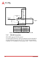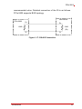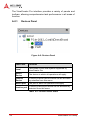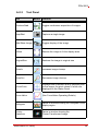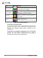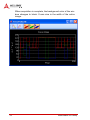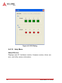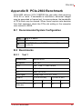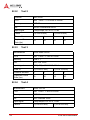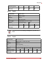
1
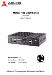
PCIe-2602 3G-SDI Audio/Video Capture Card User’s Manual Manual Rev.: 3.00 Revision Date: Aug. 23, 2013 Part No: 50-11251-1010 Advance Technologies; Automate the World. Revision History ii Revision Release Date Description of Change(s) 2.00 June 28, 2013 Initial release 3.00 Aug. 23, 2013 Revised specification PCIe-2602 Preface Copyright 2013 ADLINK Technology, Inc. This document contains proprietary information protected by copyright. All rights are reserved. No part of this manual may be reproduced by any mechanical, electronic, or other means in any form without prior written permission of the manufacturer. Disclaimer The information in this document is subject to change without prior notice in order to improve reliability, design, and function and does not represent a commitment on the part of the manufacturer. In no event will the manufacturer be liable for direct, indirect, special, incidental, or consequential damages arising out of the use or inability to use the product or documentation, even if advised of the possibility of such damages. Environmental Responsibility ADLINK is committed to fulfill its social responsibility to global environmental preservation through compliance with the European Union's Restriction of Hazardous Substances (RoHS) directive and Waste Electrical and Electronic Equipment (WEEE) directive. Environmental protection is a top priority for ADLINK. We have enforced measures to ensure that our products, manufacturing processes, components, and raw materials have as little impact on the environment as possible. When products are at their end of life, our customers are encouraged to dispose of them in accordance with the product disposal and/or recovery programs prescribed by their nation or company. Trademarks Product names mentioned herein are used for identification purposes only and may be trademarks and/or registered trademarks of their respective companies. Preface iii Conventions Take note of the following conventions used throughout this manual to make sure that users perform certain tasks and instructions properly. Additional information, aids, and tips that help users perform tasks. NOTE: CAUTION: WARNING: iv Information to prevent minor physical injury, component damage, data loss, and/or program corruption when trying to complete a task. Information to prevent serious physical injury, component damage, data loss, and/or program corruption when trying to complete a specific task. Preface PCIe-2602 Table of Contents Revision History...................................................................... ii Preface .................................................................................... iii List of Figures ....................................................................... vii List of Tables.......................................................................... ix 1 Introduction ........................................................................ 1 1.1 Overview.............................................................................. 1 1.2 Features............................................................................... 1 1.3 Applications ......................................................................... 1 1.4 1.5 Specifications....................................................................... 2 1.4.1 Software Support........................................................ 2 1.4.2 Video & Audio............................................................. 2 1.4.3 Power Consumption ................................................... 4 1.4.4 Electrical ..................................................................... 4 1.4.5 Physical ...................................................................... 6 Schematics, I/O and Indicators............................................ 6 1.5.1 SDI Connector ............................................................ 8 1.5.2 RS-485 Connector...................................................... 8 1.5.3 DI/O (Digital Input/Output) Connector ........................ 9 1.5.4 LED Indicators .......................................................... 13 1.5.5 Switch Settings ......................................................... 15 1.5.6 Digital I/O Connections............................................. 17 1.5.7 RS-485 Connection .................................................. 22 2 Getting Started ................................................................. 25 2.1 Unpacking Checklist .......................................................... 25 2.2 Installation.......................................................................... 25 Table of Contents v A Appendix: ViewCreator Pro Utility ...................................27 A.0.1 Devices Panel........................................................... 28 A.0.2 Tool Panel ................................................................ 29 A.0.3 Display Panel............................................................ 36 A.0.4 Status Panel ............................................................. 36 A.0.5 Display Menu ............................................................ 37 A.0.6 Color Format Menu................................................... 38 A.0.7 Audio Format Menu .................................................. 38 A.0.8 Image Size Menu...................................................... 39 A.0.9 Tool Menu................................................................. 39 A.0.10 Help Menu ................................................................ 40 B Appendix: PCIe-2602 Benchmark.....................................43 B.1 Recommended System Configuration ............................... 43 B.2 Benchmarks ....................................................................... 43 B.2.1 Test 1........................................................................ 43 B.2.2 Test 2........................................................................ 44 B.2.3 Test 3........................................................................ 44 B.2.4 Test 4........................................................................ 44 B.2.5 Test 5........................................................................ 45 B.2.6 Test 6........................................................................ 45 Important Safety Instructions............................................... 47 Getting Service ...................................................................... 49 vi Table of Contents PCIe-2602 List of Figures Figure 1-1: PCIe-2602 Schematic Diagram ....................................... 6 Figure 1-2: PCIe-2602 Board Layout ................................................. 7 Figure 1-3: I/O & Indicator Panel........................................................ 7 Figure 1-4: SDI Connector ................................................................. 8 Figure 1-5: RS-485 Connector ........................................................... 8 Figure 1-6: DI/O Connector................................................................ 9 Figure 1-7: D-sub Connector Cable ................................................. 11 Figure 1-8: D-sub Connector Cable Exterior Connector .................. 12 Figure 1-9: LED Indicators ............................................................... 13 Figure 1-10: Switch Locations............................................................ 15 Figure 1-11: PCIe-2602 Digital Input Functional Block Diagram........ 17 Figure 1-12: Sinking DI: Slider # of Switch 4 OFF ............................. 18 Figure 1-13: Sourcing DI: Slider # of Switch 4 is ON ......................... 19 Figure 1-14: PCIe -2602 Digital Output Functional Block Diagram.... 20 Figure 1-15: Sinking DO: Slider # of Switch 5 is OFF ........................ 21 Figure 1-16: Sourcing DO: Slider # of Switch 5 is ON ....................... 22 Figure 1-17: RS-485 Connection ....................................................... 23 Figure A-1: ViewCreator Pro Interface ............................................. 27 Figure A-2: Devices Panel................................................................ 28 Figure A-3: Status Panel .................................................................. 36 Figure A-4: SDI Display Menu .......................................................... 37 Figure A-5: DI/O Dialog .................................................................... 40 Figure A-6: About Device Dialog ...................................................... 41 List of Figures vii This page intentionally left blank. viii List of Figures PCIe-2602 List of Tables Table Table Table Table Table 1-1: 1-2: 1-3: 1-4: 1-5: Table Table Table Table Table Table Table Table Table Table Table Table Table 1-6: 1-7: 1-8: 1-9: 1-10: 1-11: A-1: A-2: A-3: A-4: A-5: A-6: A-7: List of Tables Board Layout Legend ...................................................... 7 SDI Connector Pin Assignment ....................................... 8 RS-485 Connector Pin Assignment ................................. 9 D I/O Connector Pin Assignments ................................. 10 D-sub Connector Cable Exterior Connector Pin Assignments ............................................................ 13 LEDs 0 and 2 Indicator Legend ..................................... 13 LEDs 1 and 3 Indicator Legend ..................................... 14 Switch Functions............................................................ 15 Card ID Switch Settings (S1) ......................................... 16 D I/O Switch Settings (S4) ............................................. 16 D I/O Switch Settings (S5) ............................................. 17 Devices Panel Items ...................................................... 28 Tool Panel Controls ....................................................... 30 FocusValue Tools .......................................................... 35 Status Panel Display Categories ................................... 36 SDI (BNC) Available Formats ........................................ 38 Available Color Formats ................................................ 38 Available Audio Formats................................................ 38 ix This page intentionally left blank. x List of Tables PCIe-2602 1 Introduction 1.1 Overview The PCIe-2602 3G-SDI Audio/Video Capture Card, based on the PCI Express® x4 interface, enables acquisition of 2 channels 3G-SDI, low latency, and raw video data signals up to 1920x1080P/60fps (frames per second). Thanks to 3G capability, ADLINK’s PCIe-2602 supports high accuracy color format, such as 12 bit 4:4:4 1080i/60fps or 10 bit 4:2:2 1080P/60fps, and when combined with a suitable 75Ω coaxial cable, 3G-SDI signals can be transmitted over 100 m, suiting the PCIe-2602 for medical imaging and intelligent video surveillance and analysis. The included ViewCreator Pro® utility enables setup, configuration, testing, and system debugging without requiring any software programming. As well, ADLINK's drivers are compatible with Microsoft® DirectShow, reducing engineering efforts and accelerating time to market. 1.2 Features X Support for 2-CH 3G-SDI video signal, up to 1920 x 1080P/60fps video stream X Low latency, uncompressed video streaming X High accuracy color format support, 12 bit 4:4:4 1080i/60fps or 10 bit 4:2:2 1080P/60fps X Cabling distances up to 100m (w/ compatible 75Ω coaxial cable) X Directshow support X RS-485 and Digital I/O provided X PCI Express x4 compliant signal X Connection Status LED 1.3 Applications The PCIe-2602, featuring 3G signal capture ability and support for highly accurate color formatting, is ideal for frame grab function in Introduction 1 a wide variety of applications, including medical imaging and intelligent video surveillance or analytics. The PCIe-2602 Function Library Reference can be downloaded from the product’s pages at http://www.adlinktech.com NOTE: 1.4 Specifications The PCIe-2602 provides 2 BNC connectors that support 2 channels of video and embedded audio, with maximum video data throughput of 2.97Gb/s, with 1.485G and 270M bps supported, and RS-485 and digital I/O simplify connection with other devices. 1.4.1 Software Support X OS supported: Win 7/XP/8, 32/64-bit X Software compatibility: Visual C++, C#, Visual Basic.Net, Borland C++ Builder NOTE: 1.4.2 Microsoft .NET Framework 3.5 must be installed if the OS is Windows 8, to ensure complete installation and proper utility function Video & Audio The PCIe-2602 supports the following video and audio formats. 2 Item Specification Color space Replicates video source Introduction PCIe-2602 Item Specification SD Interlace pattern 525i([email protected]/60Hz), 625i(720x576i@50Hz) HD interlace pattern 1080i50(1920x1080i@50Hz), 1080i60([email protected]/60Hz) HD progressive pattern 720p24(1280x720p@24Hz), 720p25(1280x720p@25Hz), 720p30(1280x720p@30Hz), 720p50(128x720p@50Hz), 720p60([email protected]/60Hz), 1080p24([email protected]/24Hz, 1080p25(1920x1080p@25Hz), 1080p30(1920x1080p@30Hz), 1080p50(1920x1080p@50Hz), 1080p60([email protected]/60Hz) 8/10 bit 4:4:4 1080p24, 1080p25, 1080p30, 720p24, 720p25, 720p30*, 720p50, 720p60, 1080i50, 1080i60 12 bit 4:4:4 1080p24, 1080p25, 1080p30, 1080i50, 1080i60 8/10 bit 4:2:2 1080p50, 1080p60, 1080p24, 1080p25, 1080p30, 720p24, 720p25, 720p30, 720p50, 720p60, 1080i50, 1080i60 12 bit 4:2:2 1080p24, 1080p25, 1080p30, 1080i50, 1080i60 8 bit 4:2:2 525i, 625i Video input resolution Supported video sampling Audio channel 2 channels/port Audio sample 16/20/24 bits (setting must follow audio source) word length Introduction 3 NOTE: 1.4.3 1.4.4 If the input source is 720p30, 8/10 bit 4:4:4, the PCIe-2602 can only capture the video signal without audio signal. In ViewCreator Pro, adjust Video Format and Color Format to display the image normally. Format in the API GetDetectedSensorFormat (UINT Number, int& Format) will return -1 when the input source is 720p30, 8/10 bit 4:4:4. Power Consumption Test Item Value DC 3.3V 1.5A DC 12V 1.2A Electrical The following specification includes values for SDI, PCI Express, and digital Input and Output. Parameter Min. Type Max. -- 2.2V -- Comment SDI Serial input common mode voltage PCI Express Differential Input High Threshold for REFCLK and PER Differential Input Low Threshold for REFCLK and PER +300mV Rt=100ohm, VCM=+1.2V -300mV High Differential Output for PET Low Differential Output for PET 4 -300mV +300mV Rt=100ohm, VCM=+1.25 V Introduction PCIe-2602 Parameter Min. Type Max. Input High Threshold for WAKE#, PERST# , +2.0V SMCLK and SMDAT +3.45V Input Low Threshold for WAKE#, PERST#, SMCLK and SMDAT +0.8V -0.3V Comment Digital Input Number of Channels 4 digital inputs Input Resistance 1 KΩ Input High Threshold 2V 12V Input Low Threshold 0V 0.8V Input power dissipation 0W 0.17W Input signal Frequency Test condition: Ta=25℃ 1kHz Test condition: Ta=25℃ 50mA Test condition: Ta=25℃ Digital Output Number of Channels 4 digital outputs Output sink current Output Type Open collect/TTL TTL mode Power on status Open collect mode High Z High State(+5V) Response Time Introduction 1kHz Test condition: Ta=25℃ 5 1.4.5 Physical Dimensions 149mm x 111.15mm Operating Temperature 0˚C to 60˚C Storage Temperature -20°C to 80°C Humidity 5%~95% (non-condensing) Safety Compliance CE & FCC 1.5 Schematics, I/O and Indicators All dimensions shown are in mm NOTE: 162.74 149 98.4 111.15 126.37 Figure 1-1: PCIe-2602 Schematic Diagram 6 Introduction PCIe-2602 A B C Figure 1-2: PCIe-2602 Board Layout A D I/O B SDI C RS-485 Table 1-1: Board Layout Legend I/O and indicator panel elements are labeled as follows Figure 1-3: I/O & Indicator Panel Introduction 7 1.5.1 SDI Connector 1 2 Figure 1-4: SDI Connector Pin Function Type 1 SDI signal Input 2 SDI signal GND Reference ground Table 1-2: SDI Connector Pin Assignment 1.5.2 RS-485 Connector The PCIe-2602 RS-485 connector is a DSUB-9 male configuration. 1 5 6 9 Figure 1-5: RS-485 Connector 8 Introduction PCIe-2602 Pin Function Type 1 RS485 Channel 1 data+ Dual direction 2 RS485 Channel 1 data- Dual direction 3 RS485 Channel 2 data+ Dual direction 4 RS485 Channel 2 data- Dual direction 5 Digital GND Reference ground 6 Digital GND Reference ground 7 Digital GND Reference ground 8 Digital GND Reference ground 9 Digital GND Reference ground Table 1-3: RS-485 Connector Pin Assignment 1.5.3 DI/O (Digital Input/Output) Connector The PCIe-2602 DI/O connector is a 16 pin-header configuration. 15 1 16 2 Figure 1-6: DI/O Connector Pin Function Type 1 DI3- Digital Input channel 3 invert pin 2 DI0+ Digital Input channel 0 non-invert pin 3 DI2- Digital Input channel 2 invert pin 4 DI1+ Digital Input channel 1 non-invert pin 5 DI1- Digital Input channel 1 invert pin Introduction 9 Pin Function Type 6 DI2+ Digital Input channel 2 non-invert pin 7 DI0- Digital Input channel 0 invert pin 8 DI3+ Digital Input channel 3 non-invert pin 9 DO0 Digital Output channel 0 10 GND Digital Ground 11 DO1 Digital Output channel 1 12 GND Digital Ground 13 DO2 Digital Output channel 2 14 Clamp Digital Output Darlington IC clamping voltage 15 DO3 Digital output channel 3 Table 1-4: D I/O Connector Pin Assignments 10 Introduction PCIe-2602 External access to the DI/O connector can be provided using ADLINK's separately available D-sub connector cable with external bracket (ADLINK part number: 30-25013-0000). Figure 1-7: D-sub Connector Cable Introduction 11 15 8 9 1 Figure 1-8: D-sub Connector Cable Exterior Connector 12 Pin Function Type 1 DI3- Input 9 DI0+ Input 2 DI2- Input 10 DI1+ Input 3 DI1- Input 11 DI2+ Input 4 DI0- Input 12 DI3+ Input 5 DO0 Output 13 GND DO Ground Introduction PCIe-2602 Pin Function Type 6 DO1 Output 14 GND DO Ground 7 DO2 Output 15 DO clamp DO Power 8 DO3 Output Table 1-5: D-sub Connector Cable Exterior Connector Pin Assignments 1.5.4 LED Indicators Four LED indicators on the I/O panel indicate SDI signal connection and status. Figure 1-9: LED Indicators LEDs 0 and 1 indicate status of vertical synchronization signals, while 2 and 3 confirm data verification, as follows. LED 0 LED 2 Description Blinking On The input signal is identified and channel 0 is functioning normally Off No input is detected or the input signal cannot be identified. The connection or cable should be checked, or the input signal format determined to be SDI. Off Table 1-6: LEDs 0 and 2 Indicator Legend Introduction 13 LED 1 LED 3 Description Blinking On The input signal is identified and channel 1 is functioning normally Off No input is detected or the input signal cannot be identified. The connection or cable should be checked, or the input signal format determined to be SDI. Off Table 1-7: LEDs 1 and 3 Indicator Legend NOTE: 14 If a signal is received but unidentified, please check the SDI signal format according to Section 1.4.2 Video & Audio. The PCIe-2602 may support resolutions not listed, please contact ADLINK FAE for support. Introduction PCIe-2602 1.5.5 Switch Settings Switches for digital I/O and card ID settings, allowing identification of individual cards in a multi-card system, are located as follows. S1 S4 S5 Figure 1-10: Switch Locations Switch Function S1 Card ID Settings S4-S5 Digital I/O Settings Table 1-8: Switch Functions Default setting for sliders S1, S4 and S5 is OFF NOTE: Introduction 15 Card ID Slider 1 Slider 2 Slider 3 Slider 4 15 on on on on 14 off on on on 13 on off on on 12 off off on on 11 on on off on 10 off on off on 9 on off off on 8 off off off on 7 on on on off 6 off on on off 5 on off on off 4 off off on off 3 on on off off 2 off on off off 1 on off off off 0 off off off off Table 1-9: Card ID Switch Settings (S1) DI Channel DI Status Slider Setting DI0 Pulled high to +5V 1 On DI0 Low 1 Off DI1 Pulled high to +5V 2 On DI1 Low 2 Off DI2 Pulled high to +5V 3 On DI2 Low 3 Off DI3 Pulled high to +5V 4 On DI3 Low 4 Off Table 1-10: D I/O Switch Settings (S4) 16 Introduction PCIe-2602 DI Channel DI Status Slider Setting DO0 Pulled high to +5V 1 On DO0 Low 1 Off DO1 Pulled high to +5V 2 On DO1 Low 2 Off DO2 Pulled high to +5V 3 On DO2 Low 3 Off DO3 Pulled high to +5V 4 On DO3 Low 4 Off Table 1-11: D I/O Switch Settings (S5) 1.5.6 Digital I/O Connections Function block diagrams and connection examples for digital I/O settings follow. Digital Input Figure 1-11: PCIe-2602 Digital Input Functional Block Diagram Introduction 17 In the following, varying situations are illustrated in which channel # of digital input is connected, where # is 0 to 3. PCIe-2602 +5V 330 +3.3V S4 DI IN# + (From Connector) DI#(To FPGA) VCC from user 1k DI IN# - (From Connector) API (DI Status) DO Status from User 1 High Z 0 Low DC DO from user Figure 1-12: Sinking DI: Slider # of Switch 4 OFF 18 Introduction PCIe-2602 PCIe-2602 +5V 330 +3.3V S4 DI IN# +(From Connector) DI#(To FPGA) 1k DI IN# - (From Connector) DO from user GND API (DI Status) DO Status from User 1 High Z 0 Low Figure 1-13: Sourcing DI: Slider # of Switch 4 is ON Introduction 19 Digital Output Figure 1-14: PCIe -2602 Digital Output Functional Block Diagram In the following, varying situations are illustrated in which channel # of digital output is connected, where # is 0 to 3. 20 Introduction PCIe-2602 PCIe-2602 Clamp +5V User VCC DC User Device Load Darlington Driver S5 User DI DO# (From FPGA) DO Out# (To connector) GND API (DO Output) DO Out# to Connector 1 Low(0V) 0 High Z Figure 1-15: Sinking DO: Slider # of Switch 5 is OFF Introduction 21 PCIe-2602 Clamp +5V 330 Darlington Driver S5 User DI DO# (From FPGA) DO Out# (To connector) User Device Load GND API(DO Output) DO Out# to Connector 1 Low (0V) 0 High (+5V) Figure 1-16: Sourcing DO: Slider # of Switch 5 is ON 1.5.7 RS-485 Connection PCIe-2602 supports RS-485 protocol To avoid signal reflections, each bus segment must be blanked at its physical beginning and end with the characteristic impedance. A resistor, Rt, is installed for this purpose, with – 130Ω ± 2% the 22 Introduction PCIe-2602 recommended value. Detailed connection of the Rt is as follows. PCIe-2602 supports BUS topology. User device PCIe-2602 D+ D+ 130ȍ 130ȍ (Rt) D- D- Figure 1-17: RS-485 Connection Introduction 23 This page intentionally left blank. 24 Introduction PCIe-2602 2 Getting Started 2.1 Unpacking Checklist Before unpacking, check the shipping carton for any damage. If the shipping carton and/or contents are damaged, inform your dealer immediately. Retain the shipping carton and packing materials for inspection. Obtain authorization from your dealer before returning any product to ADLINK. Ensure that the following items are included in the package. X PCIe-2602 unit X Quick Start Guidel OEM versions with non-standard configuration, functionality, or packaging may vary according to individual requirements. NOTE: 2.2 Installation The following describes installation of the PCIe-2602 module on the PCI express bus. 1. Remove the computer cover according to the computer manual.. NOTE: A vacant PCI express slot is required for installation of the PCIe-2602 module; if none is available, remove a PCI express board and note the slot number. 2. Remove the slot cover (if any). 3. Carefully position the PCIe-2602 in the selected PCI express slot. If installing in a tower computer, align the board with the board slots. 4. Press the board firmly but carefully into the connector. 5. Anchor the board with the screw. 6. Connect the SDI source and PCIe-2602 with the BNC coaxial cable. Getting Started 25 7. Power up the computer. The PCIe-2602 can be installed in a PCI Express x4, x8, or pcie PCIe x16 slot. NOTE: 26 Getting Started PCIe-2602 Appendix A ViewCreator Pro Utility The included ViewCreator Pro utility provides simple yet powerful setup, configuration, testing, and debugging of your vision system. NOTE: ViewCreator Pro is available for Windows XP/7/8 systems only, with recommended screen resolution exceeding 800x600. Microsoft .NET Framework 3.5 must be installed if the OS is Windows 8, to ensure complete installation and proper utility function ViewCreator Pro provides X 32/64-bit compatibility under Windows XP/Vista/7 DirectShow driver X Access to and configuration of PCIe-2602 cards X Video picture adjustment X Image file (BMP or JPG) viewing and saving X Access to general purpose I/O Figure A-1: ViewCreator Pro Interface ViewCreator Pro Utility 27 The ViewCreator Pro interface provides a variety of panels and toolbars, allowing comprehensive task performance in all areas of function. A.0.1 Devices Panel Figure A-2: Devices Panel Panel Item Function Local Lists cards on the local system supported by ViewCreator Pro Active Device The device to which all operations will apply Inactive Device Currently inactive devices which can be activated by selection from this menu Active port The port to which all operations will apply Inactive port Currently inactive port which can be activated by selection from this menu Table A-1: Devices Panel Items 28 ViewCreator Pro Utility PCIe-2602 A.0.2 Tool Panel Tool Button Function ContinueGrab Toggles continuous acquisition of images . Captures a single image SnapShot . Hide/Show Image Toggles display of the image . FitSize Resizes the image to fit the display area . Restores the image to original size OriginalSize . ZoomIn Increases image closeup . Decreases image closeup ZoomOut . FocusCross . Focus Value Displays blue crosshairs at any selected point on the image, the pixel values of which are displayed on the Status Panel (See FocusValue Operating Details) . Histogram Fourier Transform ViewCreator Pro Utility Opens a window showing the histogram of the . display region Opens a window showing the Fourier-Transformed image . 29 Tool HSI Conversion YCbCr Enable Image Flip Button Function Opens a window showing the HSI values along . the selected line on the image Transforms the image to YCbCr color space, . toggling YCbCr Enable/Y Enable (CbCr=128)/ CbCr Enable (Y=0)/YCbCr Disable Toggles No Flip/Flip X axis (horizontal)/Flip Y axis (vertical) . Record Toggles Record function (Function supports only 4:2:2 8-bit video input) . Table A-2: Tool Panel Controls FocusValue Operating Details A Focus Value window opens, displaying pixel values along a selected horizontal line of the image, which is displayed as red. Selecting the displayed image allows movement of the selected line. If acquisition is in progress, the background color of the window is gray. The chart updates immediately once an image is acquired. The x-axis region is determined by the number of horizontal pixels shown in the display panel. 30 ViewCreator Pro Utility PCIe-2602 ViewCreator Pro Utility 31 When acquisition is complete, the background color of the window changes to black. X-axis size is the width of the entire image. 32 ViewCreator Pro Utility PCIe-2602 If the image is chromatic, three curves, individually representing red, green, and blue are shown. ViewCreator Pro Utility 33 If the color format of captured image is YUV, three curves individually representing Y, U, and V are shown. 34 ViewCreator Pro Utility PCIe-2602 FocusValue Tools Tool Button Function Zoom In Increases closeup on the area in the FocusValue window bound by the green rectangle, which can be resized by dragging the side borders Differential Displays slope of the line for the area in the FocusValue window bound by the green rectangle, which can be resized by dragging the side borders Show/Hide Red Values Toggles display of red pixel values. Show/Hide Green Values Toggles display of green pixel values. Show/Hide Blue Values Toggles display of blue pixel values. Show/Hide Y Values Toggles display of Y pixel values. Show/Hide U Values Toggles display of U pixel values. Show/Hide V Values Toggles display of V pixel values. Table A-3: FocusValue Tools ViewCreator Pro Utility 35 A.0.3 Display Panel Captured images are displayed on this panel as shown. A.0.4 Status Panel Displays image acquisition, signal, and image statistics, as shown. Figure A-3: Status Panel Top Row (L to R) Selected port and channel Cursor position Pixel value Capture rate Display rate Total captured frames Display magnification (horizontal & vertical ratios) Bottom Row (L to R) Red component statistics Green component statistics Blue component statistics Signal detection status Table A-4: Status Panel Display Categories 36 ViewCreator Pro Utility PCIe-2602 A.0.5 Display Menu Allows selection of desired video format based on SDI(BNC). The SDI menu is shown open as an example. Figure A-4: SDI Display Menu Format Resolution 525i 29.97/30 fps 720 x 486 625i 25 fps 720 x 576 720p 24 fps 1280 x 720 720p 25 fps 1280 x 720 720p 30 fps 1280 x 720 720p 50 fps 1280 x 720 720p 59.94/60 fps 1280 x 720 ViewCreator Pro Utility 37 Format Resolution 1080i 25 fps 1920 x 1080 1080i 29.97/30 fps 1920 x 1080 1080p 23.98/24 fps 1920 x 1080 1080p 25 fps 1920 x 1080 1080p 30 fps 1920 x 1080 1080p 50 fps 1920 x 1080 1080p 59.97/60 fps 1920 x 1080 Table A-5: SDI (BNC) Available Formats A.0.6 Color Format Menu Sets the captured image to the selected color format. YCbCr 4:2:2 8bit (YUY2) YCbCr 4:4:4 8bit (YUV8) RGB 4:4:4 8bit (RGB24) YCbCr 4:2:2 10bit (YU10) YCbCr 4:4:4 10bit (YUV10) RGB 4:4:4 10bit (GBR30) YCbCr 4:2:2 12bit (YU12) YCbCr 4:4:4 12bit (YUV12) RGB 4:4:4 12bit (RGB36) Table A-6: Available Color Formats A.0.7 Audio Format Menu Sets the audio format, with available Sample Rates and Channels variable according to the input selected. Sampling Rate 48 kHz Sample Bits 16 bit 20 bit 24 bit Channels 2.0 (2) Table A-7: Available Audio Formats 38 ViewCreator Pro Utility PCIe-2602 A.0.8 Image Size Menu Top-down Enables top-down image display. Top-down function, when enabled, may improve capture efficency in computers experiencing low frame rate due to performance. Auto Detect Automatically detects image resolution A.0.9 Tool Menu DI/O Sets and retrieves digital input/output status, select digital output and digital input conditions. ViewCreator Pro Utility 39 Figure A-5: DI/O Dialog A.0.10 Help Menu About Device Displays card ID, hardware version, firmware version, driver version, and utility version information. 40 ViewCreator Pro Utility PCIe-2602 Figure A-6: About Device Dialog ViewCreator Pro Utility 41 This page intentionally left blank. 42 ViewCreator Pro Utility PCIe-2602 Appendix B PCIe-2602 Benchmark PCIe-2602 delivers 2-CH 1080P/60 fps raw video data requiring PCIe X4 or more. If bandwidth is insufficient, abnormal images may be generated or frames lost. In some systems, the bandwidth of PCIe slots may be shared. When frame capture rate deviates from that expected, check the PCIe slot setting in the computer user manual or BIOS. B.1 Recommended System Configuration CPU Intel i5 or above RAM 4GB OS Win XP/7/8 (Microsoft .NET Framework 3.5 is needed for Win 8) B.2 Benchmarks B.2.1 Test 1 Motherboard NuPRO-E330 Backplane EBP-9E2 CPU Intel® Core™ i7 860 2.8GHz Memory 1GB X 2 OS Win7 Pro 32 bit Input signal 1080p 60fps,YUV 4:2:2, 10 bit Card ID 0 (PCIe x16 slot) 1 (PCIe x 4 slot) Channel number 0 1 0 1 Captured Frame Rate (fps) 60 60 60 60 PCIe-2602 Benchmark 43 B.2.2 Platform MXC-6300 CPU Intel® Core™ i7 3610QE 2.30GHz Memory 8GB X2 OS WinXP Professional 32 bit Input signal 1080p 60fps,YUV 4:2:2, 10 bit Card# 0 (PCIe x8 slot) 1 (PCIe x8 slot) Channel# 0 1 0 1 Captured Frame Rate (fps) 60 60 60 60 B.2.3 Test 3 Motherboard GIGA-X58A-UD3R CPU Intel® Core™ i7 920 2.67GHz Memory 4GB X 1 OS Win7 Pro 32 bit Input signal 1080p 60fps,YUV 4:2:2, 10 bit Card ID 0 (PCIe x16 slot) 1 (PCIe x16 slot) Channel Number 0 1 0 1 Captured Frame Rate (fps) 60 60 60 60 B.2.4 44 Test 2 Test 4 Motherboard ASUS P6TSE CPU Intel® Core™ i7 920 2.67GHz Memory 2GB X 1 OS Win7 Ultimate 32 bit Input signal 1080p 60fps,YUV 4:2:2, 10 bit Card ID 0 (PCIe x16 slot) 1 (PCIe x16 slot) PCIe-2602 Benchmark PCIe-2602 Channel Number 0 1 0 1 Captured Frame Rate (fps) 60 60 60 60 B.2.5 Test 5 Motherboard ASUS P8P67 CPU Intel® i5 2400 Memory 2GB X 1 OS Win7 Pro 32 bit Input signal 1080p 60fps,YUV 4:2:2, 10 bit Card ID 0 (PCIe x16 slot) NA Channel Number 0 1 NA NA Captured Frame Rate (fps) 60 60 NA NA The PCIe PCIe x16 slot setting is changed to “X4 mode” via BIOS. NOTE: B.2.6 Test 6 Motherboard GIGA-X58A-UD7 CPU Intel® Core™ i7 950 3.07 GHz Memory 2GB X 2 OS Win7 Pro 32 bit Input signal 1080p 60fps,YUV 4:2:2, 10 bit Card ID 0 (PCIe x16 slot) 1 (PCIe x16 slot) 2 (PCIe x16 slot) Channel Number 0 1 0 1 0 1 Captured Frame Rate (fps) 60 60 60 60 60 60 PCIe-2602 Benchmark 45 This page intentionally left blank. 46 PCIe-2602 Benchmark PCIe-2602 Important Safety Instructions For user safety, please read and follow all instructions, WARNINGS, CAUTIONS, and NOTES marked in this manual and on the associated equipment before handling/operating the equipment. X Read these safety instructions carefully. X Keep this user’s manual for future reference. X Read the specifications section of this manual for detailed information on the operating environment of this equipment. X When installing/mounting or uninstalling/removing equipment: Z X Turn off power and unplug any power cords/cables. To avoid electrical shock and/or damage to equipment: Z Keep equipment away from water or liquid sources; Z Keep equipment away from high heat or high humidity; Z Keep equipment properly ventilated (do not block or cover ventilation openings); Z Make sure to use recommended voltage and power source settings; Z Always install and operate equipment near an easily accessible electrical socket-outlet; Z Secure the power cord (do not place any object on/over the power cord); Z Only install/attach and operate equipment on stable surfaces and/or recommended mountings; and, Z If the equipment will not be used for long periods of time, turn off and unplug the equipment from its power source. Important Safety Instructions 47 X Never attempt to fix the equipment. Equipment should only be serviced by qualified personnel. A Lithium-type battery may be provided for uninterrupted, backup or emergency power. Risk of explosion if battery is replaced with one of an incorrect type. Dispose of used batteries appropriately. WARNING: X 48 Equipment must be serviced by authorized technicians when: Z The power cord or plug is damaged; Z Liquid has penetrated the equipment; Z It has been exposed to high humidity/moisture; Z It is not functioning or does not function according to the user’s manual; Z It has been dropped and/or damaged; and/or, Z It has an obvious sign of breakage. Important Safety Instructions PCIe-2602 Getting Service Contact us should you require any service or assistance. ADLINK Technology, Inc. Address: 9F, No.166 Jian Yi Road, Zhonghe District New Taipei City 235, Taiwan ᄅؑקխࡉ৬ԫሁ 166 ᇆ 9 ᑔ Tel: +886-2-8226-5877 Fax: +886-2-8226-5717 Email: [email protected] Ampro ADLINK Technology, Inc. Address: 5215 Hellyer Avenue, #110, San Jose, CA 95138, USA Tel: +1-408-360-0200 Toll Free: +1-800-966-5200 (USA only) Fax: +1-408-360-0222 Email: [email protected] ADLINK Technology (China) Co., Ltd. Address: Ϟ⍋Ꮦ⌺ϰᮄऎᓴ∳催⾥ᡔುऎ㢇䏃 300 ো(201203) 300 Fang Chun Rd., Zhangjiang Hi-Tech Park, Pudong New Area, Shanghai, 201203 China Tel: +86-21-5132-8988 Fax: +86-21-5132-3588 Email: [email protected] ADLINK Technology Beijing Address: ࣫ҀᏖ⍋⎔ऎϞഄϰ䏃 1 োⲜ߯ࡼॺ E ᑻ 801 ᅸ(100085) Rm. 801, Power Creative E, No. 1, Shang Di East Rd., Beijing, 100085 China Tel: +86-10-5885-8666 Fax: +86-10-5885-8626 Email: [email protected] ADLINK Technology Shenzhen Address: ⏅ഇᏖफቅऎ⾥ᡔುफऎ催ᮄफϗ䘧᭄ᄫᡔᴃು A1 ᷟ 2 ὐ C ऎ (518057) 2F, C Block, Bldg. A1, Cyber-Tech Zone, Gao Xin Ave. Sec. 7, High-Tech Industrial Park S., Shenzhen, 518054 China Tel: +86-755-2643-4858 Fax: +86-755-2664-6353 Email: [email protected] LiPPERT ADLINK Technology GmbH Address: Hans-Thoma-Strasse 11, D-68163, Mannheim, Germany Tel: +49-621-43214-0 Fax: +49-621 43214-30 Email: [email protected] Getting Service 49 ADLINK Technology, Inc. (French Liaison Office) Address: 15 rue Emile Baudot, 91300 Massy CEDEX, France Tel: +33 (0) 1 60 12 35 66 Fax: +33 (0) 1 60 12 35 66 Email: [email protected] ADLINK Technology Japan Corporation Address: ͱ101-0045 ᵅҀ䛑गҷ⬄ऎ⼲⬄䤯 ⬎ފ3-7-4 ⼲⬄ 374 ɛɳ 4F KANDA374 Bldg. 4F, 3-7-4 Kanda Kajicho, Chiyoda-ku, Tokyo 101-0045, Japan Tel: +81-3-4455-3722 Fax: +81-3-5209-6013 Email: [email protected] ADLINK Technology, Inc. (Korean Liaison Office) Address: 昢殾柢 昢爎割 昢爎壟 1675-12 微汾瘶捒娯 8 猻 8F Mointer B/D,1675-12, Seocho-Dong, Seocho-Gu, Seoul 137-070, Korea Tel: +82-2-2057-0565 Fax: +82-2-2057-0563 Email: [email protected] ADLINK Technology Singapore Pte. Ltd. Address: 84 Genting Lane #07-02A, Cityneon Design Centre, Singapore 349584 Tel: +65-6844-2261 Fax: +65-6844-2263 Email: [email protected] ADLINK Technology Singapore Pte. Ltd. (Indian Liaison Office) Address: 1st Floor, #50-56 (Between 16th/17th Cross) Margosa Plaza, Margosa Main Road, Malleswaram, Bangalore-560055, India Tel: +91-80-65605817, +91-80-42246107 Fax: +91-80-23464606 Email: [email protected] ADLINK Technology, Inc. (Israeli Liaison Office) Address: 6 Hasadna St., Kfar Saba 44424, Israel Tel: +972-9-7446541 Fax: +972-9-7446542 Email: [email protected] 50 Getting Service