1
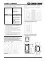
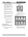
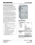
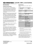
infiNET™ DIMMERS
Introduction
Features and Functions
The CLW-DIM1RF (-DIM1RF) and CLW-DIM4RF
(-DIM4RF) are stand-alone wall box dimmers that can
also act as wireless infiNET™ devices that report to a
Crestron® control processor through an infiNET gateway
such as the Crestron C2N-MNETGW. The -DIM1RF and
-DIM4RF have three preset lighting levels that can be
adjusted. For more information, refer to the latest version
of the infiNET Dimmers Operations Guide (Doc. 6396)
which is available from the Crestron website
(www.crestron.com/manuals).
These dimmers are part of Crestron’s line of lighting
products using infiNET mesh network technology.
infiNET technology is “Wi-Fi” friendly and provides fault
tolerance and increased effective signal strength as
network devices are added.
Up to 30 infiNET devices (including C2N-MNETRPT
infiNET Repeaters) can communicate with one
C2N-MNETGW Gateway. If more devices are needed,
more C2N-MNETGW gateways may be added to a
Cresnet® network.
The infiNET dimmers operate on the 2.4 GHz “ISM
band” (2400 MHz to 2483.6 MHz) at 10 mW. The output
power of these devices allow RF signals to travel
approximately 150 feet indoors and 250 feet outdoors
(subject to site-specific conditions) without the use of
repeaters or other infiNET devices. The range is
dependent on construction of the building, obstructions,
and RF interference from other devices. The location of
the dimmer is an important factor in determining RF
performance. Adding more infiNET devices or repeaters
to the network effectively increases the range, strength,
and reliability of the network.
The -DIM1RF and -DIM4RF feature a three-position
mode selection switch. For more information, refer to the
latest version of the infiNET Dimmers Operations Guide
(Doc. 6396) which is available from the Crestron website.
In the absence of control system communications, the
dimmer can still be used to control the attached load.
The CLW-DIMS1RF (-DIMS1RF) and CLW-DIMS4RF
(-DIMS4RF) are similar to the -DIM1RF and -DIM4RF
(respectively) with the added capability of working with
one or more slave units (CLW-SLVD1RF) in a multidimmer / single circuit application.
The CLW-SLVD1RF (-SLVD1RF) is a slave unit that
when used in conjunction with the -DIMS1RF or
-DIMS4RF acts as an additional dimmer control point in a
multi-dimmer / single circuit application. It does not
Crestron Electronics, Inc.
15 Volvo Drive Rockleigh, NJ 07647
Tel: 888.CRESTRON
Fax: 201.767.7576
www.crestron.com
connect to a Cresnet system and cannot be used without a
-DIMS1RF or -DIMS4RF. The -SLVD1RF does not have
a mode selection switch. It will emulate the RUN mode of
the -DIMS1RF (even if connected to a -DIMS4RF) unless
the mode selection switch of the master is set to “OFF”.
For more information, refer to the latest version of the
infiNET Dimmers Operations Guide (Doc. 6396) which is
available from the Crestron website.
These dimmers are available in a variety of colors and
textures. The table below shows the availability.
Available Colors/Textures
COLOR/
TEXTURE
MODEL NUMBER
SUFFIX
MATCHING LUTRON
FACEPLATE
White
W
Smooth White
W-S
Not Applicable
CW-1-WH
Almond
A
CW-1-LA
Smooth Almond
A-S
CW-1-LA
Black
B
Not Applicable
Smooth Black
B-S
CW-1-BL
Specifications
Following are specifications for the -DIM1RF, -DIM4RF,
-DIMS1RF, -DIMS4RF, and -SLVD1RF.
CLW-DIM1RF/-DIM4RF, CLW-DIMS1RF/-DIMS4RF, &
CLW-SLVD1RF Specifications
SPECIFICATION
DETAILS
Power Requirements
Line Power, 120 VAC, 60 Hz
Operating Frequency
2400 MHz to 2483.6 MHz
(802.15.4 compliant)
RF Output Power
10 mW
Operating Ranges¹
Typical Distance
Indoors
(without repeater)
Typical Distance
Outdoors
150 ft
250 ft
(subject to site-specific
conditions)
Default MNET ID
-DIM1RF/-DIM4RF: 01/01
-DIMS1RF/-DIMS4RF: 01/01
Switch Type
Dimmer
Load Type
Incandescent, TungstenHalogen, Magnetic Low Voltage
2-Series Control System
2,3
Update File
Version 3.154 or later
Load Ratings
4
Incandescent/TungstenHalogen
-DIM1RF/-DIM4RF: 1000W
-DIMS1RF/-DIMS4RF: 1000W
-SLVD1RF: N/A
(continued on following page)
Installation Guide – DOC. 6292C
(2011321)
03.09
Specifications subject to
change without notice.
infiNET™ DIMMERS
CLW-DIM1RF/-DIM4RF, CLW-DIMS1RF/-DIMS4RF, &
CLW-SLVD1RF Specifications (continued)
SPECIFICATION
DETAILS
Load Ratings (continued)
Magnetic Low Voltage
5
4
Line voltage connections are made at the rear of the
dimmer.
CLW-DIM1RF/-DIMS1RF (L) and CLW-SLVD1RF (R)
shown in white
-DIM1RF/-DIM4RF:
1000VA/750W
-DIMS1RF/-DIMS4RF:
1000VA/750W
-SLVD1RF: N/A
Operating Temperature
and Humidity
32°F to 104°F (0°C to 40°C)
10 to 90% Relative Humidity
(Non-Condensing)
Dimensions and Weight
-DIM1RF/-DIM4RF and
-DIMS1RF/-DIMS4RF:
Height: 4.13 in (10.48 cm)
Width: 2.38 in (6.03 cm)
Depth: 1.88 in (4.77 cm)
Weight: 4.9 oz (0.67 kg)
-SLVD1RF:
Height: 4.13 in (10.48 cm)
Width: 1.75 in (4.45 cm)
Depth: 1.88 in (4.77 cm)
Weight: 3.6 oz (0.50 kg)
1.
The range is dependent on its placement and the building in which
it is used. The construction of the building, obstructions, and RF
interference from other devices are factors determining the
effective range of the unit.
2.
The latest software versions can be obtained from the Crestron
website. Refer to the NOTE following these footnotes.
3.
Crestron 2-Series control systems include the AV2 and PRO2.
Consult the latest Crestron Product Catalog for a complete list of
2-Series control systems.
4.
Refer to Derating Charts for Multigang Installations on page 4.
5.
VA ratings are for input power to the transformer. If you do not
know the input power requirement of the transformer, use the
bulb’s wattage rating to determine proper rating.
NOTE: Crestron software and any files on the website
are for Authorized Crestron dealers and Crestron
Authorized Independent Programmers (CAIP) only. New
users may be required to register to obtain access to
certain areas of the site (including the FTP site).
Physical Description
The -DIM1RF and -DIMS1RF contain one rocker button,
a light emitting diode (LED) with software-adjustable
brightness, and a three-position slider-switch, shown in
the next column and on the following page.
CLW-DIM4RF/-DIMS4RF shown in white
Physical view of CLW-DIM1RF/-DIMS1RF
(clockwise from top; Top, Side, and Front)
1.75 in
(4.45 cm)
2.38 in
(6.03 cm)
3.81 in
(9.68 cm)
The -DIM4RF and -DIMS4RF contain four pushbuttons,
a light emitting diode (LED) with software-adjustable
brightness, and a three-position slider-switch, shown in
the next column and on the following page.
The -SLVD1RF is similar to the -DIM1RF and
-DIMS1RF but does not have the slider-switch. The
brightness of the LED on the -SLVD1RF is not
programmable.
1.88 in
(4.77 cm)
3.28 in
(8.32 cm)
RUN
SET
2.70 in
(6.86 cm)
4.13 in
(10.48 cm)
OFF
2 • infiNET™ Wall Box Dimmer : CLW-DIM1/4RF, DIMS1/4RF, & SLVD1RF
1.50 in
(3.81 cm)
Installation Guide – DOC. 6292C
infiNET™ DIMMERS
Physical view of CLW-DIM4RF/-DIMS4RF
(clockwise from top; Top, Side, and Front)
FCC ID: EROCWD1011
1.75 in
(4.45 cm)
Compliance Statement (Part 15.19 )
This device complies with Part 15 of the FCC Rules.
Operation is subject to the following two conditions:
2.38 in
(6.03 cm)
1.88 in
(4.77 cm)
RUN
SET
2.70 in
(6.86 cm)
4.13 in
(10.48 cm)
OFF
1.50 in
(3.81 cm)
Physical view of CLW-SLVD1RF (clockwise from top; Top,
Side, and Front)
This device must accept any interference received,
including interference that may cause undesired
operation.
RF Exposure (OET Bulletin 65)
To comply with FCC's RF exposure limits for general
population / uncontrolled exposure, this transmitter must
be installed to provide a separation distance of at least
20 cm from all persons and must not be co-located or
operating in conjunction with any other antenna or
transmitter.
Industry Canada Statement
The term "IC" before the certification/registration number
only signifies that the Industry Canada technical
specifications were met.
IC: 5683A-CWD1011
Read before installation.
3.81 in
(9.68 cm)
3.28 in
(8.32 cm)
2.
Important Notes
1.88 in
(4.77 cm)
1.75 in
(4.45 cm)
This device may not cause harmful interference, and
Warning (Part 15.21)
Changes or modifications not expressly approved by the
party responsible for compliance could void the user’s
authority to operate the equipment.
3.81 in
(9.68 cm)
3.28 in
(8.32 cm)
1.
•
Codes: Install in accordance with all local and
national electrical codes.
•
CAUTION: TO REDUCE THE RISK OF
OVERHEATING AND POSSIBLE DAMAGE
TO OTHER EQUIPMENT, DO NOT INSTALL
TO CONTROL A RECEPTACLE OR A
MOTOR OPERATED APPLIANCE (i.e. BATH
FAN).
2.70 in
(6.86 cm)
4.13 in
(10.48 cm)
1.50 in
(3.81 cm)
•
Wiring: Use copper wire only. For supply
connections, use wires rated for at least 75°C.
•
Lamp Type: The -DIM1RF, -DIM4RF,
-DIMS1RF, -DIMS4RF, and -SLVD1RF are
designed for use with permanently installed
incandescent, magnetic low voltage, or tungstenhalogen only.
•
Temperature: The -DIM1RF, -DIM4RF,
-DIMS1RF, -DIMS4RF, and -SLVD1RF are
designed for use where temperatures are between
32° to 104°F (0° to 40°C).
These devices mount in a standard wallbox and are
covered using a decorative faceplate (not included).
Industry Compliance
This product is Listed to applicable UL Standards and
requirements by Underwriters Laboratories Inc.
E239011
Installation Guide – DOC. 6292C
infiNET™ Wall Box Dimmer: CLW-DIM1/4RF, DIMS1/4RF, & SLVD1RF • 3
infiNET™ DIMMERS
•
•
Inner Sections of Multiganged Switches
(CLW-DIM4RF shown)
Wallboxes: Devices mount in standard
wallboxes. For easy installation, Crestron
recommends using 3 ½” deep wallboxes. Several
devices can be installed in one wall box
(multigang). This requires the removal of side
sections (refer to diagram on page 4) and the
derating of the dimming device. For a smooth
appearance, one-piece multigang faceplates (not
supplied) can be installed.
REMOVE INNER SECTIONS
Other Switch Devices: Mechanical 3- or 4-way
switches will not work with the - DIM1RF,
-DIM4RF, -DIMS1RF, -DIMS4RF, and
-SLVD1RF.
•
Spacing: If mounting one device above another,
leave at least 4 ½” vertical space between them.
•
Low Voltage Applications: Use with core and
coil (magnetic) low voltage transformers only.
Do not use any solid-state electronic low voltage
transformers.
Operation of a low voltage circuit with all lamps
inoperative or removed may result in current
flow in excess of normal levels. To avoid
transformer overheating and premature
transformer failure, Crestron recommends the
following:
¾
Do not operate low voltage circuits
without operative lamps in place.
¾
Replace burned-out lamps as quickly as
possible.
¾
Use transformers that incorporate
thermal protection or fuse transformer
primary windings to prevent
transformer failure due to overcurrent.
RUN
1.
When combining controls in a wallbox, remove
inner side sections prior to wiring as shown in
the following diagram.
OFF
RUN
SET
OFF
DO NOT REMOVE OUTER SECTIONS
The load capacity must also be derated. The
following charts provide derating information for
various applications.
Derating Information for Incandescent and TungstenHalogen Applications
Part
Number
No Side
Removed
One Side
Removed
Two Sides
Removed
-DIM1RF/
-DIM4RF
1000W
700W
550W
-DIMS1RF/
-DIMS4RF
1000W
700W
550W
-SLVD1RF
No Derating Necessary
Derating Information for Magnetic Low Voltage Applications*
Multigang Installations
In multigang installations, several controls are grouped
horizontally in one wallbox. For a smooth appearance,
one-piece multigang faceplates (not supplied) can be
installed.
SET
Part
Number
No Side
Removed
One Side
Removed
Two Sides
Removed
-DIM1RF/
-DIM4RF
1000VA/
750W
700VA/500W
550VA/
400W
-DIMS1RF/
-DIMS4RF
1000VA/
750W
700VA/500W
550VA/
400W
-SLVD1RF
*
No Derating Necessary
VA ratings are for input power to the transformer. If you do not
know the input power requirement of the transformer, use the bulb’s
wattage rating to determine proper rating.
2.
To remove a side section, bend the side section
back and forth with a pair of pliers until the
section breaks off from the mounting plate. Use a
file or sandpaper to remove any excess metal.
4 • infiNET™ Wall Box Dimmer : CLW-DIM1/4RF, DIMS1/4RF, & SLVD1RF
Installation Guide – DOC. 6292C
infiNET™ DIMMERS
3.
Push all power wires back into the wallbox and
fasten the device to the wallbox with the
provided screws.
4.
Attach decorative faceplate.
5.
Restore power at the circuit breaker.
Installation
WARNING: Turn off power at the circuit breaker.
Installing with power on can result in serious personal
injury and damage to the device.
NOTE: The -DIM1RF, -DIM4RF, -DIMS1RF,
-DIMS4RF, and -SLVD1RF require a neutral wire in the
wallbox for operation. If no neutral is present, contact a
licensed electrician for installation or refer to the
alternative wiring diagrams described in “Appendix:
Wiring Diagrams” on page 9.
NOTE: The -DIMS1RF and -DIMS4RF must be
installed in the same wallbox that contains the
connections to the load.
NOTE: New installations should be checked for short
circuits prior to installing an infiNET dimmer. With
power off, close the circuit and restore power. If the lights
do not work or a breaker trips, check and correct the
wiring or fixture (if necessary). Install the dimmer only
when the short is no longer present. The warranty is
void if the dimmer is installed and operated with a
shorted load.
Wiring a -DIMSXRF with One or More
-SLVD1RFs
NOTE: The -DIMS1RF and -DIMS4RF must be installed
in the same wallbox that contains the connections to the
load.
The following describes installation of a -DIMSXRF
master with a -SLVD1RF slave.
1.
Turn power off at the circuit breaker.
2.
Wire the dimmers as shown in Figure 4 on
page 10.
NOTE: Do not connect the BLUE (Slave) wire
to the Black (Hot) or RED (Load) wires.
NOTE: The RED (Load) and BLACK (Hot)
wires are #14 AWG. The BLUE (Slave) and
WHITE (Neutral) wires are #18 AWG. The
GREEN (Ground) wire is #16 AWG.
When installing a -DIMXRF or a -DIMSXRF without a
slave, follow the instructions in “Wiring a -DIM(S)XRF
(No Slaves)” below. If wiring a -DIMSXRF with a
-SLVD1RF, refer to “Wiring a -DIMSXRF with One or
More -SLVD1RFs” in the next column.
NOTE: If a -DIMS1RF or -DIMS4RF is
installed without a -SLVD1RF, the BLUE lead
(Slave) should be capped.
NOTE: The WHITE (Neutral) connection on
the -SLVD1RF is optional and is only required
for operation of the LED. If the neutral is not
available, the white lead should be capped off.
Wiring a -DIM(S)XRF (No Slaves)
The following describes the installation of a stand-alone
-DIM1RF, -DIM4RF, -DIMS1RF or -DIMS4RF.
1.
Turn power off at the circuit breaker.
2.
Wire the dimmer as shown in Figure 1 on
page 9.
NOTE: The RED (Load) and BLACK (Hot)
wires are #14 AWG. The BLUE (Slave) and
WHITE (Neutral) wires are #18 AWG. The
GREEN (Ground) wire is #16 AWG.
NOTE: Since the -DIMS1RF or -DIMS4RF is
installed without a -SLVD1RF, the BLUE lead
(Slave) should be capped.
Alternative Wiring
For situations where a neutral is not present or
other scenarios that may be encountered during
installation, refer to the “Master-Slave
Installations” section of “Appendix: Wiring
Diagrams” on page 10.
3.
Push all power wires back into the wallbox and
fasten the devices to their respective wallboxes
with the provided screws.
4.
Attach decorative faceplates.
5.
Restore power at the circuit breaker.
Alternative Wiring
For situations where a neutral is not present or
other scenarios that may be encountered during
installation, refer to the “Stand-Alone
Installations” section of “Appendix: Wiring
Diagrams” on page 9.
Installation Guide – DOC. 6292C
infiNET™ Wall Box Dimmer: CLW-DIM1/4RF, DIMS1/4RF, & SLVD1RF • 5
infiNET™ DIMMERS
Testing a -SLVD1RF
Testing
NOTE: The device may be warm to the touch during
operation. This is normal.
Test the installation by setting the dimmer’s mode
selection switch (shown in the following diagrams) to the
“RUN” position and perform either of the following steps
(depending on the dimmer model).
Parts of CLW-DIM1RF and -DIMS1RF
SET
infiNET Network
Before an infiNET dimmer can be used in a controlled
lighting system, it must first be acquired to a
C2N-MNETGW gateway that is connected to a Cresnet
network.
Button
RUN
Tap the top of the button to turn on the load. Tap the
bottom of the button to turn off the load. It will emulate
the RUN mode of the -DIMS1RF (even if connected to a
-DIMS4RF) unless the mode selection switch of the
master is set to “OFF”. For more information, refer to the
latest version of the infiNET Dimmers Operations Guide
(Doc. 6396) which is available from the Crestron website.
NOTE: The -DIM1RF, -DIM4RF, -DIMS1RF, and
-DIMS4RF can also work as stand-alone wall box
dimmers without being acquired by a C2N-MNETGW.
OFF
Mode Selection Switch
NOTE: A dimmer can be acquired to only one gateway.
To acquire a -DIM1RF/-DIM4RF/-DIMS1RF/-DIMS4RF
to a C2N-MNETGW, perform the following:
Parts of CLW-DIM4RF, -DIMS4RF
1.
Button 1
Button 2
Button 3
Button 4
RUN
SET
NOTE: In an environment where multiple
gateways are installed, only one gateway should
be in the Acquire mode at a time.
OFF
Mode Selection Switch
Testing a -DIM1RF or-DIMS1RF
With the mode selection switch in the “RUN” position,
tap the top of the button to turn on the load. Tap the
bottom of the button to turn off the load.
Put the C2N-MNETGW in the Acquire mode,
from the unit itself or from Crestron Toolbox™,
as described in the latest revision of the
C2N-MNETGW Operations Guide (Doc. 6317)
which is available from the Crestron website or
the Crestron Toolbox help file.
2.
Place the -DIM1RF/-DIM4RF/-DIMS1RF/
-DIMS4RF into the Acquire mode by doing the
following:
a.
Move the mode selection switch
(located under the LED) to the “OFF”
position.
b.
Press and hold the top or bottom of the
button on the -DIM1RF/-DIMS1RF or
any button on the -DIM4RF/
-DIMS4RF.
With the mode selection switch in the “RUN” position,
tap the Button 1 to turn on the load. Tap Button 1 again to
turn off the load.
c.
While holding the button, slide the
mode selection switch to the “RUN”
position.
For detailed operating instructions, refer to the latest
revision of the infiNET Dimmers Operations Guide (Doc.
6396) which is available from the Crestron website.
d.
Hold the button for approximately five
seconds until the LED flashes HIGH
once. Immediately release the button
after the LED blinks to start the
switch’s Acquire mode.
For detailed operating instructions, refer to the latest
revision of the infiNET Dimmers Operations Guide (Doc.
6396) which is available from the Crestron website.
Testing a -DIM4RF or -DIMS4RF
6 • infiNET™ Wall Box Dimmer : CLW-DIM1/4RF, DIMS1/4RF, & SLVD1RF
Installation Guide – DOC. 6292C
infiNET™ DIMMERS
NOTE: Holding the button for a significant
time after the first flash may enter other modes.
If this is not desired, return the mode selection
switch to the “OFF” position without releasing
the button and repeat step 2.
After approximately ten seconds, the LED will
start to blink slowly and the dimmer will attempt
to acquire with a C2N-MNETGW that is in the
Acquire mode. The device is acquired when the
LED stops blinking and lights at the LOW
setting. After being acquired, the device will exit
the Acquire mode.
The dimmer will be acquired on the
C2N-MNETGW with an MNET ID value of 01.
If the dimmer was previously acquired on
another infiNET network, the dimmer will be
acquired on the C2N-MNETGW with its
previous MNET ID.
3.
Take the C2N-MNETGW out of the Acquire
mode once all devices have been acquired. Refer
to the latest revision of the C2N-MNETGW
Operations Guide (Doc. 6317), which is
available from the Crestron website.
For more information, refer to the latest version of the
infiNET Dimmers Operations Guide (Doc. 6396) which is
available from the Crestron website.
Problem Solving
Troubleshooting
The table after this paragraph provides corrective action
for possible trouble situations. If further assistance is
required, please contact a Crestron customer service
representative.
infiNET Dimmer Troubleshooting
TROUBLE
Dimmer
does not
function.
POSSIBLE
CAUSE(S)
CORRECTIVE ACTION
Dimmer is
not
receiving
line power.
Verify that the dimmer is
properly connected to power
line and that the circuit
breaker is closed.
Load is not
connected.
Verify that load is operational
and that the mode selection
switch is in the RUN
position.
If the dimmer does not function after performing the
above corrective actions, restore the dimmer’s default
settings by moving the mode selection switch to the
“RUN” position. While holding the pushbutton (hold
“UP” on the -DIM1RF and -DIMS1RF, or hold Button 1
on the -DIM4RF or -DIMS4RF), move the mode
selection switch to the “SET” position and back to the
“RUN” position. Release the pushbutton. The LED will
flash once to confirm that the default values have been
restored.
Further Inquiries
If you cannot locate specific information or have
questions after reviewing this guide, please take
advantage of Crestron's award winning customer service
team by calling the Crestron corporate headquarters at
1-888-CRESTRON [1-888-273-7876].
You can also log onto the online help section of the
Crestron website (www.crestron.com/onlinehelp) to ask
questions about Crestron products. First-time users will
need to establish a user account to fully benefit from all
available features.
Future Updates
As Crestron improves functions, adds new features, and
extends the capabilities of the device, additional
information may be made available as manual updates.
These updates are solely electronic and serve as
intermediary supplements prior to the release of a
complete technical documentation revision.
Check the Crestron website periodically for manual
update availability and its relevance. Updates are
identified as an “Addendum” in the Download column.
Installation Guide – DOC. 6292C
infiNET™ Wall Box Dimmer: CLW-DIM1/4RF, DIMS1/4RF, & SLVD1RF • 7
infiNET™ DIMMERS
Return and Warranty Policies
Merchandise Returns / Repair Service
1.
No merchandise may be returned for credit, exchange or service without prior authorization from
CRESTRON. To obtain warranty service for CRESTRON products, contact an authorized
CRESTRON dealer. Only authorized CRESTRON dealers may contact the factory and request an
RMA (Return Merchandise Authorization) number. Enclose a note specifying the nature of the
problem, name and phone number of contact person, RMA number and return address.
2.
Products may be returned for credit, exchange or service with a CRESTRON Return Merchandise
Authorization (RMA) number. Authorized returns must be shipped freight prepaid to
CRESTRON, 6 Volvo Drive, Rockleigh, N.J. or its authorized subsidiaries, with RMA number
clearly marked on the outside of all cartons. Shipments arriving freight collect or without an RMA
number shall be subject to refusal. CRESTRON reserves the right in its sole and absolute
discretion to charge a 15% restocking fee plus shipping costs on any products returned with an
RMA.
3.
Return freight charges following repair of items under warranty shall be paid by CRESTRON,
shipping by standard ground carrier. In the event repairs are found to be non-warranty, return
freight costs shall be paid by the purchaser.
CRESTRON Limited Warranty
CRESTRON ELECTRONICS, Inc. warrants its products to be free from manufacturing defects in materials and
workmanship under normal use for a period of three (3) years from the date of purchase from CRESTRON,
with the following exceptions: disk drives and any other moving or rotating mechanical parts, pan/tilt heads and
power supplies are covered for a period of one (1) year; touchscreen display and overlay components are
covered for 90 days; batteries and incandescent lamps are not covered.
This warranty extends to products purchased directly from CRESTRON or an authorized CRESTRON dealer.
Purchasers should inquire of the dealer regarding the nature and extent of the dealer's warranty, if any.
CRESTRON shall not be liable to honor the terms of this warranty if the product has been used in any
application other than that for which it was intended or if it has been subjected to misuse, accidental damage,
modification or improper installation procedures. Furthermore, this warranty does not cover any product that
has had the serial number altered, defaced or removed.
This warranty shall be the sole and exclusive remedy to the original purchaser. In no event shall CRESTRON
be liable for incidental or consequential damages of any kind (property or economic damages inclusive) arising
from the sale or use of this equipment. CRESTRON is not liable for any claim made by a third party or made by
the purchaser for a third party.
CRESTRON shall, at its option, repair or replace any product found defective, without charge for parts or labor.
Repaired or replaced equipment and parts supplied under this warranty shall be covered only by the unexpired
portion of the warranty.
Except as expressly set forth in this warranty, CRESTRON makes no other warranties, expressed or implied,
nor authorizes any other party to offer any warranty, including any implied warranties of merchantability or
fitness for a particular purpose. Any implied warranties that may be imposed by law are limited to the terms of
this limited warranty. This warranty statement supersedes all previous warranties.
Trademark Information
All brand names, product names and trademarks are the sole property of their respective owners. Windows is a registered trademark of
Microsoft Corporation. Windows95/98/Me/XP/Vista and WindowsNT/2000 are trademarks of Microsoft Corporation.
8 • infiNET™ Wall Box Dimmer : CLW-DIM1/4RF, DIMS1/4RF, & SLVD1RF
Installation Guide – DOC. 6292C
infiNET™ DIMMERS
Appendix: Wiring Diagrams
Following are wiring diagrams for circuits that may be found when installing infiNET dimmers:
Stand-Alone Installations
Figure 1: Wiring a CLW-DIM(S)XRF (CLW-DIMS1RF shown)
•
Since a -DIMSXRF is installed without a slave, the blue lead of the -DIMS1/4RF must be capped.
If a neutral is not present in the wallbox, the wiring shown in the following diagram can be used.
Figure 2: Alternative Wiring of -DIM1RF, -DIMS1RF, -DIM4RF, and -DIMS4RF Where Neutral is Not Present
(Load-Fed Switch Loop)
In the above configuration:
•
The white wire from the DIMSXRF to the load is coded HOT.
•
Since a -DIMSXRF is installed without a slave, the blue lead of the -DIMS1/4RF must be capped.
•
The minimum load requirement is 100W.
•
Bulb noise may be present even when the load is off.
•
Circuits with small magnetic low-voltage loads may not work.
9 • infiNET™ Wall Box Dimmer : CLW-DIM1/4RF, DIMS1/4RF, & SLVD1RF
Installation Guide – DOC. 6292C
infiNET™ DIMMERS
To continue a circuit past a switched light fixture to one or more duplex receptacles, connect the dimmer as shown in the
following diagram.
Figure 3: Adding a Duplex Receptacle Past a Switched Light Fixture
Master-Slave Installations
Figure 4: Wiring a CLW-DIMSXRF (CLW-DIMS4RF shown) with a CLW-SLVD1RF
If a neutral is not present in the wallbox, the wiring methods shown in the following diagrams can be used when wiring a
-DIMSXRF with -SLVD1RF devices.
Figure 5: Alternative Wiring of -DIMSXRF (CLW-DIMS4RF shown) with -SLVD1RFs Where Neutral is Not Present
(End-Fed three-way system)
10 • infiNET™ Wall Box Dimmer : CLW-DIM1/4RF, DIMS1/4RF, & SLVD1RF
Installation Guide – DOC. 6292C
infiNET™ DIMMERS
In this configuration:
•
The white wire from the DIMSXRF to the load is coded HOT.
•
The white wire of the -SLVD1RF must be capped.
•
The white line between -DIMSXRF and the -SLVDRF must be capped on both ends.
•
The minimum load requirement is 100W.
•
Bulb noise may be present even when the load is off.
•
The LED on an attached -SLVD1RF slave unit will not function.
•
Circuits with small magnetic low-voltage loads may not work.
Figure 6: Alternative Wiring of -DIMSXRF (CLW-DIMS4RF shown) with -SLVD1RF Where Neutral is Not Present
(Center-Fed three-way system)
In the above configuration:
•
The white wire from the -DIMSXRF to the load is coded HOT.
•
The minimum load requirement is 100W.
•
Bulb noise may be present even when the load is off.
•
Circuits with small magnetic low-voltage loads may not work.
Installation Guide – DOC. 6292C
infiNET™ Wall Box Dimmer: CLW-DIM1/4RF, DIMS1/4RF, & SLVD1RF • 11
infiNET™ DIMMERS
This page is intentionally left blank.
12 • infiNET™ Wall Box Dimmer : CLW-DIM1/4RF, DIMS1/4RF, & SLVD1RF
Installation Guide – DOC. 6292C