1
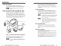
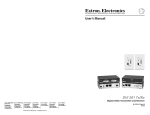
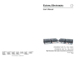
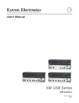
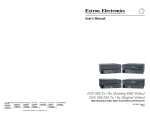
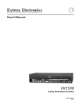
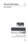
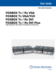
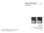
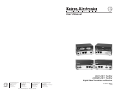
User’s Manual DVI 201 Tx/Rx HDMI 201 Tx/Rx Digital Video Transmitter and Receiver www.extron.com Extron Electronics, USA Extron Electronics, Europe Extron Electronics, Asia Extron Electronics, Japan 1230 South Lewis Street Anaheim, CA 92805 USA 714.491.1500 Fax 714.491.1517 Beeldschermweg 6C 3821 AH Amersfoort The Netherlands +31.33.453.4040 Fax +31.33.453.4050 135 Joo Seng Road, #04-01 PM Industrial Building Singapore 368363 +65.6383.4400 Fax +65.6383.4664 Kyodo Building 16 Ichibancho Chiyoda-ku, Tokyo 102-0082 Japan +81.3.3511.7655 Fax +81.3.3511.7656 © 2006 Extron Electronics. All rights reserved. 68-1034-01 Rev. C 07 06 Table of Contents Chapter One • Introduction .................................................... 1-1 About this Manual .................................................................... 1-2 About the DVI 201 Tx/Rx and HDMI 201 Tx/Rx ............... 1-2 TP cable advantages .............................................................. 1-3 Serial communications........................................................... 1-3 Transmission distance ............................................................ 1-3 Features ........................................................................................ 1-4 Chapter Two • Installation and Operation ................... 2-1 Mounting the Tx/Rx.................................................................. 2-2 Tabletop placement ............................................................... 2-2 Rack mounting ....................................................................... 2-2 Under-furniture mounting .................................................... 2-4 Through-furniture mounting ................................................ 2-5 Projector mounting ................................................................ 2-6 PMK 300 mounting .................................................................2-6 PMK 350 mounting .................................................................2-8 Connections ............................................................................... 2-10 Transmitter connections ...................................................... 2-10 Receiver connections ........................................................... 2-12 Pin assignments and wiring ................................................ 2-14 DVI connector pin assignments ...........................................2-14 HDMI connector pin assignments .......................................2-15 TP cable termination ............................................................2-16 Power supply wiring ............................................................2-18 RS-232 connector wiring ......................................................2-19 Operation ................................................................................... 2-20 Transmitter control and indicator ....................................... 2-21 Receiver indicator ................................................................ 2-21 System operation ................................................................. 2-21 Technical Points for Digital Video and Content Protection Encryption............................................ 2-21 Troubleshooting ....................................................................... 2-22 DVI 201 and HDMI 201 Tx/Rx • Table of Contents i Table of Contents, cont’d Appendix A • Reference Information..............................A-1 Specifications ..............................................................................A-2 DVI 201 and HDMI 201 Tx/Rx DVI 201 Tx/Rx Specifications .................................................A-2 HDMI 201 Tx/Rx Specifications .............................................A-5 Part Numbers ..............................................................................A-8 Transmitter/receiver pair part numbers ...............................A-8 Included Parts .........................................................................A-8 Mounting accessories ............................................................A-9 Cables......................................................................................A-9 Adapters .................................................................................A-9 1 Chapter One Introduction About this Manual About the DVI 201 Tx/Rx and HDMI 201 Tx/Rx Features 68-1034-01 Rev. C 07 06 All trademarks mentioned in this manual are the properties of their respective owners. ii DVI 201 and HDMI 201 Tx/Rx • Table of Contents Introduction About this Manual This manual contains information about the Extron DVI 201 Tx/Rx and HDMI 201 Tx/Rx transmitter and receiver pairs, including how to install, operate, and configure them. N In this manual, the term "Tx/Rx" refers to either product. About the DVI 201 Tx/Rx and HDMI 201 Tx/Rx The Extron DVI 201 Tx/Rx is a Digital Visual Interface (DVI) transmitter/receiver set. The HDMI 201 Tx/Rx is a High Definition Multimedia Interface (HDMI™) transmitter/receiver set. The transmitter/receiver sets extend the usable distance of DVI or HDMI digital video, and RS-232 control signals over two Category (CAT) 5/5e/6/7 twisted pair (TP) cables. The video and control signals can be transmitted up to 200' (60 m). LO CA UT UTP XS 0T LO Extron DVI 201 Tx T PU IN DV I DV ER IES CAT 5/5e/6/7 UTP up to 200’ Each pair ships with a single external desktop 12 V power supply that accepts 100 to 240 VAC, 50 Hz or 60 Hz input. A single power supply connected to either the transmitter or the receiver can power both units through one of the TP cables that link the units. TP cable advantages Twisted pair cable is much smaller, lighter, more flexible, and less expensive than coaxial or DVI or HDMI cable. These transmitter and receiver twisted pair (TP) products make cable runs simpler and less cumbersome. Termination of the cable with RJ-45 connectors is simple, quick, and economical. N The transmitter and receiver pair works with unshielded twisted pair (UTP) or shielded twisted pair (STP) cables; but, to ensure FCC Class A and CE compliance, STP cables are recommended. N Do not use Extron’s UTP23SF-4 Enhanced Skew-Free™ A/V UTP cable to link the transmitter and receiver. Skew-free A/V cable was designed for most Extron TP transmitter/receiver applications, but the Tx/Rx will not work properly with this cable. 20 Extron DVI 201 Rx Transmitter Receiver RS-232 Control DVI Cable I DV 0 20 -232RU RS TH Serial communications The RS-232 and/or Consumer Electronics Control (CEC) communications are via a passive pass-through only; the transmitter and receiver do not generate or respond to these signals. SS PA Tx Rx Transmission distance RS-232 Multimedia PC Projector Figure 1-1 — Typical transmitter and receiver application The transmitter and receiver pairs consists of a Tx transmitter and an Rx receiver that can handle a single link of DVI-D or HDMI digital video, depending on the model. N 1-2 The maximum distance is determined by the resolution of the signal and the UTP cable that is used. With CAT 5/5e/6 UTP cable, the Tx/Rx pair can transmit and receive 720p and 1080i HDTV or XGA video signals up to 200' (60 m) and 1080p HDTV or UXGA video up to 100' (30 m). With CAT 7 UTP cable, the Tx/Rx pair can transmit and receive 720p and 1080i HDTV or XGA video signals up to 200' (60 m) and 1080p HDTV or UXGA video up to 125' (38 m). The Tx/Rx is comprised of the transmitter-receiver pair. The transmitter and receiver cannot be purchased separately. DVI 201 and HDMI 201 Tx/Rx • Introduction DVI 201 and HDMI 201 Tx/Rx • Introduction 1-3 Introduction, cont’d Features Transmits single link DVI-D or HDMI signals over two CAT 5/5e/6/7 cables — Standard twisted pair cables provide an economical, easily installed cable solution. DVI 201 and HDMI 201 Tx/Rx Long distance transmission — CAT 5/5e/6 UTP cable — Accommodates 720p and 1080i HDTV or XGA video over 200' (60 m), and 1080p HDTV or UXGA (1600 x 1200) over 100' (30 m). CAT 7 UTP cable — Accommodates 720p and 1080i HDTV or XGA video over 200' (60 m), and 1080p HDTV or UXGA (1600 x 1200) over 125' (38 m). Local monitor output (DVI 201 Tx/Rx only) — The DVI 201 Tx transmitter features a DVI-D output for connection to local monitor. Supports DDC and HDCP copy protection transmission — The Tx/Rx pairs fully support long distance transmission of the DDC and HDCP signals. DDC routing to local or remote display (DVI 201 Tx/Rx only) — At the DVI 201 Tx, the DDC or HDCP signal is directed to either the local display or the remote display, depending on which is more critical in receiving the signal. Remote powering of transmitter or receiver — Only one power supply is necessary to power both devices. RS-232 pass-through — Bidirectional RS-232 control signals can be transmitted alongside the DVI or HDMI signal, so that the remote display can be controlled without the need for additional cabling. 2 Chapter Two Installation and Operation Supports CEC signal transmission 1" high, quarter rack width, metal enclosures — With low profile enclosures, both transmitter models and both receiver models can be discreetly installed in locations, such as behind a plasma or LCD flat-panel display. External 100 VAC to 240 VAC, 50/60 Hz, international power supply (part #70-055-01) included Mounting the Tx/Rx Connections Operation Technical Points for Digital Video and Content Protection Encryption Troubleshooting 1-4 DVI 201 and HDMI 201 Tx/Rx • Introduction Installation Mounting the Tx/Rx C Installation and service must be performed by authorized personnel only. VersaTools Rack Shelf The 1" high, quarter-rack width transmitters and receivers can be placed on a tabletop, mounted on a rack shelf, mounted under a desk or tabletop, or mounted on a projector bracket. Tabletop placement Affix the four included rubber feet to the bottom of the transmitter or receiver unit and place it in any convenient location. 1/4 Rack Width Front False Faceplate Rack mounting For optional rack mounting, mount the transmitter or receiver on any of the following rack shelves: ® • RSF 123 3" deep VersaTools rack shelf kit (part #60-19020) (figure 2-1) • RSB 123 3" deep VersaTools rack shelf (part #60-604-20) • RSU 126 6" deep universal rack shelf kit (part #60-190-10) • RSB 126 6" deep basic rack shelf (part #60-604-10) • RSU 129 9" deep 1U universal rack shelf kit (part #60-190-01) (figure 2-2) • RSB 129 9" deep 1U basic rack shelf (part #60-604-01) Use 2 mounting holes on opposite corners. (2) 4-40 x 3/16" Screws Figure 2-1 — Mounting the transmitter or receiver unit on a VersaTools rack shelf 1U Universal Rack Shelf 1/2 Rack Width Front False Faceplate 1/4 Rack Width Front False Faceplate On the non-VersaTools rack shelves, the transmitter or receiver unit can be mounted in the front or the rear of the rack. 1. Remove the feet from the bottom of the transmitter or receiver unit, if they are installed. 2. Mount the transmitter or receiver unit using two 4-40 x 3/16" screws in opposite (diagonal) corners to secure the transmitter or receiver to the shelf. 3. Both front false faceplates use 2 screws. Install false faceplate(s) or other unit(s) to the rack shelf. Use 2 mounting holes on opposite corners. (2) 4-40 x 3/16" Screws Figure 2-2 — Mounting the transmitter or receiver unit on a standard rack shelf 2-2 DVI 201 and HDMI 201 Tx/Rx • Installation DVI 201 and HDMI 201 Tx/Rx • Installation 2-3 Installation and Operation, cont’d Under-furniture mounting The transmitter or receiver can be mounted under a table or other horizontal surface using an optional Extron MBU 125 under-desk mounting kit (part #70-077-01). Mount the transmitter or receiver under a desk or table as follows: 1. Through-furniture mounting The transmitter or receiver can be mounted through a desk or other furniture using an optional Extron MBD 129 through-desk mounting kit, part #70-077-02. Mount the transmitter or receiver through a desk or table as follows (figure 2-4): Secure the under-desk mounting brackets to the transmitter or receiver with the four machine screws provided in the mounting kit (figure 2-3). Figure 2-4 — Through-desk mounting Figure 2-3 — Under-desk mounting 2. 3. 2-4 1. Hold the transmitter or receiver with attached brackets against the underside of the desk or other furniture. Mark the location of holes for screws on the desk. Loosely attach the mounting brackets to the transmitter or receiver using the four machine screws and washers supplied with the mounting kit. 2. Drill 1/4" (6.4 mm) deep, 3/32" (2 mm) diameter pilot holes in the table or desk at the marked screw locations from the underside or inside (the concealed side) of the furniture, where the transmitter or receiver will be located. Hold the transmitter or receiver against the inside of the surface through which it will be mounted. Mark the four screw holes on the inside of the surface to which you are mounting the device. 3. Drill four pilot holes, each 3/32" in diameter by 1/4" deep, where you made marks. 4. Using the four wood screws provided, secure the brackets to the mounting surface. 4. Insert the four wood screws into the pilot holes. Fasten each screw into the installation surface until just less than 1/4" of the screw head protrudes. 5. Align the installed screws with the slots in the mounting brackets, and place the transmitter or receiver against the surface, with the screws through the bracket slots. 6. Slide the transmitter or receiver slightly forward or back, then tighten all four screws to fasten it in place. DVI 201 and HDMI 201 Tx/Rx • Installation and Operation DVI 201 and HDMI 201 Tx/Rx • Installation and Operation 2-5 Installation and Operation, cont’d Slide the transmitter or receiver up and down in the mounting brackets until the face of the transmitter or receiver is at the desired height. Tighten the screws that secure the brackets in place. 5. If the screws are inaccessible to a screwdriver: Countoured Bracket Brace Side Mounting PLate U-Bolt Extron DVI 201 or HDMI 201 a. Mark the location of the brackets relative to the screws. Receiver b. Remove the transmitter or receiver from inside the furniture. Power Supply c. Tighten the screws. Extron PMK 300 d. Replace the unit inside the surface (step 4). Multi-product Projector Mount Kit Projector mounting Front Mounting PLate The receiver can be mounted on a projector bracket using either of the following optional Extron projector mounting kits: • PMK 300 projector mounting kit (part #70-374-01) • PMK 350 low profile projector mounting kit (part #70-563-02 [black] or part #70-563-03 [white]) PMK 300 mounting Mount the receiver to a PMK 300 bracket as follows: 1. If necessary, remove the feet from the bottom of the receiver. 2. Mount the receiver to one of the bracket’s three mounting plates using two of the supplied 4-40 x 3/16" screws in opposite (diagonal) corners to secure the device to the bracket. It can be vertically mounted facing either up or down (figure 2-5). N 3. 2-6 Contoured Bracket Brace Extron DVI 201 or HDMI 201 Receiver Power Supply U-Bolt Extron PMK 300 Multi-product Projector Mount Kit If power supply is connected to the receiver, use the two included tie wraps to strap the power supply to one of the brackets. N 4. On the side mounting plates, the device is typically mounted on the outside of the bracket. On the front mounting plate, the device is typically mounted on the inside of the bracket. Figure 2-5 — PMK 300 projector mounting a receiver The PMK 300 has a hole in the bottom plate that allows the projector pole to be inserted through the center of the plate (figure 2-6), rather than outside of the plate (figure 2-5). To install the PMK 300 in this configuration, slide the bracket up from the bottom of the pole before the projector is installed on the pole. Place the contoured bracket base against the pole and opposite the back plate. The pole should fit snugly into the depression in the center of the bracket base. DVI 201 and HDMI 201 Tx/Rx • Installation and Operation Figure 2-6 — Projector pole on the inside DVI 201 and HDMI 201 Tx/Rx • Installation and Operation 2-7 Installation and Operation, cont’d Place the U-bolt around the ceiling pole and insert the two legs of the U-bolt through the round holes on the contoured bracket base and then through the slotted holes on the bracket’s mounting plate. 5. N Assemble the U-bolt and the following parts in the following order (figure 2-8): 6. a. Pass the legs of the U-bolt through the slotted holes on the mount plate flange. The supplied U-bolt fits a typical (1.5" to 2.0" diameter) ceiling pole. b. Place the legs around the projector pole. c. Pass the legs through the holes in the contour base. Secure the bracket to the U-bolt with the included hex nuts, washers, and lock washers. Tighten the hex nuts just enough that they can be loosened by hand. 6. N d. Pass the legs through the holes in the L-shaped bracket. PMK 350 mounting Mount the receiver to a PMK 350 bracket as follows: N Remove the front and back plates from the PMK 350 (figure 2-7), using an Extron Tweeker or a #2 Philips screwdriver. Retain the screws to reattach the plates when you are finished. 1. The pole fits snugly into the depression in the center of the contoured base. The supplied U-bolt fits a typical (1.5" to 2.0" diameter) ceiling pole. Mount Plate Flange Contoured Base U-bolt L-shaped Bracket Extron Quarter-rack Sized Product Rear Plate Slotted Hole in PMK Tray L-shaped Bracket Screws Contoured Base Ceiling Pole L-shaped Bracket Extron PMK 350 U-bolt Figure 2-8 — Hanging the tray on the pole Multi-product Projector Mounting Kit Extron Power Supply 7. Align the two slotted holes in the bottom of the L-shaped bracket with the two slotted holes in the base of the tray,. Secure the L-bracket to the base by inserting two provided 6-32 x 5/16" screws through the aligned slots. 8. Move the PMK 350 up to the desired location on the ceiling pole, as close to the ceiling as desired. 9. Secure the L-shaped bracket to the U-bolt using the included hex nuts, washers, and lock washers. Tighten the hex nuts securely. Front Plate Cover Sheet Figure 2-7 — PMK 350 projector mounting a receiver 2. If necessary, remove the feet from the bottom of the receiver. 3. Secure the receiver to one side of the mounting tray, using two of the supplied 4-40 x 3/16" screws in opposite (diagonal) corners. 4. If power supply is connected to the receiver, use the two included tie wraps to strap the power supply to the bracket. 5. 2-8 Place the PMK 350 around the projector ceiling mounting pole (figure 2-7). DVI 201 and HDMI 201 Tx/Rx • Installation and Operation N Be sure to tighten the hex nuts securely enough that the PMK 350 does not slide down the ceiling pole. A socket wrench is recommended to tighten the hex nuts. 10. Secure the front panel to the mounting tray with four of the included #6 screws. 11. If desired, choose one of the provided four sizes of selfadhesive cover sheets, and apply it to the underside of the mounting tray. DVI 201 and HDMI 201 Tx/Rx • Installation and Operation 2-9 Installation and Operation, cont’d b Connections Transmitter connections The two transmitter models are in quarter-rack width enclosures. On the DVI 201 Tx (figure 2-9), the input and local monitor connectors are on the front panel and the rest of the connectors are on the rear panel. 1 2 DVI INPUT LOCAL OUTPUT DVI 200 Tx Series Front Panel c d e Rear Panel POWER 12V 0.4A MAX REMOTE LOCAL 1 2 5 6 On the HDMI 201 Tx (figure 2-10), all connectors are on the rear panel. The HDMI 201 Tx does not have a local output connector. HDMI 201 Tx HDMI INPUT RS-232 PASS THRU 1 3 2 5 DVI 201 and HDMI 201 Tx/Rx • Installation and Operation Connect transmitter output 1 to receiver input 1. Connect transmitter output 2 to receiver input 2. N If necessary, test for proper cable connection (output 1 to input 1, output 2 to input 2) as follows: 1. Plug both TP cables into the powered unit. 2. Momentarily connect either of the cables on the opposite end into the unpowered unit‘s “2” connector. If the unpowered unit’s Power LED is not lit, quickly unplug the connector on the unpowered end and connect the other cable to the “2” connector. 6 Figure 2-10 — HDMI 201 Tx transmitter’s rear panel connectors 2-10 N If the unpowered unit’s Power LED is lit, the connection is correct. Tx Rx DVI input connector (DVI 201 Tx) — Connect a DVI cable between this port and the DVI output port of the digital video source. See DVI connector pin assignments on page 2-14 for pin assignments. Do not connect these devices to a computer data or telecommunications network. Connect the free ends of the same TP cables from the transmitter to the receiver’s Input RJ-45 female connectors (item i on page 2-13). Tx Rx Figure 2-9 — DVI 201 Tx transmitter’s front and rear panel connectors a Transmitter output connector — Connect one end of two separate TP cables to these RJ-45 female connectors on the transmitter. RS-232 4 4 DC power input connector — Plug the included external 12 VDC power supply into either this 2-pole captive screw connector or the power input connector on the receiver (item h on page 2-13). See Power supply wiring, on page 2-18, to wire the connector. PASS THRU SPARE POWER 12V 0.4A MAX HDMI input connector (HDMI 201 Tx) — Connect an HDMI cable between this port and the HDMI output port of the digital video source. See HDMI connector pin assignments on page 2-15 for pin assignments. C DVI 201 Tx DDC ROUTE Local output (DVI 201 Tx) — If desired, connect a DVI monitor for local monitoring of the input digital image. See DVI connector pin assignments on page 2-14 for pin assignments. See TP cable termination, on page 2-16, to properly wire the RJ-45 connectors. f RS-232 connector — Connect a serial communications port to this 3.5 mm, 3-pole captive screw connector for bidirectional RS-232 communication. See RS-232 connector wiring, on page 2-19, to wire the connector. DVI 201 and HDMI 201 Tx/Rx • Installation and Operation 2-11 Installation and Operation, cont’d Receiver connections The two transmitter models are in quarter-rack width enclosures. On the DVI 201 Rx (figure 2-11), the RS-232 Pass-Through connector is on the front panel and the rest of the connectors are on the rear panel. 7 h i Receiver input connector — Connect one end of the two separate TP cables from the transmitter (item e on page 2-11) to these RJ-45 female connectors. C RS-232 PASS THRU Tx Rx DC power input connector — Plug the included external 12 VDC power supply into either this 2-pole captive screw connector or the power input connector on the transmitter (item d on page 2-11). See Power supply wiring, on page 2-18, to wire the connector. DVI 200 Rx Series N Connect transmitter output 1 to receiver input 1. Connect transmitter output 2 to receiver input 2. N If necessary, test for proper cable connection (output 1 to input 1, output 2 to input 2) as follows: Front Panel Rear Panel DVI 201 Rx POWER 12V 0.4A MAX 1 8 DVI OUTPUT 2 9 10 1 8 11 7 Figure 2-12 — HDMI 201 Rx Receiver’s rear panel connectors g 2-12 j Tx Rx 2 9 RS-232 2. Momentarily connect either of the cables on the opposite end into the unpowered unit‘s “2” connector. See TP cable termination, on page 2-16, to properly wire the RJ-45 connectors. HDMI 201 Rx PASS THRU Plug both TP cables into the powered unit. If the unpowered unit’s Power LED is not lit, quickly unplug the connector on the unpowered end and connect the other cable to the “2” connector. On the HDMI 201 Rx (figure 2-12), all connectors are on rear panel. HDMI OUTPUT 1. If the unpowered unit’s Power LED is lit, the connection is correct. Figure 2-11 — DVI 201 Rx Receiver’s front and rear panel connectors POWER 12V 0.4A MAX Do not connect these devices to a computer data or telecommunications network. k DVI Output connector — Connect a DVI monitor or projector for display of the transmitted direct digital image. See DVI connector pin assignments on page 2-14 for pin assignments. HDMI Output connector — Connect a HDMI monitor or projector for display of the transmitted direct digital image. See HDMI connector pin assignments on page 2-15 for pin assignments. RS-232 connector — Connect a serial communications port to this 3.5 mm, 3-pole captive screw connector for bidirectional RS-232 communication. See RS-232 connector wiring, on page 2-19 to wire the connector. DVI 201 and HDMI 201 Tx/Rx • Installation and Operation DVI 201 and HDMI 201 Tx/Rx • Installation and Operation 2-13 Installation and Operation, cont’d HDMI connector pin assignments Pin assignments and wiring Figure 2-14 define the pinout for the HDMI protocol. DVI connector pin assignments 1 Figure 2-13 define the pinout for the DVI protocol. 9 1 8 17 24 19 18 Male Connector Female Connector Pin Signal Pin Signal Pin Signal 1 TMDS data 2– 9 TMDS data 1– 17 TMDS data 0– 2 TMDS data 2+ 10 TMDS data 1+ 18 TMDS data 0+ 3 TMDS data 2 shield 11 TMDS data 1 shield 19 TMDS data 0 shield 4 Spare 12 Spare 20 5 Spare 13 Spare 19 1 2 2 18 HDMI HDMI Type A Receptacle Type A Plug Pin Signal Pin Signal Pin Signal 1 TMDS data 2+ 7 TMDS data 0– 13 CEC control* 2 TMDS data 2 shield 8 TMDS data 0 shield 14 Reserved (NC) 3 TMDS data 2- 9 TMDS data 0- 15 SCL Spare 4 TMDS data 1+ 10 TMDS clock+ 16 SDA 21 Spare 5 11 TMDS clock shield TMDS clock- 17 6 TMDS data 1 shield TMDS data 1- DDC / CEC Ground +5 V power 6 DDC clock 14 +5 V power 22 TMDS clock Shield 7 DDC data 15 Ground (+5 V) 23 TMDS clock+ 8 CEC control* 16 Hot Plug Detect 24 TMDS clock– * CEC control on pin 8 is a proprietary usage, not the industry standard. 12 * CEC control on pin 13 is a proprietary usage, not the industry standard. 18 19 Hot plug detect Figure 2-14 — HDMI connectors Figure 2-13 — DVI connectors 2-14 DVI 201 and HDMI 201 Tx/Rx • Installation and Operation DVI 201 and HDMI 201 Tx/Rx • Installation and Operation 2-15 Installation and Operation, cont’d N TP cable termination N RJ-45 termination with CAT 5, CAT 5e, CAT 6, or CAT 7 cable must comply with the TIA/EIA T 568A wiring standard for all connections. Figure 2-15 details the recommended termination of TP cables with RJ-45 connectors in accordance with the TIA/EIA T 568A wiring standard. Side RJ-45 Connector Pin Wire color 12345678 1 White-green Data 0+ CEC Green Data 0– HPD 3 White-orange ID Clock+ RS-232 TX 4 Blue Data 1+ DDC Clk 5 White-blue Data 1– +12 V 6 Orange ID Clock– RS-232 RX 7 White-brown Data 2+ DDC data 8 Brown Data 2– Ground 1&2 7&8 3&6 4&5 2. Momentarily connect either of the cables on the opposite end into the unpowered unit‘s “2” connector. Terminating shielded cable N The transmitter and receiver pair works with unshielded twisted pair (UTP) or shielded twisted pair (STP) cables; but, to ensure FCC Class A and CE compliance, STP cables are recommended. The Tx/Rx includes four shielded RJ-45 connectors and a length of self-adhesive shielded tape that you can use to make the STP cables that connect the transmitter and receiver. N Twisted Pairs Plug both TP cables into the powered unit. If the unpowered unit’s Power LED is not lit, quickly unplug the connector on the unpowered end and connect the other cable to the “2” connector. Signal RJ-45 #2 RJ-45 #1 2 1. If the unpowered unit’s Power LED is lit, the connection is correct. Clip Down Pins 1 2 3 4 5 6 7 8 If necessary, test for proper cable connection (output 1 to input 1, output 2 to input 2) as follows: Extron supplies the connectors and the shielded tape. You must supply the CAT 5, 5e, 6, or 7 STP cable. Terminate the STP cable as follows: 1. Peel back the cable shielding (figure 2-16) from the end of the cable the length of the RJ-45 connector body (approximately 7/8" [2.2 cm]) and fold it back. Figure 2-15 — TP cable termination N Do not use Extron’s UTP23SF-4 Enhanced Skew-Free™ A/V UTP cable to link the transmitter and receiver. Skew-free A/V cable was designed for most Extron TP transmitter/receiver applications, but the DVI or HDMI Tx/Rx will not work properly with this cable. Peel back shield and fold back. Figure 2-16 — Peeling back the cable shielding 2. 2-16 DVI 201 and HDMI 201 Tx/Rx • Installation and Operation Cut away and discard the clear cellophane inner wrapper from the end of the cable back to the folded-over cable shielding. DVI 201 and HDMI 201 Tx/Rx • Installation and Operation 2-17 Installation and Operation, cont’d 3. Peel the backing off the self-adhesive shielded aluminum tape and wrap it around the folded-over cable shielding, slightly overlapping the beginning of the tape (figure 2-17). Smooth Ridges A A SECTION A–A Aluminum Tape Wrap tape around folded foil shielding. Slightly overlap. Cut and save the excess tape for other connectors. Power Supply Output Cord Tie Wrap 0.3” (7 mm) MAX. DC Power Cord (between power supply and DVI/HDMI unit power connector) Ferrite Bead Figure 2-17 — Wrapping the shielded tape 4. Cut the unused portion of the shielded tape and retain for shielding other RJ-45 connectors. 5. Crimp the RJ-45 cable in the normal manner, folding the tangs at the end of the connector over the shielded tape (figure 2-18). Figure 2-19 — Power connector wiring C N Crimped Connector Figure 2-18 — Crimped RJ-45 connector C Power supply voltage polarity is critical. Incorrect voltage polarity can damage the power supply and the transmitter or receiver. Identify the power cord negative lead by the ridges on the side of the cord (figure 2-19). To verify the polarity before connection, plug in the power supply with no load and check the output with a voltmeter. W The two power cord wires must be kept separate while the power supply is plugged in. Remove power before wiring. Use the supplied tie-wrap to strap the power cord to the extended tail of the connector. Your transmitter/receiver pair may have shipped with a blue captive screw connector. This blue connector can be plugged into either a blue or an orange power receptacle. The blue connector does not have the extended tail or the included tie-wrap. A power supply connected to either unit in the pair powers both units. Only one power supply is required. Figure 2-19 shows how to wire the connector. The length of the exposed (stripped) copper wires is important. With the orange power connector, the ideal length is 0.3" (7 mm). Longer bare wires can short together. Shorter wires are not as secure in the connector and could be pulled out. The ideal length of exposed (stripped) copper wire for the blue connector is 0.2” (5 mm). Power supply wiring N Orange Captive Screw Connector N Do not tin the power supply leads before installing in the direct insertion connector. Tinned wires are not as secure in the connectors and could be pulled out of the connector. Snap the provided ferrite bead onto the DC power cable, between the power supply and the DVI unit’s connector. RS-232 connector wiring Figure 2-20 shows how to wire the RS-232 connector. Connected RS-232 Device Pins Receive Transmit Ground Tx/Rx Pins Tx Rx Gnd Figure 2-20 — RS-232 connector wiring 2-18 DVI 201 and HDMI 201 Tx/Rx • Installation and Operation DVI 201 and HDMI 201 Tx/Rx • Installation and Operation 2-19 Installation and Operation, cont’d Transmitter control and indicator Operation DVI INPUT a LOCAL OUTPUT DVI 200 Tx SERIES b DVI 201 Tx Transmitter Front Panel 1 POWER 12V 0.4A MAX DVI 201 Tx DDC ROUTE REMOTE RS-232 PASS THRU SPARE 2 LOCAL 1 2 Power LED — This transmitter front panel LED lights to indicate that the unit is receiving power. DDC Route switch (DVI 201 Tx only) — This transmitter rear panel switch selects either the remote or local DVI display as the route of the display resolution data (the display data channel [DDC]) and HDCP copyright decoding keys. Receiver indicator a Power LED — This receiver front panel LED lights to indicate that the unit is receiving power. Tx Rx DVI 201 Tx Transmitter Rear Panel RS-232 PASS THRU System operation After the transmitter, the receiver, and their connected devices are powered up, the system is fully operational. If any problems are encountered, ensure all cables are routed and connected properly. N Tx Rx 1 DVI 200 Rx SERIES DVI 201 Rx Receiver Front Panel HDMI 201 1 HDMI 201 Tx Transmitter Front Panel Technical Points for Digital Video and Content Protection Encryption • Digital Visual Interface (DVI) is a digital video format that was created by the computer industry in 1999. • High Definition Multimedia Interface (HDMI™) is a multimedia format that was created by the consumer video industry in 2003. The HDMI format is built onto the DVI format, adding digital audio and control while reducing the size of the connector. The HDMI format is likely to replace the DVI format in the near future. With passive adapters, the HDMI format is backward compatible with the DVI format. HDMI 201 1 HDMI 201 Rx Receiver Front Panel Figure 2-21 — Front and rear panel controls and indicators • 2-20 DVI 201 and HDMI 201 Tx/Rx • Installation and Operation Ensure that the video source and display selected for the DDC are properly connected to the transmitter/receiver pair, and that the transmitter, the receiver, and the display have power applied before power is applied to the video source. If all other devices are not turned on before the video source, the image may not appear. With Extron adapters and/or cables, the DVI 201 fully supports either format, regardless of the connector type on the video source and display. See appendix A, Reference Information, for part numbers. DVI 201 and HDMI 201 Tx/Rx • Installation and Operation 2-21 Installation and Operation, cont’d • High-bandwidth Digital Content Protection (HDCP) is an encryption method that protects copyrighted digital entertainment material that uses DVI video. HDCP is generated by video player hardware, enabled by the video content. The HDCP key is transmitted with the Display Data Channel (DDC). The DDC signal line was designed for the DDC’s low data rate; the HDCP key rate is much higher. ♦ Without active buffering, an HDCP key signal can travel only a short distance. The display may properly receive the digital video signal, but not the HDCP key. Without the key, the display cannot decrypt the video signal. Symptoms of undecrypted video may include a flashing black or blue screen or “snow”. ♦ With active buffering, an HDCP key signal can travel as far as other signals to ensure proper decryption. ♦ The DVI 201 and the HDMI 201 actively buffer the HDCP key. Troubleshooting DVI/HDMI signals run at a very high frequency and are especially susceptible to bad video connections, too many adapters, or cables that are too long. To avoid the loss of an image or introduction of image jitter, follow these guidelines: • The DVI/HDMI cable on the input to the transmitter or the output of the receiver should not exceed 10' (3 meters). • Use only cable designed for DVI/HDMI signals. • Limit or avoid the use of adapters. • If the display exhibits a flashing black or blue screen, snow, or other distortion, a non-HDCP compliant display may be receiving an HDCP-encrypted signal. Check for an HDCP problem by ejecting the DVD from the player. If the display distortion stops and the DVD menu or screensaver image is clear, the problem is HDCP-related. 2-22 DVI 201 and HDMI 201 Tx/Rx • Installation and Operation DVI 201 and HDMI 201 Tx/Rx A Appendix A Reference Information Specifications Part Numbers Reference Information Specifications DVI 201 Tx/Rx Specifications N This product consists of a transmitter (DVI 201 Tx) and a receiver (DVI 201 Rx) with twisted pair cables linking the transmitter and receiver. Interconnection between transmitter and receiver Connectors ..................................... (2) RJ-45 per unit for 2 CAT 5/5e/6 cables connecting the transmitter and receiver Bit rate ............................................. 5 gigabits/second total (1.65 gigabits/ second/color) Signal transmission distance 1600x1200 @ 60 Hz (the highest resolution of the single link DVI standard) CAT 7 cable ................ 125' (38 m) CAT 5/5e/6 cable...... 100' (30 m) HDTV (1080i or 720p) or 1024x768 @ 60 Hz CAT 5/5e/6/7 cable . 200' (60 m) N The transmission distance varies greatly depending on the signal resolution and on the type of cable, graphic card, and display used in the system. Signal types and standards Digital video ................................ RGB digital video (DVI and HDMI* standards), actively buffered YCrCb digital component video (HDMI standard), actively buffered (All single link DVI and HDMI* signal formats are supported including 640x480 @ 60 Hz through 1600x1200 @ 60 Hz computer video, and also 480p, 720p, 1080i, and 1080p HDTV signals) N *An optional HDMI to DVI adapter is required if an HDMI signal is used. HDCP ............................................. HDCP (High-bandwidth Digital Content Protection) using the DVI and HDMI standards (for video, actively buffered, transmitted through DDC lines) N A-2 Digital audio ................................ HDMI* audio, actively buffered (transmitted through RGB and YCrCb lines) N *An optional HDMI to DVI adapter is required if an HDMI signal is used. RS-232 ............................................ RS-232 serial data (pass-through) CEC ................................................ Consumer Electronics Control (CEC) wired infrared data using the HDMI standard (pass-through) N *An optional Extron HDMI to DVI adapter is required in order to transmit a CEC signal. EDID (DDC) ................................. EDID (Extended Display Identification Data) and DDC (display data channel) using DVI and HDMI* standards (actively buffered) N *An optional HDMI to DVI adapter is required if an HDMI signal is used. HPD ............................................... HPD (Hot Plug Detection of display, passthrough) Video input and loop-through (DVI 201 Tx) Number/signal type ..................... 1 DVI-D/HDMI* input, 1600x1200 @ 60 Hz max. resolution 1 DVI-D/HDMI* local loop-through N *An optional HDMI to DVI adapter is required if an HDMI signal is used. Connectors ..................................... 2 DVI-D female Video output (DVI 201 Rx) Number/signal type ..................... 1 DVI-D/HDMI*, 1600x1200 @ 60 Hz max. resolution N *An optional HDMI to DVI adapter is required if an HDMI signal is used. Connectors ..................................... 1 DVI-D female *An optional HDMI to DVI adapter is required if an HDMI signal is used. DVI 201 and HDMI 201 Tx/Rx • Reference Information DVI 201 and HDMI 201 Tx/Rx • Reference Information A-3 Reference Information, cont’d General HDMI 201 Tx/Rx Specifications External power supply ................. 100 VAC to 240 VAC, 50/60 Hz, external, autoswitchable; to 12 VDC, 1 A, regulated Power input requirements ........... 12 VDC, 0.4 A for both transmitter and receiver N Each transmitter or receiver can be powered either locally by an external power supply or remotely by receiver or transmitter on the other end of the CAT 5/5e/6 cables. Temperature/humidity ................ Storage: -40 to +158 °F (-40 to +70 °C) / 10% to 90%, noncondensing Operating: +32 to +122 ° F (0 to +50 °C) / 10% to 90%, noncondensing Rack mount .................................... Yes, with optional RSU 129 or RSB 129 1U 9" rack shelf, part #60-190-01 or 60-604-01; RSU 126 or RSB 126 6" 1U deep rack shelf, part #60-190-10 or 60-604-10; or the VersaTools® RSF 123 or RSB 123 3" 1U rack shelf, part #60-190-20 or 60-604-20. Also furniture mountable with optional MBD 129 through-desk mount kit, #70-077-02, or attachable to a projector mount using an optional PMK 300 or PMK 350 projector mount kit, #70-374-01 or 70-563-02/03. Enclosure type ............................... Metal Enclosure dimensions ................... 1.0" H x 4.3" W x 3.0" D (quarter rack wide) 2.5 cm H x 10.9 cm W x 7.6 cm D (Depth excludes connectors.) Product weight .............................. 0.5 lbs (0.3 kg) Shipping weight ............................ 3 lbs (2 kg) Vibration ......................................... ISTA 1A in carton (International Safe Transit Association) Listings............................................ UL, CUL Compliances................................... CE, FCC Class A, VCCI, AS/NZS, ICES MTBF............................................... 30,000 hours Warranty ......................................... 3 years parts and labor N All nominal levels are at ±10%. N Specifications are subject to change without notice. A-4 DVI 201 and HDMI 201 Tx/Rx • Reference Information N This product consists of a transmitter (HDMI 201 Tx) and a receiver (HDMI 201 Rx) with twisted pair cables linking the transmitter and receiver. Video input (HDMI 201 Tx) Number/signal type ..................... 1 single link HDMI input Connectors .................................... 1 HDMI female Interconnection between transmitter and receiver Connectors ..................................... (2) RJ-45 per unit for 2 CAT 5/5e/6/7 cables connecting the transmitter and receiver Bit rate ............................................. 5 gigabits per second total (1.65 gigabits per second per color) Signal transmission distance HDTV (1080i or 720p) or 1024x768 @ 60 Hz CAT 5/5e/6/7 cable . 200' (60 m) HDTV (1080p) or 1600x1200 @ 60 Hz (the highest resolution of the single link DVI standard) CAT 7 cable ................ 125' (38 m) CAT 5/5e/6 cable...... 100' (30 m) N The transmission distance varies greatly depending on the signal resolution and on the type of cable, graphic card, and display used in the system. Signal types and standards Digital video ................................ RGB digital video (DVI and HDMI standards), actively buffered YCrCb digital component video (HDMI standard), actively buffered (All single link DVI and HDMI signal formats are supported including 640x480 @ 60 Hz through 1600x1200 @ 60 Hz computer video, and also 480p, 720p, 1080i, and 1080p HDTV signals) HDCP ............................................. HDCP (High-bandwidth Digital Content Protection) using the DVI and HDMI standards (for video, actively buffered, transmitted through DDC lines) DVI 201 and HDMI 201 Tx/Rx • Reference Information A-5 Reference Information, cont’d Digital audio ................................ HDMI audio, actively buffered (transmitted through RGB and YCrCb lines) RS-232 ............................................ RS-232 serial data (pass-through) (on a 3.5 mm captive screw connector, 3 pole) CEC ................................................ Consumer Electronics Control (CEC) wired infrared data using the HDMI standard (pass-through) EDID (DDC) ................................. EDID (Extended Display Identification Data) and DDC (display data channel) using DVI and HDMI standards (actively buffered) HPD ............................................... HPD (Hot Plug Detection of display, passthrough) Video output (HDMI 201 Rx) Number/signal type ..................... 1 single link HDMI Connectors .................................... 1 HDMI female Enclosure type .............................. Metal Enclosure dimensions .................. 1.0" H x 4.3" W x 3.0" D (quarter rack wide) 2.5 cm H x 10.9 cm W x 7.6 cm D (Depth excludes connectors.) Product weight .............................. 0.5 lbs (0.3 kg) Shipping weight ........................... 3 lbs (2 kg) Vibration ........................................ ISTA 1A in carton (International Safe Transit Association) Listings............................................ UL, CUL Compliances................................... CE, FCC Class A, VCCI, AS/NZS, ICES MTBF............................................... 30,000 hours Warranty ........................................ 3 years parts and labor N All nominal levels are at ±10%. N Specifications are subject to change without notice. General External power supply ................. 100 VAC to 240 VAC, 50/60 Hz, 6 W max., external, autoswitchable; to 12 VDC, 1 A, regulated Power input requirements ........... 12 VDC, 0.4 A for both transmitter and receiver N Each transmitter or receiver can be powered either locally by an external power supply or remotely by receiver or transmitter on the other end of the CAT 5/5e/6/7 cables. Temperature/humidity ................ Storage: -40 to +158 ° F (-40 to +70 ° C) / 10% to 90%, noncondensing Operating: +32 to +122 ° F (0 to +50 ° C) / 10% to 90%, noncondensing Rack mount .................................... Yes, with optional RSU 129 or RSB 129 1U rack shelf, part #60-190-01 or 60-604-01; RSU 126 or RSB 126 6" deep rack shelf, part #60-190-10 or 60-604-10; or the VersaTools® RSF 123 or RSB 123 rack shelf, part #60-190-20 or 60-604-20. Also furniture mountable with optional MBD 129 through-desk mount kit, #70-077-02, or attachable to a projector mount using an optional PMK 300 or PMK 350 projector mount kit, #70-374-01 or 70-563-02/03. A-6 DVI 201 and HDMI 201 Tx/Rx • Reference Information DVI 201 and HDMI 201 Tx/Rx • Reference Information A-7 Reference Information, cont’d Mounting accessories Part Numbers Accessories Transmitter/receiver pair part numbers N The Tx/Rx is comprised of the transmitter-receiver pair. The transmitter and receiver cannot be purchased separately. Model and included parts Part number ® Part number RSF 123 3" VersaTools rack shelf kit 60-190-20 RSB 123 3" VersaTools rack shelf 60-604-20 RSU 126 6" deep universal rack shelf kit 60-190-10 RSB 126 6" deep basic rack shelf 60-604-10 DVI 201 Tx/Rx 60-734-03 RSU 129 9" 1U universal rack shelf kit 60-190-01 HDMI 201 Tx/Rx 60-806-01 RSB 129 9" 1U basic rack shelf 60-604-01 MBU 125 under-desk mount kit 70-077-01 MBD 129 through-desk mount kit 70-077-02 PMK 300 projector mount kit 70-374-03 Included Parts These items are included in each order for a DVI 201 Tx/Rx or HDMI 201 Tx/Rx: Model and included parts Part number DVID SL/6 (with DVI 201) DVI-D male-to-male, 6' (1.8 m) cable 26-585-02 HDMI M-M/6 (with HDMI 201) HDMI male-to-male, 6' (1.8 m) cable 26-613-02 PMK 350 low profile projector mount kit (black, white) 70-563-02, -03 Accessories Part number Cables 12 VDC, 1 A external power supply 70-055-01 3.5 mm, 2-pole captive screw connector 10-319-13 (2) 3.5 mm, 3-pole captive screw connectors 10-319-15 IEC power cord Tweeker (small screwdriver) User’s manual DVID SL/6 DVI-D male-to-male, 6' (1.8 m) cable 26-585-02 HDMI M-M/6 HDMI male to male, 6’ (1.8 m) 26-613-02 HDMI M-DVI-DM/6 HDMI male to DVI-D male, 6’ (1.8 m) 26-614-02 Adapters Accessories A-8 DVI 201 and HDMI 201 Tx/Rx • Reference Information Part number HDMIF-DVIDM HDMI female to DVI-D male adapter 26-616-01 HDMIM-DVIDF HDMI male to DVI-D female adapter 26-617-01 DVI 201 and HDMI 201 Tx/Rx • Reference Information A-9 Reference Information, cont’d A-10 DVI 201 and HDMI 201 Tx/Rx • Reference Information Precautions Safety Instructions • English This symbol is intended to alert the user of important operating and maintenance (servicing) instructions in the literature provided with the equipment. This symbol is intended to alert the user of the presence of uninsulated dangerous voltage within the product’s enclosure that may present a risk of electric shock. Caution Read Instructions • Read and understand all safety and operating instructions before using the equipment. Retain Instructions • The safety instructions should be kept for future reference. Follow Warnings • Follow all warnings and instructions marked on the equipment or in the user information. Avoid Attachments • Do not use tools or attachments that are not recommended by the equipment manufacturer because they may be hazardous. Consignes de Sécurité • Français Ce symbole sert à avertir l’utilisateur que la documentation fournie avec le matériel contient des instructions importantes concernant l’exploitation et la maintenance (réparation). Ce symbole sert à avertir l’utilisateur de la présence dans le boîtier de l’appareil de tensions dangereuses non isolées posant des risques d’électrocution. Attention Lire les instructions• Prendre connaissance de toutes les consignes de sécurité et d’exploitation avant d’utiliser le matériel. Conserver les instructions• Ranger les consignes de sécurité afin de pouvoir les consulter à l’avenir. Respecter les avertissements • Observer tous les avertissements et consignes marqués sur le matériel ou présentés dans la documentation utilisateur. Eviter les pièces de fixation • Ne pas utiliser de pièces de fixation ni d’outils non recommandés par le fabricant du matériel car cela risquerait de poser certains dangers. Sicherheitsanleitungen • Deutsch Dieses Symbol soll dem Benutzer in der im Lieferumfang enthaltenen Dokumentation besonders wichtige Hinweise zur Bedienung und Wartung (Instandhaltung) geben. Dieses Symbol soll den Benutzer darauf aufmerksam machen, daß im Inneren des Gehäuses dieses Produktes gefährliche Spannungen, die nicht isoliert sind und die einen elektrischen Schock verursachen können, herrschen. Achtung Lesen der Anleitungen • Bevor Sie das Gerät zum ersten Mal verwenden, sollten Sie alle Sicherheits-und Bedienungsanleitungen genau durchlesen und verstehen. Aufbewahren der Anleitungen • Die Hinweise zur elektrischen Sicherheit des Produktes sollten Sie aufbewahren, damit Sie im Bedarfsfall darauf zurückgreifen können. Befolgen der Warnhinweise • Befolgen Sie alle Warnhinweise und Anleitungen auf dem Gerät oder in der Benutzerdokumentation. Keine Zusatzgeräte • Verwenden Sie keine Werkzeuge oder Zusatzgeräte, die nicht ausdrücklich vom Hersteller empfohlen wurden, da diese eine Gefahrenquelle darstellen können. Instrucciones de seguridad • Español Este símbolo se utiliza para advertir al usuario sobre instrucciones importantes de operación y mantenimiento (o cambio de partes) que se desean destacar en el contenido de la documentación suministrada con los equipos. Este símbolo se utiliza para advertir al usuario sobre la presencia de elementos con voltaje peligroso sin protección aislante, que puedan encontrarse dentro de la caja o alojamiento del producto, y que puedan representar riesgo de electrocución. Precaucion Leer las instrucciones • Leer y analizar todas las instrucciones de operación y seguridad, antes de usar el equipo. Conservar las instrucciones • Conservar las instrucciones de seguridad para futura consulta. Obedecer las advertencias • Todas las advertencias e instrucciones marcadas en el equipo o en la documentación del usuario, deben ser obedecidas. Evitar el uso de accesorios • No usar herramientas o accesorios que no sean especificamente recomendados por el fabricante, ya que podrian implicar riesgos. FCC Class A Notice Warning Power sources • This equipment should be operated only from the power source indicated on the product. This equipment is intended to be used with a main power system with a grounded (neutral) conductor. The third (grounding) pin is a safety feature, do not attempt to bypass or disable it. Power disconnection • To remove power from the equipment safely, remove all power cords from the rear of the equipment, or the desktop power module (if detachable), or from the power source receptacle (wall plug). Power cord protection • Power cords should be routed so that they are not likely to be stepped on or pinched by items placed upon or against them. Servicing • Refer all servicing to qualified service personnel. There are no userserviceable parts inside. To prevent the risk of shock, do not attempt to service this equipment yourself because opening or removing covers may expose you to dangerous voltage or other hazards. Slots and openings • If the equipment has slots or holes in the enclosure, these are provided to prevent overheating of sensitive components inside. These openings must never be blocked by other objects. Lithium battery • There is a danger of explosion if battery is incorrectly replaced. Replace it only with the same or equivalent type recommended by the manufacturer. Dispose of used batteries according to the manufacturer’s instructions. Note: This equipment has been tested and found to comply with the limits for a Class A digital device, pursuant to part 15 of the FCC Rules. These limits are designed to provide reasonable protection against harmful interference when the equipment is operated in a commercial environment. This equipment generates, uses and can radiate radio frequency energy and, if not installed and used in accordance with the instruction manual, may cause harmful interference to radio communications. Operation of this equipment in a residential area is likely to cause harmful interference, in which case the user will be required to correct the interference at his own expense. Note: These units was tested with shielded cables on the peripheral devices and between the transmitter and receiver. Shielded cables must be used with the units to ensure compliance. Avertissement Alimentations• Ne faire fonctionner ce matériel qu’avec la source d’alimentation indiquée sur l’appareil. Ce matériel doit être utilisé avec une alimentation principale comportant un fil de terre (neutre). Le troisième contact (de mise à la terre) constitue un dispositif de sécurité : n’essayez pas de la contourner ni de la désactiver. Déconnexion de l’alimentation• Pour mettre le matériel hors tension sans danger, déconnectez tous les cordons d’alimentation de l’arrière de l’appareil ou du module d’alimentation de bureau (s’il est amovible) ou encore de la prise secteur. Protection du cordon d’alimentation • Acheminer les cordons d’alimentation de manière à ce que personne ne risque de marcher dessus et à ce qu’ils ne soient pas écrasés ou pincés par des objets. Réparation-maintenance • Faire exécuter toutes les interventions de réparationmaintenance par un technicien qualifié. Aucun des éléments internes ne peut être réparé par l’utilisateur. Afin d’éviter tout danger d’électrocution, l’utilisateur ne doit pas essayer de procéder lui-même à ces opérations car l’ouverture ou le retrait des couvercles risquent de l’exposer à de hautes tensions et autres dangers. Fentes et orifices • Si le boîtier de l’appareil comporte des fentes ou des orifices, ceux-ci servent à empêcher les composants internes sensibles de surchauffer. Ces ouvertures ne doivent jamais être bloquées par des objets. Lithium Batterie • Il a danger d’explosion s’ll y a remplacment incorrect de la batterie. Remplacer uniquement avec une batterie du meme type ou d’un ype equivalent recommande par le constructeur. Mettre au reut les batteries usagees conformement aux instructions du fabricant. Vorsicht Stromquellen • Dieses Gerät sollte nur über die auf dem Produkt angegebene Stromquelle betrieben werden. Dieses Gerät wurde für eine Verwendung mit einer Hauptstromleitung mit einem geerdeten (neutralen) Leiter konzipiert. Der dritte Kontakt ist für einen Erdanschluß, und stellt eine Sicherheitsfunktion dar. Diese sollte nicht umgangen oder außer Betrieb gesetzt werden. Stromunterbrechung • Um das Gerät auf sichere Weise vom Netz zu trennen, sollten Sie alle Netzkabel aus der Rückseite des Gerätes, aus der externen Stomversorgung (falls dies möglich ist) oder aus der Wandsteckdose ziehen. Schutz des Netzkabels • Netzkabel sollten stets so verlegt werden, daß sie nicht im Weg liegen und niemand darauf treten kann oder Objekte darauf- oder unmittelbar dagegengestellt werden können. Wartung • Alle Wartungsmaßnahmen sollten nur von qualifiziertem Servicepersonal durchgeführt werden. Die internen Komponenten des Gerätes sind wartungsfrei. Zur Vermeidung eines elektrischen Schocks versuchen Sie in keinem Fall, dieses Gerät selbst öffnen, da beim Entfernen der Abdeckungen die Gefahr eines elektrischen Schlags und/oder andere Gefahren bestehen. Schlitze und Öffnungen • Wenn das Gerät Schlitze oder Löcher im Gehäuse aufweist, dienen diese zur Vermeidung einer Überhitzung der empfindlichen Teile im Inneren. Diese Öffnungen dürfen niemals von anderen Objekten blockiert werden. Litium-Batterie • Explosionsgefahr, falls die Batterie nicht richtig ersetzt wird. Ersetzen Sie verbrauchte Batterien nur durch den gleichen oder einen vergleichbaren Batterietyp, der auch vom Hersteller empfohlen wird. Entsorgen Sie verbrauchte Batterien bitte gemäß den Herstelleranweisungen. Advertencia Alimentación eléctrica • Este equipo debe conectarse únicamente a la fuente/tipo de alimentación eléctrica indicada en el mismo. La alimentación eléctrica de este equipo debe provenir de un sistema de distribución general con conductor neutro a tierra. La tercera pata (puesta a tierra) es una medida de seguridad, no puentearia ni eliminaria. Desconexión de alimentación eléctrica • Para desconectar con seguridad la acometida de alimentación eléctrica al equipo, desenchufar todos los cables de alimentación en el panel trasero del equipo, o desenchufar el módulo de alimentación (si fuera independiente), o desenchufar el cable del receptáculo de la pared. Protección del cables de alimentación • Los cables de alimentación eléctrica se deben instalar en lugares donde no sean pisados ni apretados por objetos que se puedan apoyar sobre ellos. Reparaciones/mantenimiento • Solicitar siempre los servicios técnicos de personal calificado. En el interior no hay partes a las que el usuario deba acceder. Para evitar riesgo de electrocución, no intentar personalmente la reparación/mantenimiento de este equipo, ya que al abrir o extraer las tapas puede quedar expuesto a voltajes peligrosos u otros riesgos. Ranuras y aberturas • Si el equipo posee ranuras o orificios en su caja/alojamiento, es para evitar el sobrecalientamiento de componentes internos sensibles. Estas aberturas nunca se deben obstruir con otros objetos. Batería de litio • Existe riesgo de explosión si esta batería se coloca en la posición incorrecta. Cambiar esta batería únicamente con el mismo tipo (o su equivalente) recomendado por el fabricante. Desachar las baterías usadas siguiendo las instrucciones del fabricante. Extron’s Warranty Extron Electronics warrants this product against defects in materials and workmanship for a period of three years from the date of purchase. In the event of malfunction during the warranty period attributable directly to faulty workmanship and/or materials, Extron Electronics will, at its option, repair or replace said products or components, to whatever extent it shall deem necessary to restore said product to proper operating condition, provided that it is returned within the warranty period, with proof of purchase and description of malfunction to: USA, Canada, South America, and Central America: Extron Electronics 1001 East Ball Road Anaheim, CA 92805, USA Asia: Extron Electronics, Asia 135 Joo Seng Road, #04-01 PM Industrial Bldg. Singapore 368363 Europe, Africa, and the Middle East: Extron Electronics, Europe Beeldschermweg 6C 3821 AH Amersfoort The Netherlands Japan: Extron Electronics, Japan Kyodo Building 16 Ichibancho Chiyoda-ku, Tokyo 102-0082 Japan This Limited Warranty does not apply if the fault has been caused by misuse, improper handling care, electrical or mechanical abuse, abnormal operating conditions or nonExtron authorized modification to the product. If it has been determined that the product is defective, please call Extron and ask for an Applications Engineer at (714) 491-1500 (USA), 31.33.453.4040 (Europe), 65.6383.4400 (Asia), or 81.3.3511.7655 (Japan) to receive an RA# (Return Authorization number). This will begin the repair process as quickly as possible. Units must be returned insured, with shipping charges prepaid. If not insured, you assume the risk of loss or damage during shipment. Returned units must include the serial number and a description of the problem, as well as the name of the person to contact in case there are any questions. Extron Electronics makes no further warranties either expressed or implied with respect to the product and its quality, performance, merchantability, or fitness for any particular use. In no event will Extron Electronics be liable for direct, indirect, or consequential damages resulting from any defect in this product even if Extron Electronics has been advised of such damage. Please note that laws vary from state to state and country to country, and that some provisions of this warranty may not apply to you.