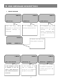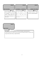
1
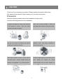
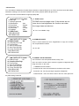
HIGH SPEED DOME CAMERA
User Manual
650 TVL
DSC-737SE
2
Table of contents
Ⅰ
CAUTION
---------
4
Ⅱ
INTRODUCTION OF PRODUCTS
---------
6
Ⅲ
DIRECTIONS FOR USE
--------- 14
Ⅳ
FUNCTIONAL SETTING BY THE KEYBOARD
--------- 27
Ⅴ
OSD MESSAGE DISCRIPTION
--------- 30
Ⅵ
TROUBLE SHOOTING
--------- 32
Ⅶ
DIMENSION
--------- 34
Ⅷ
ASSEMBLY
--------- 36
Ⅸ
SPECIFICATION
--------- 39
3
Ⅰ. CAUTION
Thank you for purchasing our product. Please operate the product after being
fully aware of the manual. Pease contact us if you have any queries.
Precaution
Note the following matters before the installation of the product.
Avoid the following places for the installation.
A high/low temperature: Using indoor-cameras
Snow, rain and wet: Humidity or water and
in the places of +50°C~ -10°C can cause
any liquid inside-camera can cause troubles.
troubles and lower its capacity.
Oil, gas: Oil and gas can damage the camera
Vibration, shock: They bring on problems or
as they go through the cameras.
errors of the camera.
Direct light, exposure to the air: In the case of
Closing to High frequency and electric power
that sets indoor- cameras outside where the
lines:
weather is changeable, it can cause problems.
electromagnetic units or power supplier can
Setting
bl
4
the
camera
up
around
Caution in Use
Do not disassemble the unit and put alien substances in the unit.
-
Disassembling the unit or putting alien substances such as a metal can make the
camera defective.
-
Make sure of power switch-off before the installation.
: Ensure power switch-off and check the voltage the camera before the installation.
- Do not give the unit a shock and an operation.
: Giving a strong shock or an excessive power on the button, terminal can cause
problem.
This product has been designed and manufactured in accordance with the harmonized
European standards, following the provisions of the below stated directives.
Electromagnetic Compatibility Directive 89/336/EEC
(EN60065:1998, EN61000-6-3:2001, EN61000-6-1:1997)
This devise complies with part 15 of the FCC rules operation is subject to the
following two conditions: (1) This device may not cause harmful interference and
(2) This device must accept any interference received including interference that
may cause undesired operation
Caution :
① Must use AC24V power source, current intensity must be less than 1.5A and
must use a double winding transformer
② Never extend the power line from adaptor to camera.
③ Please use more thick cable than 18AWG(1.0mm), if you want to
extend the power line.
④ You must use one adaptor per one camera that is being provided.
⑤ Use extra power supplier, If you want to supply many piece of
cameras.
5
Ⅱ. INTRODUCTION OF PRODUCT
1. DESCRIPTION AND FEATURES
Description
This camera has been designed elegantly for buildings, department stores that
need to be in harmony with the interior as a high speed dome camera, including
various observation functions.
Features
☺ High Resolution and Zoom Rate
High resolution 650 TVL with Sony 960H CCD and Built-in High Zoom (28X, 37X) Rate
Camera with 12x Digital Zoom
☺ A low light function
Surveillance with optimum picture is possible owing to digital-slow-shutter function.
Digital-slow-shutter function is improving the CCD sensitivity by electrically lengthening
exposure time so that it should be under surveillance on the condition of 0.00001Lux in
B/W
☺ Wide Dynamic Range + ACE
ACE can clearly distinguish objects in any location, including those with harsh lighting
such as backlit warehouses with extreme differences in brightness in which WDR may
not function properly.
☺Slow AE
This feature allows user to customize the exposure adjustment speed. This is useful for
monitoring of areas where lighting is prone to abrupt changes at night.
☺ 3D-DNR(Digital Noise Reduction )
3D-DNR removes image noise. If the scenes are not clear due to low brightness, the
function can make the image clean and obvious.
☺ Digital Image Stabilize
There is some tremble as zoom magnification is high, the function can compensate the
tremble.
☺ Auto Tilt Function
The unit can track the moving object automatically until 180° in vertical by using controller.
☺ 8 Privacy Masking Zones
For the privacy, it can be programmed for masking zone up to 8 locations on the OSD
menu screen.
☺ 250 Preset positions
A maximum of 250 preset positions can be programmed. The preset function enables to
set where you want on monitor at any time.
☺ Various auto-surveillance functions
Swing(2), Group(12 Presets), Tour(12 Groups), Spiral, Trace
☺Bad Pixel Correction
We can detect bad pixels based on the pattern of the surround pixels. We also support
on-the-fly
correction. (On–the–fly: automatically detect and correct bad pixel during sensor normal
operation)
☺ Smart pan/tilt function
Pan and tilt speed compensation function in proportion to depth of zoom.
6
2. INSTALLATION AND CONNECTION
1) Name and function of each part
Indoor Type
Outdoor Type
(UPPER COVER)
The camera’s body goes to
here and a power cable,
data cable, video cable,
sensor
have
been
connected with this
(DOME DRIVER)
A main body that has a
built-in the control units and
camera
(LOWER COVER)
Insert the body into the
upper cover, then close the
lower cover
7
2) Installation
Indoor Type
Outdoor Type
SEPARATION OF LOWER
COVER
(Indoor type)
Loosen the bolt of the back
of
lower
cover
by
a
screwdriver(+), then turn the
cover as above the picture
and pull the lower cover to
the down
(Outdoor type)
Loosen the four bolts of the
lower cover, then separate.
Loosen the three bolts, the
round head shaped, of the
camera body. The three bolts
are not loosened completely
and not come up more than
1cm of the lower cover, then
separate.
Pull
the
cover
up
with
grabbing the bottom of the
camera after loosening the
three bolts
8
Open the connector cover, then connect
power, data, video cable and sensor
The cover is opened if user loosens the
one bolt on the connector cover by using a
screwdriver(+).
The bolts not loosened completely to
protect from missing of them.
Be careful that each cable which each
function is changed wrong
Have you connect the power cable
in the right direction ?
If yes
① RED led, in the middle of the
connector, is lighted
② Use AC24V power source and
user can use any power input that is
connected with a terminal and a
jack (But use 1 input).
9
3) How to connect equipments
DC12V/1A adaptor and junction box are provided
on a purchase, Junction box consists of 2 data
ports ( Each data port can be connected with
maximum up to 128 cameras and sub keyboard
terminal
Connect the image
line of a monitor
Reference to the following page.
User can control maximum up to 255 cameras
connected by using the exclusive control keyboard.
User can connect it maximum up to 1.2km when
using twist pair shield cable as a connecting cable
10
Alarm output is tangency output of
relay non-load, it can be used up
to AC220/10A by connecting the
load. The switch is automatically
turned on when the sensor works
and it is possible to cancel by
using the controller after a limited
The sensor
time
Can be connected maximum 4 channels and the camera
can be moved automatically to the point by preset mode,
DATA
Can be processed by RS485 or RS422 and use parallel connection to use a large quantity of
cameras. ( Even if it must be used 2-twist paired cable in use of RS422, the terminal port
which was connected with R485 cable port with 1-pair cable when it is not necessary to take
a return data from camera
11
4) HOW TO SET PROTOCOL
You have to change this switch when you
Use to change this switch Protocol
change protocol
and communication speed
ADDRESS
O
O
4
I
P
I
N
2
N
A
N
2
I
L
T
T
4
A
N
E
M
8
D
T
X
ON
F
O
OFF
1
2
3
4
5
6
7
8
S1
The
switch
to
select
protocol
The
switch
Change No.3 of S2 to INIT if user
wants to change protocol
S1
SW 1
bps)
select
baud rate
PROTOCOL
D-MAX (9600
to
OFF
SW 2
OFF
S2
SW 3
SW 7
SW 8
SW ‘INITADDR’
OFF
OFF
OFF
INIT
P-P (9600 bps)
ON
OFF
OFF
OFF
OFF
INIT
P-P (4800 bps)
ON
OFF
OFF
OFF
ON
INIT
P-P (2400 bps)
ON
OFF
OFF
ON
OFF
INIT
P-D (9600 bps)
OFF
ON
OFF
OFF
OFF
INIT
P-D (4800 bps)
OFF
ON
OFF
OFF
ON
INIT
P-D (2400 bps)
OFF
ON
OFF
ON
OFF
INIT
S-T (9600bps)
OFF
OFF
ON
OFF
OFF
INIT
① Please the power off
② Switch protocol that user wants to change on as above the cable
③ The power on, then the set protocol and baud rate are appealed.
④ The power off, if every setting is right. Then the change of protocol is finished.
⑤ Change No. 3 of S2 to ADDR before the power on, then the power on after setting the address of the camera.
⑥ Try it again with the information as above the table, if something is wrong
12
5) SETTING ADDRESS OF DIP SWITCHES.
DIP SWITCH (HEX)
RX
DIP SWITCH (HEX)
RX
NO
1
2
3
4
5
6
7
NO
1
2
3
4
5
6
7
1
ON
OFF
OFF
OFF
OFF
OFF
OFF
33
ON
OFF
OFF
OFF
OFF
ON
OFF
2
OFF
ON
OFF
OFF
OFF
OFF
OFF
34
OFF
ON
OFF
OFF
OFF
ON
OFF
3
ON
ON
OFF
OFF
OFF
OFF
OFF
35
ON
ON
OFF
OFF
OFF
ON
OFF
4
OFF
OFF
ON
OFF
OFF
OFF
OFF
36
OFF
OFF
ON
OFF
OFF
ON
OFF
5
ON
OFF
ON
OFF
OFF
OFF
OFF
37
ON
OFF
ON
OFF
OFF
ON
OFF
6
OFF
ON
ON
OFF
OFF
OFF
OFF
38
OFF
ON
ON
OFF
OFF
ON
OFF
7
ON
ON
ON
OFF
OFF
OFF
OFF
39
ON
ON
ON
OFF
OFF
ON
OFF
8
OFF
OFF
OFF
ON
OFF
OFF
OFF
40
OFF
OFF
OFF
ON
OFF
ON
OFF
9
ON
OFF
OFF
ON
OFF
OFF
OFF
41
ON
OFF
OFF
ON
OFF
ON
OFF
10
OFF
ON
OFF
ON
OFF
OFF
OFF
42
OFF
ON
OFF
ON
OFF
ON
OFF
11
ON
ON
OFF
ON
OFF
OFF
OFF
43
ON
ON
OFF
ON
OFF
ON
OFF
12
OFF
OFF
ON
ON
OFF
OFF
OFF
44
OFF
OFF
ON
ON
OFF
ON
OFF
13
ON
OFF
ON
ON
OFF
OFF
OFF
45
ON
OFF
ON
ON
OFF
ON
OFF
14
OFF
ON
ON
ON
OFF
OFF
OFF
46
OFF
ON
ON
ON
OFF
ON
OFF
15
ON
ON
ON
ON
OFF
OFF
OFF
47
ON
ON
ON
ON
OFF
ON
OFF
16
OFF
OFF
OFF
OFF
ON
OFF
OFF
48
OFF
OFF
OFF
OFF
ON
ON
OFF
17
ON
OFF
OFF
OFF
ON
OFF
OFF
49
ON
OFF
OFF
OFF
ON
ON
OFF
18
OFF
ON
OFF
OFF
ON
OFF
OFF
50
OFF
ON
OFF
OFF
ON
ON
OFF
19
ON
ON
OFF
OFF
ON
OFF
OFF
51
ON
ON
OFF
OFF
ON
ON
OFF
20
OFF
OFF
ON
OFF
ON
OFF
OFF
52
OFF
OFF
ON
OFF
ON
ON
OFF
21
ON
OFF
ON
OFF
ON
OFF
OFF
53
ON
OFF
ON
OFF
ON
ON
OFF
22
OFF
ON
ON
OFF
ON
OFF
OFF
54
OFF
ON
ON
OFF
ON
ON
OFF
23
ON
ON
ON
OFF
ON
OFF
OFF
55
ON
ON
ON
OFF
ON
ON
OFF
24
OFF
OFF
OFF
ON
ON
OFF
OFF
56
OFF
OFF
OFF
ON
ON
ON
OFF
25
ON
OFF
OFF
ON
ON
OFF
OFF
57
ON
OFF
OFF
ON
ON
ON
OFF
26
OFF
ON
OFF
ON
ON
OFF
OFF
58
OFF
ON
OFF
ON
ON
ON
OFF
27
ON
ON
OFF
ON
ON
OFF
OFF
59
ON
ON
OFF
ON
ON
ON
OFF
28
OFF
OFF
ON
ON
ON
OFF
OFF
60
OFF
OFF
ON
ON
ON
ON
OFF
29
ON
OFF
ON
ON
ON
OFF
OFF
61
ON
OFF
ON
ON
ON
ON
OFF
30
OFF
ON
ON
ON
ON
OFF
OFF
62
OFF
ON
ON
ON
ON
ON
OFF
31
ON
ON
ON
ON
ON
OFF
OFF
63
ON
ON
ON
ON
ON
ON
OFF
32
OFF
OFF
OFF
OFF
OFF
ON
OFF
64
OFF
OFF
OFF
OFF
OFF
OFF
ON
-No.1 is changed to No.64 and the last No.64 is changed No.128 when No.7 DIP SW is on.
-No.1 is changed to No.129 when No.7 DIP SW is off and No.8 DIP SW is on.
-No.1 is changed to No.193 and user can set up to maximum 255 ADDRESS when No.7, 8 DIP SW are on.
13
Ⅲ. DIRECTIONS FOR USE
● OSD (ON SCREEN DISPLAY) menu control
It is the function to call up the Menu
*User can not only set Preset, Group, Tour, Swing, Trace functions of the camera up by the menu, but also set
them up by shortening keys.
● Accessing OSD menu
● The menu is displayed on the screen with the key tone when user presses No.1 and menu key.
◄◄ CAMERA SETUP p1 ►►
1. ID Set
: Press F/F Key
2. OSD Display.
: ID + Status
3. H-V Reverse.
: Normal
4. AGC Control
: 05
5. Shutter speed.
: AUTO
6. Sharpness level
: 20
7. Brightness
: 23
8. Color Level
:30
9. Slow AE
: FAST
- NEXT MENU PAGE
● OSD Menu Control Up, Down, Right and Left moving
of Cursor like under pictures
● Cancellation of OSD menu
14
◄◄ CAMERA SETUP p1 ►►
1. ID Set
: Press F/F Key
2. OSD Display.
: ID + Status
3. H-V Reverse.
: Normal
4. AGC Control
: 05
5. Shutter speed.
: AUTO
6. Sharpness level
: 20
7. Brightness
: 23
8. Color Level
:30
9. Slow AE
: FAST
- NEXT MENU PAGE
1. ID SET.
This function is to set camera ID up to 16 letters on the monitor.
User can choose letters that they want, if user control a joystick up / down / right / left, and user can reselect the
previous letters, if user presses Z/I, Z/O or turn the head of the joystick to right/left
2. OSD DISPLAY.
◄◄ CAMERA SETUP p1 ►►
1. ID Set
: Press F/F Key
2. OSD Display.
: ID + Status
3. H-V Reverse.
: Normal
4. AGC Control
: 05
5. Shutter speed.
: AUTO
6. Sharpness level
: 20
7. Brightness
: 23
8. Color Level
:30
9. Slow AE
: FAST
- NEXT MENU PAGE
◄◄ CAMERA SETUP p1 ►►
1. ID Set
: Press F/F Key
2. OSD Display.
: ID + Status
3. H-V Reverse.
: Normal
4. AGC Control
: 05
5. Shutter speed.
: AUTO
6. Sharpness level
: 20
7. Brightness
: 23
8. Color Level
:30
9. Slow AE
: FAST
- NEXT MENU PAGE
◄◄ CAMERA SETUP p1 ►►
1. ID Set
: Press F/F Key
2. OSD Display.
: ID + Status
3. H-V Reverse.
: Normal
4. AGC Control
: 05
5. Shutter speed.
: AUTO
6. Sharpness level
: 20
7. Brightness
: 23
8. Color Level
:30
9. Slow AE
: FAST
- NEXT MENU PAGE
Set up whether user sets ID and STATUS to display on the
screen in normal operating.
● ID + Status: ‘ID’ and ‘Status’ displayed on the screen
● ID only: Only ‘ID’ displayed on the screen
● Status only: Only ‘Status’ displayed on the screen
● All off: Nothing displayed on the screen
3. H-V REVERSE
Set up H-V reverse mode.
● Normal
● H-REV : You can flip the picture horizontally on the screen.
● V-REV : You can flip the picture vertically on the screen.
● HV-REV : You can flip the picture horizontally and vertically on the
screen.
4. AGC CONTROL
You can set the gain limit in AE mode. Using this setting, you can
select analog gain limit 0 to 10.
▶ off, 1~10
15
◄◄ CAMERA SETUP p1 ►►
1. ID Set
: Press F/F Key
2. OSD Display.
: ID + Status
3. H-V Reverse.
: Normal
4. AGC Control
: 05
5. Shutter speed.
: AUTO
6. Sharpness level
: 20
7. Brightness
: 23
8. Color Level
:30
9. Slow AE
: FAST
- NEXT MENU PAGE
◄◄ CAMERA SETUP p1 ►►
1. ID Set
: Press F/F Key
2. OSD Display.
: ID + Status
3. H-V Reverse.
: Normal
4. AGC Control
: 05
5. Shutter speed.
: AUTO
6. Sharpness level
: 20
7. Brightness
: 23
8. Color Level
:30
9. Slow AE
: FAST
- NEXT MENU PAGE
◄◄ CAMERA SETUP p1 ►►
1. ID Set
: Press F/F Key
2. OSD Display.
: ID + Status
3. H-V Reverse.
: Normal
4. AGC Control
: 05
5. Shutter speed.
: AUTO
6. Sharpness level
: 20
7. Brightness
: 23
8. Color Level
:30
9. Slow AE
: FAST
- NEXT MENU PAGE
5. SHUTTER SPEED
As a setting shutter speed mode, it can be distinguished a fast
moving subject easily by means of shutter speed up.
※ Attention-The illumination of the camera decreases if shutter
speed is up.
※The state of first default is ‘AUTO’.
※When the shutter speed is fixed, Sens-up doesn’t work.
▶ Range : x512~x2, auto, off, auto, A.FLK, 1/160, 1/200~1/120000
6. SHARPNESS LEVEL
Compensation of the shape of a subject
▶ Range : 0 ~ 34, Default : 20
7. BRIGHTNESS
Control brightness of a screen.
The screen gets dark because an iris is closed as the numerical
value is low, whereas the screen gets bright because an iris
is opened as the numerical value is high.
▶ Range: 0~50, Default: 23
8. Color Level
◄◄ CAMERA SETUP p1 ►►
1. ID Set
: Press F/F Key
2. OSD Display.
: ID + Status
3. H-V Reverse.
: Normal
4. AGC Control
: 05
5. Shutter speed.
: AUTO
6. Sharpness level
: 20
7. Brightness
: 23
8. Color Level
:30
9. Slow AE
: FAST
- NEXT MENU PAGE
The color function is available to switch normal image to black and
white image.
When this function is set to on, you can control color saturation value
from 0 to 50.
▶ Range: 0~50, Default: 30
16
◄◄ CAMERA SETUP p1 ►►
1. ID Set
: Press F/F Key
2. OSD Display.
: ID + Status
3. H-V Reverse.
: Normal
4. AGC Control
: 05
5. Shutter speed.
: AUTO
6. Sharpness level
: 20
7. Brightness
: 23
8. Color Level
:30
9. Slow AE
: FAST
- NEXT MENU PAGE
9. Slow AE
When the scene brightness is changed, camera exposure is
adjusted to new condition. Normally the AE is set to work at fast
speed but in certain situations it is better to slow it down. For
example, at night the scene is dark but when a car headlight enters
the scene, the scene suddenly becomes very bright and the
surroundings which were previously visible become dark in short
time. By using this function, visibility of the surroundings can be
preserved during the passing by. The AE speed can be slowed down
up to approx. two minutes (16 steps).
◄◄ CAMERA SETUP p2 ►►
10. Back Light
: Off
11. Set Back Light Mode
12. White Balance
: Auto
13. Focus Mode
:Oneshot
14. Zoom Max Limit
: 28/37
15. DSS Control
: 8 Fields
16. Day&Night
: Auto
17. 3DNR Control
:Middle
- PREV MENU PAGE
- NEXT MENU PAGE
▶ Slow / Middle / High
10. BACK LIGHT
This camera is designed so that it delivers a distinctive subject and
background at the same time, even when the subject is in backlight,
unlike conventional cameras, by adopting a proprietary DSP chip.
.Please select a suitable mode below them (The Set Back Light
Mode will be automatically changed by the selection)
▶ Off, WDR MODE, HSBLC MODE, BLC MODE
OFF : Deactivates the BACKLIGHT function.
WDR : The Wide Dynamic Range function is combining long-exposure signals (normal shutter) with the signals
of the high-intensity portions obtained with a short exposure (high-speed shutter).
It allows dark portions of a bright image to be shown clearly, thus enhancing details and removing noise.
BLC : Enables a user to directly select a desired area from a picture, and to view the area more clearly..
HSBLC(High Light Compensation) : When there are highlights in the background of the object, HSBLC has
powerful back light compensation performance. The function suppress highlight then it will make the object of
image very clear and obvious. By setting the mask area, gray scale and HS Level, the user will experience better
operating convenience and see a clearer number plate.
◄◄ CAMERA SETUP p2 ►►
10. Back Light
: Off
11. Set Back Light Mode
12. White Balance
: Auto
13. Focus Mode
:Oneshot
14. Zoom Max Limit
: 28/37
15. DSS Control
: 8 Fields
16. Day&Night
: Auto
17. 3DNR Control
:Middle
- PREV MENU PAGE
- NEXT MENU PAGE
11. SET BACK LIGHT MODE
▶ WDR MODE
- LEVEL: Adjust the WDR
◄◄WDR SETUP PAGE ►►
- WDR LEVEL : MIDDLE
- ACE
: OFF
Sensitivity by selecting Low
Middle or High
- ACE: In a case of extreme
contrast between light and shade, ACE even more brighten the dark
portion of the image with the WDR function.
17
▶ HSBLC MODE
◄HSBLC SETUP PAGE ►
- HSBLC LEVEL : 2(0~5)
-MASK STATE
: ON
-MASK COLOR
:GRAY
-AREA SETTING
01:ON 02:ON 03:ON 04:ON
05:ON 06:ON 07:ON 08:ON
09:ON 10:ON 11:ON 12:ON
13:ON 14:ON 15:ON 16:ON
- NEXT MENU PAGE
- HSBLE LEVEL: Adjust the HLC Sensitivity by selecting Low, Medium or
High
- MASK STATE: when user select “On” mode, mask areas will be appear
on the monitor.
- Mask color: Select mask color
- Area setting: select areas that you want to mask on the monitor and user
can mask up to 16 zones
▶ BLC MODE : When background of a subject is too bright, subject appears dark since AE is working on the
overall picture. The BLC function increases the visibility of underexposed subject.
- BLC Level: Adjust the BLC Sensitivity by selecting Low, Middle or High
After complete all setup, then move to RETURN MENU PAGE. It is automatically saved.
◄◄ CAMERA SETUP p2 ►►
10. Back Light
: Off
11. Set Back Light Mode
12. White Balance
: Auto
13. Focus Mode
:Oneshot
14. Zoom Max Limit
: 28/37
15. DSS Control
: 8 Fields
16. Day&Night
: Auto
17. 3DNR Control
:Middle
- PREV MENU PAGE
- NEXT MENU PAGE
12. WHITE BALANCE
White Balance has the 4 modes listed below. It can be set according
to surroundings in which camera is placed. When each mode is
changed, the coverage of color temperature is also changed. This
function automatically operates to estimate color temperature by
searching for white point in the scenes with various light source. In
addition, it is possible to reproduce color, especially in sodium and
mercury light.
▶ ATW (Auto Tracking White Balance)
This mode supports color temperature of range 1700K to 11,000K, including sodium and mercury light.
▶ Auto
Color temperature range of this mode is 2900K to 6500K and is the default camera setting.
▶ Indoor/Outdoor
Indoor mode is based on 3600K and Outdoor mode is based on 6500K.
13. FOCUS MODE
◄◄ CAMERA SETUP p2 ►►
10. Back Light
: Off
11. Set Back Light Mode
12. White Balance
: Auto
13. Focus Mode
:Oneshot
14. Zoom Max Limit
: 28/37
15. DSS Control
: 8 Fields
16. Day&Night
: Auto
17. 3DNR Control
:Middle
- PREV MENU PAGE
- NEXT MENU PAGE
Change Focus Mode to hand-worked or auto.
▶ OneShot : Auto Focusing mode works during non-working
after zoom is worked.
▶ Auto: It adjusts the focus automatically as it monitors the
screen.
▶ Manual: User can control the focus by hand-worked.
18
19
- IR Correction
You can enable or disable the IR (Infra-Red) correction to support IR light or not. Zoom and focus trace data will be
switched according to IR correction ON/OFF. We will only support 850nm IR light source.
The IR correction can be enabled on night (IR-pass) filter.
◄◄ CAMERA SETUP p2 ►►
10. Back Light
: Off
11. Set Back Light Mode
12. White Balance
: Auto
13. Focus Mode
:Oneshot
14. Zoom Max Limit
: 28/37
15. DSS Control
: 8 Fields
16. Day&Night
: Auto
17. 3DNR Control
:Middle
- PREV MENU PAGE
- NEXT MENU PAGE
17. 3DNR Control
3D-DNR removes image noise. If the scenes are not
clear due to low brightness, the function can make
the image clean and obvious.
▶ On / Low / Middle / High
◄◄ CAMERA SETUP p3 ►►
18.STABILIZ On/Off
: Off
19. Preset Set & Run Page
20.Trace Set Page
21. Alarm CH On/Off Page
22. Alarm Preset Set Page
23. Privacy Zone Set Page
- PREV MENU PAGE
- NEXT MENU PAGE
18. STABILIZ ON/OFF
◄◄ CAMERA SETUP p3 ►►
18.STABILIZ On/Off
: Off
19. Preset Set & Run Page
20.Trace Set Page
21. Alarm CH On/Off Page
22. Alarm Preset Set Page
23. Privacy Zone Set Page
- PREV MENU PAGE
- NEXT MENU PAGE
19. PRESET SET & RUN PAGE
There is some tremble as zoom magnification is high, the function
can compensate the tremble.
▶ On / Off
It is a function to set and operate Preset, Group, Tour.
User can see the screen when moves the joystick to Right/Left after
fixing the cursor on the menu.
<<PRESET SETUP PAGE>>
① Preset set CH :User can set Preset No. and title on this menu.
- Preset No. set : Set it by moving the joystick to Right/Left
- Preset title set : User can see the menu “SET ID” when press F/F
key after setting Preset No
20
.
② Preset PTZ set : Set the position of Preset
Select the main menu with the joystick, then
press F/F key for next page.
Select [SAVE] with F/N key after setting the
Preset point by using the joystick and. In/Out
function, then the data is saved if user
•[SAVE]: Previous screen. [DELETE]: Remove. [ESC]: Cancel
presses F/F key, then it is moved to the
previous screen automatically from the menu
※ Repeat the same way after changing the
number of Preset, if user set another Preset
③ Preset Swing SET : Set Preset Swing
Move next SWING page for the setting, if user
presses F/F key in the state of selection of the menu
※The preset must be set before the setting as Swing
Is a function to repeat an auto observation of 2 Preset points user fixes in Preset set
21
④ GROUP SET: User can set maximum 12 groups.
Select a channel then move to next page after
pressing F/F key
※The Preset point in the Group that 12 Preset
points are set is observed repeatedly and order
with regular speed and time.
⑤ Tour SET Group: User can set continual Group motion that can be put 12 Groups in 1 Tour Move to the setting
page if user presses F/F key on this menu
■ The Group user wants to set must be set firstly
※Setting is only possible when Preset is set first in the state of setting of Swing, Group, Tour, otherwise, it displays
the message “Sorry Undefined”.
⑥ Run Function: Operate one of SWING/ *Set / Stop order with a control keyboard without menu GROUP /
TOUR / TRACE. (It is operated on the screen. automatically after end of OSD menu)
■ User can look at how to set TRACE at TRACE SET PAGE”
⑦ RETURN MENU PAGE: Move to a higher menu page when control the joystick Right/Left in the
Selection of this menu.
22
20. TRACE SET PAGE
◄◄ CAMERA SETUP p3 ►►
18.STABILIZ On/Off
: Off
19. Preset Set & Run Page
20.Trace Set Page
21. Alarm CH On/Off Page
22. Alarm Preset Set Page
23. Privacy Zone Set Page
- PREV MENU PAGE
- NEXT MENU PAGE
Set TRACE.
User can regenerate and save a change of the unrestricted
location of ZOOM In/Out and a position of the camera by handworked control with a joystick.
User can see the screen when moves the joystick to Right/Left
after fixing the cursor on the menu
■ How to set TRACE
Move to [SET] after pressing F/N button
Press F/F button – Control scenes that user wants by handworked with a joystick after the message.
“Set Trace: OO%” on the middle of the screen. If user finishes
this part, Move to [SAVE] and press F/F button.
It goes a higher menu after being saved data if user presses
F/F button with a display of the message “Save TRACE”
21. ALRAM CHANNEL ON/OFF
◄◄ CAMERA SETUP p3 ►►
18.STABILIZ On/Off
: Off
19. Preset Set & Run Page
22.Trace Set Page
21. Alarm CH On/Off Page
22. Alarm Preset Set Page
23. Privacy Zone Set Page
- PREV MENU PAGE
- NEXT MENU PAGE
- CH On/Off : Alarm Input – Each channel can be ON/OFF
- Alarm Relay : It can be set On or not when ALARM OUTOUT
PORT operate wrong.
- Active Alarm : It selects ACTIVE OPEN or ACTIVE CLOSE by
tangency when something is wrong. It is ACTIVE when ALARM
INPUT is OPEN in ACTIVE OPEN, it is ACTIVE when ALARM
INPUT is CLOSE in ACTIVE CLOSE
23
- Resume Time Set :
It can select the delay time that the camera move to the place
alarming to observe where wrong signal is sensed.
User can set it for 1sec to 180sec and operate GROUP, TOUR,
SWING again in a preset time.
SWING, GROUP, TOUR are
operated
in a preset time when user stops the operating joystick in the case of
not connecting with the ALARM.
Press SWING, GROUP, TOUR keys without stopping of the joystick
to stop the operating completely
(*Stopping the operating with the joystick affects the SET function.)
◄◄ CAMERA SETUP p3 ►►
18.STABILIZ On/Off
: Off
19. Preset Set & Run Page
22.Trace Set Page
21. Alarm CH On/Off Page
22. Alarm Preset Set Page
23. Privacy Zone Set Page
- PREV MENU PAGE
- NEXT MENU PAGE
22. ALARM PRESET SET PAGE
■ The camera can move to a preset point automatically when
something is wrong in each ALRAM CHANNEL.
■ Set a preset point firstly to move if anything wrong, then use
that sets the preset number into each ALARM CHANNEL.
■ PRESET is out of connecting in ALARM CHANNEL No.“0”
■ User can select PRESET number 1 to 250 and set it.
■ Home Position Preset
The camera automatically moves to where master user set
when another user controls the camera to observe other area.
(You can set 1~250 points)
■ Home Position Time
It sets the dwell time in Home Position Preset.
It automatically moves to where observes ordinarily in the
regular time that Master user set in observation of other area
,if set Home Position Preset
(You can set 1~180sec. Set control Home Position Preset
and Home Position Time together for using this function.)
※You can set ALARM setting MENU not only in CAMERA SET MENU MODE, but also a KEYBOARD in direct
◄◄ CAMERA SETUP p3 ►►
18.STABILIZ On/Off
: Off
19. Preset Set & Run Page
22.Trace Set Page
21. Alarm CH On/Off Page
22. Alarm Preset Set Page
23. Privacy Zone Set Page
- PREV MENU PAGE
- NEXT MENU PAGE
23. PRIVARCY ZONE SET
Max 8 privacy zones can be configured for the protection of privacy.
■ How to set privacy zone
- Select a channel by using joystick
- Selected channel will be changed SET mode automatically.
24
◄◄ PRIVACY ZONE SETUP ►►
-CH01: Blank
-CH02: Blank
-CH03: Blank
-CH04: Blank
-CH05: Blank
-CH06: Blank
-CH07: Blank
-CH08: Blank
-ZONE COLOR
:BLACK
-TRANSPARENCY
- Press F/F button to enter SET mode.
- PREV MENU PAGE
F/F Select, L/R Change
█
F/F Save, F/N ESC, Zoom Mask
Set p Privacy : 02
- Fix the black square on the middle of area that you want to hide by a joystick, then go back to the previous page
by [F/F] key after controlling the size of the square by [Z/I], [Z/O] key and saving it.
- The Channel is changed BLANK to ‘OFF’.
The screen displays the black square, if you change the CH ON’ as the left picture.
◄◄ CAMERA SETUP p4►►
24. Auto Tilt Mode
: Off
25.Smart Pan/tilt
: ON
26. Manual P/T Speed : Medium
27.Auto Refresh Time
:1day
28. Shortcut Key
: On
29. Use Password
:Off
30. Language
:English
31. Factory Reset Warning
- PREV MENU PAGE
◄◄ CAMERA SETUP p4►►
24. Auto Tilt Mode
: Off
25.Smart Pan/tilt
: ON
26. Manual P/T Speed : Medium
27.Auto Refresh Time
:1day
28. Shortcut Key
: On
29. Use Password
:Off
30. Language
:English
31. Factory Reset Warning
- PREV MENU PAGE
24. AUTO TILT MOVE
The PAN is turned in a 180° degree arc automatically when the
angle of the camera moves down to the maximum degree,
therefore, it is possible to track objects continuously
25. SMART PANTILT
It is a function that P/T speed is getting slower as Zoom in.
It is hard to observe objects with the high PANTILT speed in
operating of Zoon In
This function makes the speed less automatically for the effective
observation
25
26. MANUAL P/T SPEED
◄◄ CAMERA SETUP p4►►
24. Auto Tilt Mode
: Off
25.Smart Pan/tilt
: ON
26. Manual P/T Speed : Medium
27.Auto Refresh Time
:1day
28. Shortcut Key
: On
29. Use Password
:Off
30. Language
:English
31. Factory Reset Warning
- PREV MENU PAGE
User can control the maximum speed in controlling of up and down.
◄◄ CAMERA SETUP p4►►
24. Auto Tilt Mode
: Off
25.Smart Pan/tilt
: ON
26. Manual P/T Speed : Medium
27.Auto Refresh Time :1day
28. Shortcut Key
: On
29. Use Password
:Off
30. Language
:English
31. Factory Reset Warning
- PREV MENU PAGE
27. AUTO REFRESH TIME
◄◄ CAMERA SETUP p4►►
24. Auto Tilt Mode
: Off
25.Smart Pan/tilt
: ON
26. Manual P/T Speed : Medium
27.Auto Refresh Time
:1day
28. Shortcut Key
: On
29. Use Password
:Off
30. Language
:English
31. Factory Reset Warning
- PREV MENU PAGE
28. SHORTCUT KEY
It can be set Low, Medium, Max and one turn (360°/sec) is possible
in Max.
Auto refresh can be set from 1 to 7days (each) for good focus
performance
The Shortcut Key can make some of the functions to perform faster
and easily.
★ How to use shortcut key ( All protocols is operated it at the same way )
Function
Operation
Function
Operation
Group 1
51 + Preset
Run Trace
66 + Preset
Group 2
52 + Preset
Run Spiral
67 + Preset
Group 12
62 + Preset
B/W Mode
68 + Preset
Run Tour
63 + Preset
Color Mode
69 + Preset
Run Pan Swing
64 + Preset
OSD Menu ON/OFF
95 + Preset
Run Tilt Swing
65 + Preset
26
29. USE PASSWORD
◄◄ CAMERA SETUP p4►►
24. Auto Tilt Mode
: Off
25.Smart Pan/tilt
: ON
26. Manual P/T Speed : Medium
27.Auto Refresh Time
:1day
28. Shortcut Key
: On
29. Use Password
:Off
30. Language
:English
31. Factory Reset Warning
- PREV MENU PAGE
-
input the password
-
available set On/Off mode; off mode is factory set
-
press the F/F button as On mode
-
A window will be pop-up for input Old and New
passwords. Old password is set as ‘0000’. To input a new
password, use the joystick as up, down, right, and left
-
Press F/F button to save the new password. The new
password will be needed when access the OSD mode
◄◄ CAMERA SETUP p4►►
24. Auto Tilt Mode
: Off
25.Smart Pan/tilt
: ON
26. Manual P/T Speed : Medium
27.Auto Refresh Time
:1day
28. Shortcut Key
: On
29. Use Password
:Off
30. Language
:English
31. Factory Reset Warning
- PREV MENU PAGE
◄◄ CAMERA SETUP p4►►
24. Auto Tilt Mode
: Off
25.Smart Pan/tilt
: ON
26. Manual P/T Speed : Medium
27.Auto Refresh Time
:1day
28. Shortcut Key
: On
29. Use Password
:Off
30. Language
:English
31. Factory Reset Warning
- PREV MENU PAGE
30. LANGUAGE
English, Portuguese, Polish
31. FACTORY RESET WARNING
Please be careful of that all setting data of OSD MENU are reset into
the first default when operates FACTORY RESET WARNING.
The setting data of Preset, Swing, Group, Tour, Trace, also is deleted
all
27
Ⅳ. Functional Setting by the Keyboard
1. Preset setting
You can set Preset point up to 250.
① Preset Input.
Preset setting can be set 1 to 250 sequentially after
moves the camera to where you want
② Preset Move
The camera moves to the preset point, if you press
Preset No. that you want and P-SET Key
③ Delete a separate Preset
Ex) Delete 5th Preset
Go on in order as below when the sound is heard
in 3 seconds after pressing
CLR Key
(Waiting for 3seconds)
④ Delete all Preset
Go on in order as the right picture when the sound is heard
in 3 seconds after pressing CLR KEY
(Waiting for 3seconds)
2. Swing setting
① Swing Input
Pan setting
Tilt setting
Set the delay time (1~127sec)
Starting
Preset
Ending Preset No
Set the move speed (1~64 steps)
28
② Operation of Swing
(Run Pan)
③ End of Swing
(Run Tilt)
3. Group setting
① Start Group setting mode
Start the Group
Select the Group in 1~12
Select in Preset No.1~250
setting mode
and input them.
Move Speed:
The Speed from A to B
64=High, 1=Low
Dwell Time:
The dwell time at the point of
A or B before the move. (sec)
- Set Preset No. again if you want to input it continuously.
- Set a GROUP again from the first after ending with SET Key , if you would like to finish Preset input in one
group to input next Group.
② Start a Group
③ Stop the Group
.
You can stop it when pressing Group key or using a joystick
4. Tour setting
① Tour set mode
Start the Tour set mode
Select a Group in 1 ~ 12
29
■ Repeat input in continual input
EX). Register Group No. 1, 3, 6 as Tour
Start
Register
Register
Register
Finish
Tour mode
Tour No.1
Tour No.2
Tour No.3
Tour mode
② Start / End Tour
③ Delete Tour
Start Tour
Finish Tour
5. Spiral Function
It is a function to observe objects in the spiral direction.
①
Spiral
observation
‘ON’
② End
6. PTZ Trace
It memorizes P/T/Z motions for 200sec, then operates them at the same Trace.
① Start / End Trace
② Set Trace
③ Delete Trace
30
Ⅴ. OSD MESSAGE DISCRIPTION
1. PRESET MESSAGE
CAM-001
SET PST 001
User
can
PRESET 001
check
that
preset No.1 is saved as an
appeared
CAM-001
message
It
is
CAM-001
CLEAR PST 001
displayed
when
moving to the preset No.1
in
It is displayed when user
deletes preset No.1. the
message
preset set
“
all
clear
preset” is displayed when
user delete preset data all
at once
CAM-001
It informs user that is run
swing mode in swing run
(SWING)
PRESET:001
CAM-001
CAM-001
GP:01 P002,T001,S64
Save Group 01
As the message in the time
As the message in the
of operation of tour set,
time
“GP:01” means group No.1
group set, It is displayed
and it shows that group No.1
group No.1 was saved
of
completion
was saved.
31
CAM-001
(GROUP:01) PRESET:001
of
It is displayed in the time
of operation of group run,
It shows group No.1 will
move to No.1
CAM-001
CAM-001
CAM-001
TOUR&GP:01 PRESET:001
CLEAR TOUR & GRP
As the message in the time
As the message in the
It shows the data in group
of operation of Tour set,
time of operation of tour
and tour saved was deleted.
“GP:01” means group No.1
run,
and it shows that group No.1
moving to preset No.1 in
was saved.
group No.1
SET TOUR GP:01
it
will
show
that
CAM-001
RUN SPIRAL
RUN SPIRAL : It is the message in the time of operation of spiral sequence.
It observe all area of an object in three dimension that spiral sequence camera moves
to upper then down slowly in a spiral direction.
32
Ⅵ. TROUBLE SHOOTING
1. You must turn off the power switch before installation of this equipment
2. Avoid installation places where it is the ultimate cold, hot, and humid.
3. Use a power supply of AC24V, 1.5A output.
4. Please be careful that you connect respective wires without mismatching in installation.
5. Check the controlled cable’s insulation connecting to exterior and supply to power sources.
6. Please keep the equipment from impact and strong rolling in installation or in use because of the
caution of troubles.
TROUBLE SHOOTING
CHECK POINT
Power do not turn on
MAINTENANCE
Does the electric power supply into Check either LED is lit or not in the
the equipment normally?
Power turned on but do not operate.
connector part of back box.
In operating, Does the LED beside z Check the connecting status of
power switch light to red?
data cable, if it is not lit.
z If it is lit, check address and
communication speed setting of
DIP switches.
Did you select to RS485 or RS422 Check the status at number 2 of option
exactly?
DIP switches.
Did you turn on the ending terminal Switch on the ending terminal resister
The acting of pan/tilt is not good.
register? (The ending terminal of camera to be set in most far away.
resister can be switch on/off, if you
loose cover of dome.)
Either it is not clean on screen or it is Is the power supply AC24V, 1.5A Change the adapter has higher current
appeared rolling TV lines on screen.
output?
charge than used adapter.
It is not focus on the object by Did you change min. distance in the Change min. distance in the set menu.
manual.
set menu?
It is continuously appeared error Did the under body of camera press Get rid of something that press
message
of
“
P/T
POSITION or put between others?
camera, and check either camera is
ERROR”
rotating in softly or not.
It is continuously appeared error Did you set the related function?
Please refer to manual book and
message
setting the function you want
of
“
SORRY
NOT
MEMORY”
It does not alarm relay ON in active Did you set ON the alarm relay in Please select on to enable alarm relay
alarm state.
the set mode?
in the set mode
Even if sensor is normal, it is
Is it correct alarm active setting Please set alarm active mode setting
activated abnormal.
status and sensor is either open or as to correct to connect status of
sensor (it means either sensor is open
close?
or close) in the set mode.
33
When it occurred alarm state, it is not Did you set the preset in the set Check setting status of the alarm
exactly presser position or different.
mode?
preset in the set mode.
When it activate alarm state, there is Did you use the exclusive control It is need to use an exclusive control
no sign on the keyboard controller
keyboard?
keyboard so that the alarm sound is
activated on the controller
Yes, I do.
Please select on to enable alarm of the
related camera.
34
Ⅶ. DIMENSIONS
Wall mount bracket
Outdoor Type
Indoor Type
35
Ceiling mount bracket
Indoor Type
Outdoor Type
In-ceiling mount bracket
36
Ⅷ. ASSEMBLY
DSC-30EWP Wall mount bracket
①
Remove
the
body
of
main
camera from the
housing
③ Fix the upper cover into a wall
bracket with turning it in the same
direction as the picture
④ Connect the data cable, video
cable and power source cable.
② Fix four bolts after connecting each line
and block up the hole of the bracket’s body
with 34mm block rubber.
Connect the line as above the picture when
you set in the concrete structure such as the
wall
and
connect
TAB/P1/11”
flexible
connector (28Ø)
⑤ Unite the body of the camera to
the housing.
37
DSC-20ECP Wall mount bracket
Assembly of outdoor dome with pole mount pendant
1
Remove
the
3
Main
body of The camera
Turn the ceiling
From the Housing.
pole to connect.
Fix the pole
2
box
on
the
4
ceiling.
Turn the joint
5
Turn the cover coupler
to connect.
6
7
Connect the cover
coupler with the
Connect the data lines.
housing and fix it
Connect the video lines.
9
8
Unite the clear
Rejoin the main
bubble with the
body of the camera
housing.
to the housing.
38
coupler
connect.
to
Main & Sub Keyboard configuration
39
Ⅸ. SPECIFICATIONS
MODEL
28X Zoom □
Image sensor
Total / Effective pixels
1/4” Sony double scan CCD∥
NTSC: 520K / 480K
Horizontal resolution
Lens (Digital Zoom)
Angle of view
37X Zoom □
PAL: 610K / 570K
Color : 650 TVL, B/W 750 TVL
28x Optical zoom, f =3.5 ~98mm
37x Optical Zoom f =3.5 ~ 129.5 mm
F 1.5(Wide End), F 3.7(Tele End)
F 1.5(Wide End), F 4.1(Tele End)
H : 55.5° ~1.59° , V : 42.5°~1.19°
H : 55.5° ~1.59° , V : 42.5°~1.19°
Minimum illumination
0.00001Lux(with DSS, Sens-up 128x)
Luminance S/N ratio
More than 52dB
Video output
1 Vp-p Composite video output 75Ω
Focus mode
Auto / Manual / Oneshot
DNR
Off / Low / Middle / High
Back Light Control
BLC / HSBLC /WDR
Shutter speed
Auto / 1/120 ~ 1/120,000 sec
Sharpness control
Level (0 – 34)
Stabilizer
On/Off
Alarm in/out
4 Inputs / 1 Relay Output
Pan/Tilt angle
360° Endless / 92°
Preset point
250 Presets
Preset Speed
Max 360°/sec (64 Levels)
Privacy zones masking
8Zones
Operating temperature /
- 40°C ~ 50°C (-40°F ~ 122°F) (Outdoor Model) / Less than 90%RH
Operating humidity
- 10°C ~ 50°C (-14°F ~ 122°F) (Indoor Model) / Less than 90%RH
Communiction system
RS-485
Operating Fan/Heater
Over than 45°C / Less than 5°C (Only Outdoor Model)
Dimensions
Weight
Construction
188.7mm(Diameter) x 216.9(Height) mm (Indoor Model)
216.8mm(Diameter) x 289.2(Height) mm (Outdoor Model)
About 5.2Kg (Outdoor Model), About 3.1Kg (Indoor Model)
Aluminum body , Clear vandal bubble (PC) (Outdoor Model)
ABS body , Clear vandal bubble (PC) (Indoor Model)
Power consumption
21W (Max) Indoor Model / 18W (Max) Outdoor Model
Power supply
AC24V, 60/50 Hz
40
1
2
3
DISTRIBUTED BY
4