1
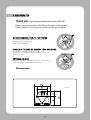
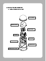
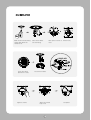
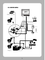
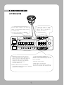
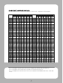
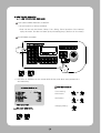
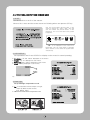
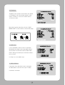
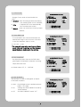
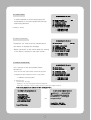
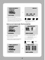
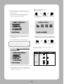
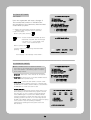
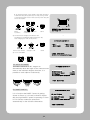
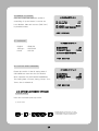
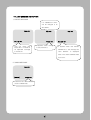
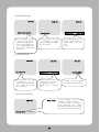
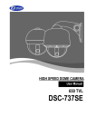
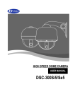
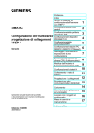
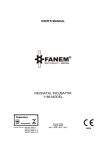
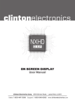
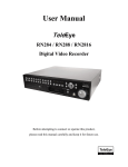
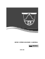
MINI SPEED DOME CAMERA
MINI SPEED DOME CAMERA
User MANUAL
GSD-200
TABLE OF CONTENTS
1. CATION ------------------------------------------------------- 3
2. INTRODUCTION OF PRODUCT
-------------------------------5
1). DESCRIPTION AND FEATURES -----------------------------5
2). INSTALLING AND CONNECTING ---------------------------- 6
2-1.
NAME AND FUNCTION OF EACH PART -------------------6
2-2. INSTALLATION
2-3.
--------------------------------------7
CONNECTION DIAGRAM --------------------------------8
3. DIRECTIONS FOR USE -----------------------------------------9
1). DIP SWITCH SETTING ---------------------------------------9
2). HOW TO CHANGE PROTOCOL -------------------------------10
3). HOW TO SET ADDRESS DIP SWITCHES ----------------------11
4). HOW TO USE OSD MENU
4-1.
----------------------------------12
HOW TO CONTROL OSD MENU --------------------------12
4-2. FUNCTIONAL DESCRIPTIONS ON EACH MENU ------------13
4-3.
SETTING FUNCTIONS BY KEYBOARD---------------------23
4-4. OSD MESSAGE DESCRIPTION ---------------------------27
4. TROUBLE SHOOTING ------------------------------------------29
5. DIMENSIONS & ASSEMBLES------------------------------------30
6. CONFIGURALTION ---------------------------------------------31
7. SPECIFICATIONS ----------------------------------------------33
1. CAUTION
Thank you for purchasing mini speed dome camera GMS-200.
Please operate the product after being fully aware of the manual.
Pease contact us if you have any queries or face any problems.
DO NOT CONTROL PAN, TILT BY FORCE
Do not move the inside Pan/Tilt motor by force
after removing dome cover.
It can cause damages.
HANDLE WITH CARE OF CAMERA LENS AND DOME
Be careful of handle with dome cover
Please use a soft fabric due to a scratch when you
clean the cover.
EXTERNAL SHOCK
Damages can be occurred through the carelessness
Or shock when you take out the module.
Dimensions
UNIT:mm
CAUTION IN USE.
Do not disassemble the unit and put alien substances in the unit.
It can cause troubles.
Ensure power switch-off before the installation.
Ensure power switch-off and check the voltage the camera before the installation.
Do not give the unit a shock and an operation.
Giving a strong shock or an excessive power on the button, terminal can cause troubles.
This product has been designed and manufactured in accordance with the harmonized European
standards, following the provisions of the below stated directives.
Electromagnetic Compatibility Directive 89/336/EEC(EN61000-3-2:1995, EN61000-3-3:1995,
EN50081-1:1992, EN50082-1:1997)
This devise complies with part 15 of the fcc rules operation is subject to the following two
conditions: (1) This device may not cause harmful interference and (2) This device must accept
any interference received including interference that may cause undesired operation
2. INSTRUCTION OF PRODUCT
1) DESCRIPTION AND FEATURES
- Description This camera has been designed elegantly for buildings, department stores that need to be
in harmony with the interior as a high speed dome camera, including various observation
functions. It moreover is effective for true Day & Night.
- Features High magnification zoom lens
250 Preset positions
Max 100 times zoom
A maximum of 250 preset positions can be
(optical x10 zoom, digital x10 zoom)
programmed. The preset function enables to set
where you want on monitor at any time.
Horizontal resolution min. 520 TVL
4ch alarm inputs
Color: min.520 TVL, B/W: min.570 TVL
horizontal resolution
It can be directly connected to sensor and used
with presets owing to built-in
Low light and Day & Night
4-channel
sensor input terminals.
It can be also operated together with other
The result of improving sensitivity
equipment owing to built-in alarm output.
0.0007Lux (DSS Control)
Auto Tilt move
ICR Day & Night allows the filter to change
B/W mode (0.1 Lux) in the night.
The unit can track the object moving automatically
until 180° in vertical.
Additional functions
OSD (On Screen Display)
PTZ trace:
Memorize P/T/Z move for 120 seconds then
Provides character information displayed on the
operate the registered trace.
monitor, such as the camera ID address,
camera name, preset number, sequence status,
Auto swing:
and sets various functions of camera easily on
Repeat pan and tilt between two preset
the OSD menu screen.
positions.
Privacy Zones
Group:
12 Preset positions are chained in one Group.
For the privacy, it can be programmed for
(Max 12 Groups available)
masking zone up to 4 locations on the
OSD menu screen.
Tour:
Max 12 Groups are bound.
410k Pixel CCD CAMERA
SONY CCD chip with high resolution and low
illumination condition.
Audio out (Option)
Built-in mono microphone without Amplifier.
2). INSTALLATION AND CONNECTION
2-1. NAME AND FUNCTION OF EACH PART
104 ¢ BUBBLE
CAMERA COVER
CAMERA BASE
P/T BASE
MAIN BASE
BOTTOM COVER
CAMERA BODY
CAMERA BODY COVER
2-2. INSTALLATION
Make 4 holes after attaching
ceiling guide where the
camera is set.
Set up DIP switch
(Reference to XXP)
Tighten 4 screws.
Take out the cables
from the ceiling.
Take apart 4 bands of camera body
cover
Connect with cables.
Attach the camera
body cover
Completion
2-3. CONNECTION DIAGRAM
AC24V/500mA(GMS-200iS)
DC12V/1A
(GMS-200S)
VIDEO IN
AUDIO IN
Violet(N/O)
Gray(COM)
Black(GND)
Brown(CH1)
Red(CH2)
Yellow(CH3)
Green(CH4)
CAMERA 1~128
DC JACK
RS-485
Sensor 1
4 ALARM INPUT
VIDEO INPUT
AUDIO
CAMERA 129
~CAMERA 255
Sensor 4
3. DIRECTIONS FOR USE
1) DIP SWITCH SETTING
Set the camera numbers in the state of
ADDR, set communication speed, protocol
in the state of INIT.
-This part is each address of
It shows the status of Power
On/Off. Green LED is On while
power is alive. In the status of
operation, red LED is off.
camera.-
-TERMINALATION RESISTOR (DIP SW NO1)
~Turn the last camera on the data line as a
switch to turn on/off the terminal resistor on.
Turn the DIP SW of some of the farthest
cameras on in the case of the data lines
distributed to several directions.
* The first default is off.
-ADDRESS/ INITIAL SELECT (DIP SW NO3)
~Set ADDRESS DIP SW in the status of ADDRESS
(*Reference to next page*)
(.*** The first default is ADDRESS.**)
-Set the communication speed and Protocol
(Demand for the technical inquiry) up in the
state of the INITAIL.
-Select PAL / NTSC system.
-POWER ON/OFF (DIP SW NO4)
Set DIP SW only in the status of Power off.
Then turn on the power after setting DIP SW.
2) HOW TO CHANGE PROTOCOL
Set up this part.
The switch that selects Protocol.
The switch that selects Baud Rate.
.
Change No.3 at S2 to INIT if want to change Protocol.
①
②
③
④
⑤
Please make Power off.
Switch Protocol that wants to change on as above table.
Make Power on, then set Protocol and Baud rate are appealed.
Make Power off, if every setting is right. Then it is done.
Change No.3 of S2 to ADDR before Power on, then make Power on after setting the
address of the camera.
⑥ Try it again with the information as above the table, if something is wrong.
3) HOW TO SET ADDRESS DIP SWITCHES
Use DIP switches No.1 to No.8 for address, it can be set 1 program to 255 program.
DIP SWITCH (HEX)
RX NO
RX NO
1
1
ON
OFF OFF OFF OFF OFF OFF
33
ON OFF OFF OFF OFF ON
OFF
2
OFF
ON
OFF OFF OFF OFF OFF
34
OFF ON OFF OFF OFF ON
OFF
3
ON
ON
OFF OFF OFF OFF OFF
35
ON
ON OFF OFF OFF ON
OFF
4
OFF
OFF
ON
OFF OFF OFF OFF
36
OFF OFF ON OFF OFF ON
OFF
5
ON
OFF
ON
OFF OFF OFF OFF
37
ON OFF ON OFF OFF ON
OFF
6
OFF
ON
ON
OFF OFF OFF OFF
38
OFF ON
ON OFF OFF ON
OFF
7
ON
ON
ON
OFF OFF OFF OFF
39
ON
ON OFF OFF ON
OFF
8
OFF
OFF OFF
ON
OFF OFF OFF
40
OFF OFF OFF ON OFF ON
OFF
9
ON
OFF OFF
ON
OFF OFF OFF
41
ON OFF OFF ON OFF ON
OFF
10
OFF
ON
OFF
ON
OFF OFF OFF
42
OFF ON OFF ON OFF ON
OFF
11
ON
ON
OFF
ON
OFF OFF OFF
43
ON
OFF
12
OFF
OFF
ON
ON
OFF OFF OFF
44
OFF OFF ON
ON OFF ON
OFF
13
ON
OFF
ON
ON
OFF OFF OFF
45
ON OFF ON
ON OFF ON
OFF
14
OFF
ON
ON
ON
OFF OFF OFF
46
OFF ON
ON
ON OFF ON
OFF
ON
ON
ON
ON OFF ON
2
3
4
5
6
7
(DEC)
DIP SWITCH (HEX)
1
2
ON
3
4
5
6
ON OFF ON OFF ON
15
ON
ON
OFF OFF OFF
47
ON
16
OFF
OFF OFF OFF
ON
OFF OFF
48
OFF OFF OFF OFF ON
ON
OFF
17
ON
OFF OFF OFF
ON
OFF OFF
49
ON OFF OFF OFF ON
ON
OFF
18
OFF
ON
OFF OFF
ON
OFF OFF
50
OFF ON OFF OFF ON
ON
OFF
19
ON
ON
OFF OFF
ON
OFF OFF
51
ON
ON OFF OFF ON
ON
OFF
20
OFF
OFF
ON
OFF
ON
OFF OFF
52
OFF OFF ON OFF ON
ON
OFF
21
ON
OFF
ON
OFF
ON
OFF OFF
53
ON OFF ON OFF ON
ON
OFF
22
OFF
ON
ON
OFF
ON
OFF OFF
54
OFF ON
ON OFF ON
ON
OFF
23
ON
ON
ON
OFF
ON
OFF OFF
55
ON
ON OFF ON
ON
OFF
24
OFF
OFF OFF
ON
ON
OFF OFF
56
OFF OFF OFF ON
ON
ON
OFF
25
ON
OFF OFF
ON
ON
OFF OFF
57
ON OFF OFF ON
ON
ON
OFF
26
OFF
ON
OFF
ON
ON
OFF OFF
58
OFF ON OFF ON
ON
ON
OFF
27
ON
ON
OFF
ON
ON
OFF OFF
59
ON
ON
ON
OFF
28
OFF
OFF
ON
ON
ON
OFF OFF
60
OFF OFF ON
ON
ON
ON
OFF
29
ON
OFF
ON
ON
ON
OFF OFF
61
ON OFF ON
ON
ON
ON
OFF
30
OFF
ON
ON
ON
ON
OFF OFF
62
OFF ON
ON
ON
ON
ON
OFF
31
ON
ON
ON
ON
ON
OFF OFF
63
ON
ON
ON
ON
ON
OFF
32
OFF
OFF OFF OFF OFF
ON
64
OFF OFF OFF OFF OFF OFF
ON
OFF
ON
7
ON
ON OFF ON
ON
OFF
-No.1 is changed to No.64 and the last No.64 is changed No.128 when No.7 DIP SW is on.
-No.1 is changed to No.129 when No.7 DIP SW is off and No.8 DIP SW is on.
-No.1 is changed to No.193 and user can set up to maximum 255 ADDRESS when No.7, 8 DIP SW
are on.
4) HOW TO USE OSD MENU
4-1. HOW TO CONTROL OSD MENU
OSD (ON SCREEN DISPLAY) CONTROL
It is the function to call up the Menu
*User can not only set Preset, Group, Tour, Swing, Trace functions of the camera
up by the menu, but also set them up by shortening keys. (Refer to 4-3 content)
ACCESSING OSD MENU
①
②
1) The menu is displayed on the screen with the key tone when user presses No.1
and menu key.
<< CAMERA SETUP p1 >>
1.
2.
3.
4.
5.
6.
7.
8.
ID Set
OSD Display
Back Light
AGC level
Shutter speed
Sharpness level
Brightness
Flickerless
:
:
Press F/F Key
ID + Status
: Off
: Low
: Auto
: 003
: 005
: Manual
-NEXT MENU PAGE
RELEASE OSD MENU
OSD Menu Control
Cursor Moving
:
Feed Letters
:
Select Menu
:
Changing Setting :
4-2. FUNCTIONAL DESCRIPTIONS ON EACH MENU
1. ID SET
It is the function to set ID of the camera.
Move to No.1 menu and the screen moves as following when user presses F/F key.
User can choose letters that they want, if user
control a joystick up / down / right / left, and
user can reselect the previous letters, if user
presses Z/I, Z/O or turn the head of the joystick
to right/left.
" ● "” is not displayed on the screen as a
blank letter, user can input letters in Japanese
and in Chinese if user moves the joystick down
continuously.
2. OSD DISPLAY
Set up whether sets ID and STATUS to display on the screen in normal operating.
►
►
►
►
ID + Status: ‘ID’ and ‘Status’ displayed on the screen
ID only: Only ‘ID’ displayed on the screen.
Status only: Only ‘Status’ displayed on the screen
All off: Nothing displayed on the screen.
<< CAMERA SETUP p1 >>
1.
2.
3.
4.
5.
6.
7.
8.
ID Set
OSD Display
Back Light
AGC level
Shutter speed
Sharpness level
Brightness
Flickerless
:
:
Press F/F Key
ID + Status
: Off
: Low
: Auto
: 003
: 005
: Manual
Ex).
-NEXT MENU PAGE
3. Back Light
Set up backlight compensation mode.
► On: It compensates a dark subject to a light
object by BACK LIGHT function.
(Low, Middle, High)
► Off: Release BACK LIGHT compensation mode
<< CAMERA SETUP p1 >>
1.
2.
3.
4.
5.
6.
7.
8.
ID Set
OSD Display
Back Light
AGC level
Shutter speed
Sharpness level
Brightness
Flickerless
-NEXT MENU PAGE
:
:
Press F/F Key
ID + Status
: Off
: Low
: Auto
: 003
: 005
: Manual
4. AGC level
AGC(Automatic Gain Control)- It adjusts the
amount of video amplification to maintain a
full 1-volt peak-to-peak video signal output
automatically.
<< CAMERA SETUP p1 >>
1.
2.
3.
4.
5.
6.
7.
8.
ID Set
OSD Display
Back Light
AGC level
Shutter speed
Sharpness level
Brightness
Flickerless
:
Press F/F Key
ID + Status
: Off
: Low
: Auto
: 003
: 005
: Manual
:
► Range: Low, Middle, High
-NEXT MENU PAGE
5. Shutter speed
<< CAMERA SETUP p1 >>
As a setting shutter speed mode, it can be
distinguished a fast moving subject easily by
means of shutter speed up.
* The illumination of the camera decreases if shutter
speed is getting up.
* The default value is ‘AUTO’
* It can be worked in the status of Flickerless ‘off’.
1.
2.
3.
4.
5.
6.
7.
8.
ID Set
OSD Display
Back Light
AGC level
Shutter speed
Sharpness level
Brightness
Flickerless
:
Press F/F Key
ID + Status
: Off
: Low
: Auto
: 003
: 005
: Manual
:
-NEXT MENU PAGE
Range: AUTO, 1/120, 1/250, 1/500,....1/60000
6. Sharpness level
<< CAMERA SETUP p1 >>
Compensation of the shape of a object.
► Rage: 0 ~ 10 , Default value : 03
1.
2.
3.
4.
5.
6.
7.
8.
ID Set
OSD Display
Back Light
AGC level
Shutter speed
Sharpness level
Brightness
Flickerless
:
Press F/F Key
ID + Status
: Off
: Low
: Auto
: 003
: 005
: Manual
:
-NEXT MENU PAGE
7. Brightness
Control brightness of the screen.
► Range: 0 ~ 99 , Default value: 50
<< CAMERA SETUP p1 >>
1.
2.
3.
4.
5.
6.
7.
8.
ID Set
OSD Display
Back Light
AGC level
Shutter speed
Sharpness level
Brightness
Flickerless
-NEXT MENU PAGE
:
:
Press F/F Key
ID + Status
: Off
: Low
: Auto
: 003
: 005
: Manual
8. Flickerless
Tremble on the screen is removed in the status
of Flickerless ‘ON’, the shutter speed, at the
same, is Fixed in 1/120 sec in NTSC and in
1/100 sec in PAL.
<< CAMERA SETUP p1 >>
1.
2.
3.
4.
5.
6.
7.
8.
ID Set
OSD Display
Back Light
AGC level
Shutter speed
Sharpness level
Brightness
Flickerless
:
:
Press F/F Key
ID + Status
: Off
: Low
: Auto
: 003
: 005
: Manual
-NEXT MENU PAGE
Move the joystick down then choose “NEXT
MENU PAGE” on the screen to move next page.
<< CAMERA SETUP p1 >>
1.
2.
3.
4.
5.
6.
7.
8.
ID Set
OSD Display
Back Light
AGC level
Shutter speed
Sharpness level
Brightness
Flickerless
:
:
Press F/F Key
ID + Status
: Off
: Low
: Auto
: 003
: 005
: Manual
-NEXT MENU PAGE
9. SSNR level
It can remarkably reduce noise of minimum
illumination by super noise removable technique and also file size becomes smaller while
DVR is being recorded by the effective reducetion of noise.
<< CAMERA SETUP p2 >>
9. SSNR level
10. White balance
11. Focus mode
12. Zoom MAX Limit
13. DSS CONTROL
14. DAY & NIGHT
: Middle
: Outdoor
: Oneshot
: x20
: Off
: Auto
- PREV MENU PAGE
- NEXT MENU PAGE
► Range: Off, Low, Middle, High
10. White balance
It prevents from that white color is changed
as illumination, user can set it up in 2 ways.
<< CAMERA SETUP p2 >>
9. SSNR level
10. White balance
11. Focus mode
12. Zoom MAX Limit
13. DSS CONTROL
14. DAY & NIGHT
► INDOOR, OUTDOOR
- PREV MENU PAGE
- NEXT MENU PAGE
: Middle
: Outdoor
: Oneshot
: x20
: Off
: Auto
11. Focus mode
Change Focus mode to hand-worked or
Auto.
► OneShot : Auto Focusing mode works during
non-working after zoom is worked..
► Auto
: It adjusts the focus automatically
As it monitors the screen.
► Manual : User can control the focus by handworked..
<< CAMERA SETUP p2 >>
9. SSNR level
10. White balance
11. Focus mode
12. Zoom MAX Limit
13. DSS CONTROL
14. DAY & NIGHT
: Middle
: Outdoor
: Oneshot
: x20
: Off
: Auto
- PREV MENU PAGE
- NEXT MENU PAGE
12. Zoom MAX Limit
<< CAMERA SETUP p2 >>
It is used when user corrects and limits the
extensional range of the focus as a function
to set the maximum value of zoom.
► Off, x20 ~ x100
The camera is reset when user is out of Menu
mode after end the setting, and the changed
magnification is registered in the camera.
13. DSS CONTROL
An object becomes clear as the field value
gets higher in illumination, whereas a moving
object becomes dim.
9. SSNR level
10. White balance
11. Focus mode
12. Zoom MAX Limit
13. DSS CONTROL
14. DAY & NIGHT
: Middle
: Outdoor
: Oneshot
: x20
: Off
: Auto
- PREV MENU PAGE
- NEXT MENU PAGE
<< CAMERA SETUP p2 >>
9. SSNR level
10. White balance
11. Focus mode
12. Zoom MAX Limit
13. DSS CONTROL
14. DAY & NIGHT
: Middle
: Outdoor
: Oneshot
: x20
: Off
: Auto
► Default value: Off, 2 ~ 128 field
- PREV MENU PAGE
- NEXT MENU PAGE
14. DAY & NIGHT
The function is used to distinguish an object
In the dark condition.
► Auto : Day & Night mode is worked automatically, if it is dark.
► On : Change into DAY & NIGHTY mode by
hand-worked
► Off : Set DAY & NIGHTY mode ‘Off’
<< CAMERA SETUP p2 >>
9. SSNR level
10. White balance
11. Focus mode
12. Zoom MAX Limit
13. DSS CONTROL
14. DAY & NIGHT
- PREV MENU PAGE
- NEXT MENU PAGE
: Middle
: Outdoor
: Oneshot
: x20
: Off
: Auto
15. Select Alarm
<< CAMERA SETUP p3>>
15.
16.
17.
18.
19.
20.
21.
It selects whether it moves the preset point
automatically or it moves by MOTION function
when being alarmed.
► Motion, Sensor
Select Alarm
: Sensor
Motion Detection
: Off
PRESET & RUN PAGE
TRACE SET PAGE
ALARM CH ON/OFF
ALARM PRESET SET PAGE
PRIVACY ZONE SET PAGE
- PREV MENU PAGE
- NEXT MENU PAGE
16. Motion Detection
<< CAMERA SETUP p3 >>
15.
16.
17.
18.
19.
20.
21.
Set Motion ‘On’ after move the camera where
user wants. It displays the message
‘Motion Detected’ on the screen when the moving
of an object is sensed on the same screen.
Select Alarm
: Sensor
Motion Detection
: Off
PRESET & RUN PAGE
TRACE SET PAGE
ALARM CH ON/OFF
ALARM PRESET SET PAGE
PRIVACY ZONE SET PAGE
- PREV MENU PAGE
- NEXT MENU PAGE
17. PRESET & RUN PAGE
<< CAMERA SETUP p3 >>
It is a function to set and operate Preset,
15.
16.
17.
18.
19.
20.
21.
Group,Tour.
User can see the screen when moves the joystick
to Right/Left after fixing the cursor on the menu.
<< PRESET SETUP PAGE>>
Select Alarm
: Sensor
Motion Detection
: Off
PRESET & RUN PAGE
TRACE SET PAGE
ALARM CH ON/OFF
ALARM PRESET SET PAGE
PRIVACY ZONE SET PAGE
- PREV MENU PAGE
- NEXT MENU PAGE
① Preset set CH:
Set Preset No. and title.
- Preset No.: Set it by moving the joystick to Right/Left
- Preset Title: It displays “SET ID” when presses F/F key after setting Preset No.
* The setting steps are the same as “ID Set” at the part 4-2-1.
<< PRESET SET & RUN PAGE >>
-
Preset set CH : 001
Preset PTZ SET
Preset Swing SET
Group SET CH : 001
Tour SET Group
Run Function : UNDEF
RETURN MENU PAGE
Press F/F Set Mode
<< SET CH:001[PRESET:001] >>
▷▶
●!#$%&()*+`-./0123456789
:;<=>?@ABCDEFGHIJKLMNOPQ
RSTUVWXYZ[\]^_,abcdefghijkl
mnopqrstuvwxyz
Zoom In/Out , OSD Shift
Press SAVE F/F , ESC F/N
<< PRESET SET & RUN PAGE >>
-
PRESET : 001
Preset set CH : 001
Preset PTZ SET
Preset Swing SET
Group SET CH : 001
Tour SET Group
Run Function : UNDEF
RETURN MENU PAGE
▷▶
[SAVE]
Press F/F Set Mode
[DELETE]
[ESC]
F/F Save Return, F/N Select
② Preset PTZ: Set preset points.
Select the main menu with the joystick, then
press F/F key for next page. Select [SAVE] with
F/N key after setting the Preset point by using the
joystick and In/Out function, then the data is saved
if user presses F/F key, then it is moved to the
previous screen automatically from the menu.
① Set preset point
② Move to menu
③ Check
●[SAVE]: Previous screen after saving
[DELETE]: Remove
[ESC]: Cancel
*Repeat the same way after changing the number of Preset, if user set another Preset.
<< PRESET SET & RUN PAGE >>
-
Preset set CH : 001
Preset PTZ SET
Preset Swing SET
Group SET CH : 001
Tour SET Group
Run Function : UNDEF
RETURN MENU PAGE
<< SWING SETUP PAGE >>
▷▶
Press F/F Set Mode
-
P/T Swing
Start Preset
End Preset
Swing Time
Swing Speed
: Undef (TILT/PAN)
: 000 (1~250)
: 000 (1~250)
: 000 (1~127)
: 000 (1~64)
Press F/F Save, F/N(ESC)
•P/T Swing: TILT - Observe up and down,
PAN - Observe right and left
•Start Preset: Preset number of the location to be
started an observation
•End Preset: Preset number of the location to be
ended an observation
•Swing Time: Dwell time after moving
•Swing Speed: Moving speed
③ Preset Swing SET : Set Preset Swing.
Move next SWING page for the setting,
when pressing F/F key in the state of
selection of the menu.
▪ The preset must be set before the setting because
Swing is a function to repeat an auto observation
of 2 Preset points user select in Preset set
: Selection of
Up/down menu
<< PRESET SET & RUN PAGE >>
-
Preset set CH : 001
Preset PTZ SET
Preset Swing SET
Group SET CH : 001
Tour SET Group
Run Function : UNDEF
RETURN MENU PAGE
Press F/F Set Mode
: Change of
A setting
<< GROUP SET CH:01 >>
▷▶
[P]
000
000
000
000
000
000
[S]
000
000
000
000
000
000
[T]
000
000
000
000
000
000
[P]
000
000
000
000
000
000
Press F/F Save, F/N(ESC)
[S]
000
000
000
000
000
000
[T]
000
000
000
000
000
000
● [P]: Set Preset points (1~250)
● [S]: Moving speed (1~64)
● [T]: Dwell time
④ GROUP SET: User can set maximum 12 groups
Select a channel then move to next page after
pressing F/F key
• The Preset point in the Group that 12 Preset
points are set is observed repeatedly and in
order with regular speed and time.
① Set Preset
② Next setting
③ Set moving speed ④ Next setting
⑤ Set dwell time
<< PRESET SET & RUN PAGE >>
-
Preset set CH : 001
Preset PTZ SET
Preset Swing SET
Group SET CH : 001
Tour SET Group
Run Function : UNDEF
RETURN MENU PAGE
⑥ Out of menu
after saving
<< TOUR SETUP PAGE >>
T01:01
T05:00
T09:00
▷▶
Press F/F Set Mode
⑤ Tour SET Group : User can set continual Group
motion that can be put 12 Groups in 1 Tour
Move to the setting page if user presses F/F key
on this menu.
T02:00
T06:00
T10:00
T03:00
T07:00
T11:00
T04:00
T08:00
T12:00
Press F/F Save, F/N(ESC)
Set the value of “00” part of T01~T12 to Group
channel that User wants, then the setting is saved
when user is out of the menu after pressing F/F key.
▪ The Group user wants to set must be set first.
Setting is only possible when Preset is set first
in the state of setting of Swing, Group, Tour,
①Select Group
channel
②Set next
Channel
③Out of menu saving
after channel
otherwise, it displays the message “Sorry Undefined” .
⑥ Run Function: Operate one of SWING/ GROUP/
TOUR/ TRACE. (It is operated automatically after
the end of OSD menu.)
*Set / Stop order with a control keyboard without
menu on the screen.
RUN
<< PRESET SET & RUN PAGE >>
-
Preset set CH : 001
Preset PTZ SET
Preset Swing SET
Group SET CH : 001
Tour SET Group
Run Function : UNDEF
RETURN MENU PAGE
Preset
1~250 +
Swing
1(PAN)
or
▪ User can look at how to set TRACE at “18. TRACE SET PAGE”
⑦ RETURN MENU PAGE : Move to a higher menu
page when control the joystick Right/Left in the
selection of this menu.
+
or
+
or
2(TILT)
Group
Press F/F Set Mode
STOP
Tour
1~12
or
18. TRACE SET PAGE
Set TRACE.
User can regenerate and save a change of
The unrestricted location of ZOOM In/Out
and a position of the camera by hand-worked
control with a joystick
<< CAMERA SETUP p3 >>
15.
16.
17.
18.
19.
20.
21.
Select Alarm
: Sensor
Motion Detection
: Off
PRESET & RUN PAGE
TRACE SET PAGE
ALARM CH ON/OFF
ALARM PRESET SET PAGE
PRIVACY ZONE SET PAGE
- PREV MENU PAGE
- NEXT MENU PAGE
▪ It displays the screen when moves the joystick to
Right/Left after fixing the cursor on the menu
▪ How to set TRACE.
Move to [SET] after pressing
.
Check – Control scenes that user wants by hand-
<< P/T/Z TRACE SET >>
∇
worked with a joystick after the message
“Set Trace: OO%” on the middle of the
screen. If user finishes this part
Move to [SAVE] with
It goes a higher menu after being saved data when
pressing
[SET] [SAVE]
[DELETE]
[ESC]
F/F Save Return, F/N Select
with a display of the message “Save TRACE”.
▬▬▬▬▬▬▬▬▬▬▬▬▬▬▬▬▬▬▬▬▬▬▬▬▬▬▬▬▬▬▬▬▬▬▬▬▬▬▬▬▬
19. ALARM CH ON/OFF
<< CAMERA SETUP p3 >>
■ What is ALARM function?: It operate to observe
the location of the camera which is memorized previously in the situation of the warning signal or trespassers by using a sensor.
- CH On/Off: Alarm Input – Each channel can be ON/OFF
- Alarm Relay: It can be set On or not when ALARM OUTPUT
PORT operate wrong.
15.
16.
17.
18.
19.
20.
21.
Select Alarm
: Sensor
Motion Detection
: Off
PRESET & RUN PAGE
TRACE SET PAGE
ALARM CH ON/OFF
ALARM PRESET SET PAGE
PRIVACY ZONE SET PAGE
- PREV MENU PAGE
- NEXT MENU PAGE
- Active Alarm: It selects ACTIVE OPEN or ACTIVE CLOSE
by tangency when something is wrong. It is ACTIVE when
ALARM INPUT is OPEN in ACTIVE OPEN, it is ACTIVE when
ALARM INPUT is CLOSE in ACTIVE CLOSE.
- Resume Time Set :
It can select the waiting time that the camera move to the
Place alarming to observe where wrong signal is sensed.
User can set it for 1sec to 180sec and operate GROUP,
TOUR, SWING again in a preset time. SWING, GROUP,
TOUR are operated in a preset time when user stops the
operating joystick in the case of not connecting with the
ALARM. Press SWING, GROUP, TOUR keys without stopping
of the joystick to stop the operating completely.
(*Stopping the operating with the joystick affects the
SET function.)
<< ALARM CHANNEL ON/OFF >>
- CH1
- CH3
:Off
:Off
-CH2
-CH4
- Alarm Relay
- Active Alarm
- Resume timeset
- RETURN MENU PAGE
:Off
:Off
:Off
:Close
:Off
20. ALARM PRESET SET PAGE
• The camera can move to a preset point automatically when
something is wrong in each ALRAM CHANNEL.
• Set a preset point firstly to move if anything wrong, then
use that sets the preset number into each ALARM
CHANNEL.
<< CAMERA SETUP p3>>
15.
16.
17.
18.
19.
20.
21.
• PRESET is out of connecting in ALARM CHANNEL No.“0”.
Select Alarm
: Sensor
Motion Detection
: Off
PRESET & RUN PAGE
TRACE SET PAGE
ALARM CH ON/OFF
ALARM PRESET SET PAGE
PRIVACY ZONE SET PAGE
- PREV MENU PAGE
- NEXT MENU PAGE
• User can select PRESET number 1 to 250 and set it.
• Home Position Preset
Master user can observe a previous area automatically
when another user move the camera’s sight to other area.
(It is possible 1 to 250)
▪ Home Position Time
It sets waiting time of Home Position Preset.
The camera moves to observe a preset area in a set time
Master set after observing another area, in the operating of
Home Position Time. (It is possible 1 to 180sec. Set a
concurrent control of Home Position Preset and Home
Position Time for using this function.)
As above the setting menu, ALARM setting MENU can
not set only in CAMERA SET MENU MODE, but also a
keyboard in direct.
<< ALARM PRESET SET >>
∇
- CH
: 001 - CH
: 002
- CH
: 003 - CH
: 004
- Home Position Preset : 001~250
- Home Position Time : OFF/001~180
- RETURN MENU PAGE
21. PRIVACY ZONE SET PAGE
<< CAMERA SETUP p3 >>
Up to 4 privacy zones can be configured for
the protection of privacy.
▪ How to set.
In <PRIVACY ZONE SET>, move to the channel that
user wants by joystick and press F/F key, then the screen
will be turned over.
①
15.
16.
17.
18.
19.
20.
21.
Select Alarm
: Sensor
Motion Detection
: Off
PRESET & RUN PAGE
TRACE SET PAGE
ALARM CH ON/OFF
ALARM PRESET SET PAGE
PRIVACY ZONE SET PAGE
- PREV MENU PAGE
- NEXT MENU PAGE
: Select channels
∇
②
: Select Set/On/Off/Del
<< PRIVACY ZONE SET >>
- CH1 : BLANK
- CH3 : BLANK
Set : Set a new privacy
Off : Hide privacy areas
- CH2 : BLANK
- CH3 : BLANK
On : Display privacy areas
Del : Delete privacy areas
Display only “Set” on channel where PRIVACY ZONE Is not set.
③
: check, next page
- PREV MENU PAGE
ENTER (F/F), Select L/R, Change
④ fix the black square on the middle of area that user wants
to hide with using the joystick (Z/I, Z/O Key), then go back
to the previous page on the screen (F/F Key) after fixing the
size of the square.
ENTER(F/F),Save ESC(F/N),ESC
Set Privacy : 01
Select
a position
Extension / Reduction
of the BOX
Check
⑤ The Channel is changed from Blank to OFF.
The black box is displayed when pressing F/F key
after changing it to ‘ON’ as left picture.
∇
<< PRIVACY ZONE SET >>
- CH1 : ON
- CH3 : BLANK
Move to the channel
Change to ‘ON’
- CH2 : BLANK
- CH4 : BLANK
Check
⑥ Out of OSD MENU
- PREV MENU PAGE
ENTER ( F / F ), Select L/R,Change
22. AUTO TILT MOVE
The PAN is turned in a 180° degree arc
Automatically when the angle of the camera moves
down to the maximum degree, therefore, it is
possible to track objects continuously.
<< CAMERA SETUP p4 >>
22.
23.
24.
25.
26.
Auto Tilt Move
: Off
Smart pan Tilt
: On
Manual P/T Speed
: Medium
Language
: English
FACTORY RESET WARNING!
-PREV MENU PAGE
23. SMART PANTILT
It is a function that PANTILT speed is getting
slower as Zoom in. It is hard to observe objects
with the high PANTILT speed in operating of Zoom
In This function makes the speed less
automatically for the effective observation.
<< CAMERA SETUP p4 >>
22.
23.
24.
25.
26.
Auto Tilt Move
: Off
Smart pan Tilt
: On
Manual P/T Speed
: Medium
Language
: English
FACTORY RESET WARNING!
-PREV MENU PAGE
24. MANUAL P/T SPEED
<< CAMERA SETUP p4 >>
User can control the maximum speed in
controlling of up and down. It can be set
Low, Medium, Max and one turn (360°/sec)
is possible in Max.
22.
23.
24.
25.
26.
Auto Tilt Move
: Off
Smart pan Tilt
: On
Manual P/T Speed
: Medium
Language
: English
FACTORY RESET WARNING!
-PREV MENU PAGE
25. LANGUAGE
<< CAMERA SETUP p4 >>
English
PortuguPolish
: ENGLISH
: PORTUGU
: POLISH
22.
23.
24.
25.
26.
Auto Tilt Move
: Off
Smart pan Tilt
: On
Manual P/T Speed
: Medium
Language
: English
FACTORY RESET WARNING!
-PREV MENU PAGE
26. FACTORY RESET WARNING
<< CAMERA SETUP p4 >>
Please be careful of that all setting data of
OSD MENU are reset into the first default
when operates FACTORY RESET WARNING.
The setting data of Preset, Swing, Group, Tour,
22.
23.
24.
25.
26.
Auto Tilt Move
: Off
Smart pan Tilt
: On
Manual P/T Speed
: Medium
Language
: English
FACTORY RESET WARNING!
Trace, also is deleted all.
-PREV MENU PAGE
4-3. SETTING FUNCTIONS BY KEYBOARD
1. Preset setting
User can set Preset point up to 250.
① Preset Input
Preset setting can be set 1 to 250
sequentially after moves the camera
to the place to will be memorized
② Preset Move
Move to the fixed point if user presses P-SET
button after pressing Preset number that user
wants.
.
▬▬▬▬▬▬▬▬▬▬▬▬▬▬▬▬▬▬▬▬▬▬▬▬▬▬▬▬▬▬▬▬▬▬▬▬▬▬▬▬▬▬▬▬▬▬▬▬▬▬▬▬▬
③ Delete a separate Preset
Go on in order as follow when the sound is
heard in 3 sec after pressing
Ex) Delete 5th Preset
.
(waiting for 3 sec)
3 sec)
▬▬▬▬▬▬▬▬▬▬▬▬▬▬▬▬▬▬▬▬▬▬▬▬▬▬▬▬▬▬▬▬▬▬▬▬▬▬▬▬▬▬▬▬▬▬▬▬▬▬▬▬▬
④ Delete all Preset
Go on in order as follow when the sound is
heard in 3 sec after pressing
(waiting for 3 sec)
▬▬▬▬▬▬▬▬▬▬▬▬▬▬▬▬▬▬▬▬▬▬▬▬▬▬▬▬▬▬▬▬▬▬▬▬▬▬▬▬▬▬▬▬▬▬▬▬▬▬▬▬▬▬
2. Swing setting
① Swing Input
Set the dwell time. (1~127sec)
Set the move speed (1~64 steps)
▬▬▬▬▬▬▬▬▬▬▬▬▬▬▬▬▬▬▬▬▬▬▬▬▬▬▬▬▬▬▬▬▬▬▬▬▬▬▬▬▬▬▬▬▬▬▬▬▬▬▬▬▬
② Swing setting
③ End Swing
(Run Pan)
(Run Tilt)
▬▬▬▬▬▬▬▬▬▬▬▬▬▬▬▬▬▬▬▬▬▬▬▬▬▬▬▬▬▬▬▬▬▬▬▬▬▬▬▬▬▬▬▬▬▬▬▬▬▬▬▬▬
3. Group setting
① Start Group setting mode
Set Preset No. again in continual input.
Set a GROUP again from the first after ending with
, , if user wants to
finish Preset input in one Group to input another Group.
② Run Group
③ Stop Group
▬▬▬▬▬▬▬▬▬▬▬▬▬▬▬▬▬▬▬▬▬▬▬▬▬▬▬▬▬▬▬▬▬▬▬▬▬▬▬▬▬▬▬▬▬▬▬▬▬▬▬▬▬
4. Tour setting
① Tour set mode
② Start / End Tour
③ Delete Tour
▬▬▬▬▬▬▬▬▬▬▬▬▬▬▬▬▬▬▬▬▬▬▬▬▬▬▬▬▬▬▬▬▬▬▬▬▬▬▬▬▬▬▬▬▬▬▬▬▬▬▬▬▬
5. Spiral Function
It is a function to observe objects automatically in the spiral direction.
① Spiral On
② Off
6. PTZ Trace
It memorizes P/T/Z motions for 200sec then operates them at the same Trace.
① Start / End Trace
② Off
▬▬▬▬▬▬▬▬▬▬▬▬▬▬▬▬▬▬▬▬▬▬▬▬▬▬▬▬▬▬▬▬▬▬▬▬▬▬▬▬▬▬▬▬▬▬▬▬▬▬▬▬▬
② Set Trace
③ Delete Trace
4-4. OSD MESSAGE DESCRIPTION
1. PRESET MESSAGE
It is CAMERA ID and it
can be changed in ID
SET MODE.
CAM-001
Set PST 001
CAM-001
PRESET 001
User can check that
Preset No.1 is saved as
an appeared message
in Preset set
It appears when moving
to the preset No.1
CAM-001
Clear PST 001
It appears when user deletes
PRESET No.1. The message ‘All
clear
PRESET’
is
displayed
when user delete PRESER data
all at once.
2. SWING MESSAGE
CAM-001
[SWING]
PRESET:001
It shows that is RUN SWING
mode in SWING Run.
3. GROUP MESSAGE
CAM-001
GP:01 P002,T001,S64
As the message in the time
of operation of GROUP SET,
“GP:01” means group No.1,
“P002” means PRESET No.2,
“T001” means waiting time is
1sec and “S64” means move
speed is 64
CAM-001
Save Group 01
CAM-001
[GROUP: 01]
As the message in the time
of completion of GROUP
SET, it is displayed. GROUP
No.1 was saved.
.
PRESET:001
It is displayed in the time of
operation of GROUP RUN, it
shows GROUP No.1 will
move
to No.1
4. TOUR MESSAGE
CAM-001
Set Tour GP:01
CAM-001
[TOUR&GP:01]
As the message in the time
of operation of Tour set,
“GP:01” means GROUP No.1
and it shows that GROUP
No.1 was saved.
PRESET:001
As the message in the time
of operation of Tour RUN, it
will show that moving to
PRESET No.1 in GRIOUP
No.1.
CAM-001
Clear tour&GRP
It shows the data in GROUP
and TOUR saved was deleted.
5. Spiral SEQ MESSAGE
CAM-001
Set Tour GP:01
-RUN SPIRAL : It is the Message in the time of
operation of SPIRAL SEQUENCE.
It observe all area of an object in
three
dimensions
that
SPIRAL
SEQUENCE CAMERA moves to upper
then down slowly in a spiral direction.
4. TROUBLE SHOOTING
CAUTION IN USE
• Make sure that turn the power switch off before installation.
• Avoid the places where is the high/low temperature and humid.
• Use a power supply of AC24 / 1.5A output
• Please be careful of that you connect respective wires without mismatching in installation.
• Supply to power sources after checking the state of insulation of cables which is
connected to the exterior
• Please keep the product from a strong shock or vibration which is the cause of troubles.
Checking in under using
Check the product as following, if something is wrong in installation or using.
TROUBLE SHOOTING
Power is not turned on.
CHECK POINT
Does the electric power supply into the
product well?
MEASURE
Check the POWER LED is “ON” at the BOTTOM
COVER.
Check the status of DATA CABLE, if it is not lit.
In operating, does the LED beside
POWER SW light on red?
Does not work in Power On.
Check ADDRESS and DIP SW of
communication speed setting, if it is not lit.
Have you selected to RS485 or RS422
right?
Check the status of OPTION DIP SW No.2
Poor condition of PAN/TILT
Have you turned the ending terminal
register ‘ON’?
Turn ‘ON’ the ending terminal register of the
camera which is set in farthest away.
A image is not clear or black
lines are displayed on the
screen.
Is the power adapter AC24V, 1.5A over?
Exchange the adapter to for an adapter which
has higher current.
The message ‘P/T POSITION
Is the camera pressed by something
ERROR’ is displayed
heavy or put it between others?
continuously.
The message ‘SORRY NOT
MEMORY’ is displayed
continuously.
ALARM RELAY is not
changed to ‘ON’ in the state
of being alarmed.
In abnormal condition, even
if the sensor is well.
PRESET point is different or
out of moving when the
ALARM occurs. The warning
does not work from the
keyboard when the ARLAM
occurs.
Check that a rotation of the camera’s body
works smoothly and remove a object that
hinders the operation of the camera.
Have you set the related functions?
Please refer to the manual book and setting the
function you want.
Have you set the ALARM RELAY ‘ON’ in
the SET MODE?
Make sure ALARM RELAY ‘ON’ in the SET
MODE.
Is it correct ALARM ACTIVE setting status
and the sensor is either opened or
closed?
Fit ALARM ACTIVE MODE setting with the
connection of the SENDOR in the SET
MODE.(It means either sensor is opened or
closed)
Have you set ALARM PRESET in
the SET MODE?
Check the status of the ALARM PRESET
setting in the SET MODE.
Have you used the exclusive control
keyboard?
The warning is only reacted to the
exclusive control keyboard.
YES.
Make sure ALARM “ON” of the camera.
5. ASSEMBLES
measurement
Mount assemble
It can be connected with
bracket by using mount.
unit : mm
① Connect MOUNT with Wall bracket
② Fix 4 screws.
④ Completion
③ Connect Camera body cover.
PRODUCT STRUCTURE
▪ SUB KEYBOARD SETTING
1
2
3
255
GMS-200
MONITOR
MONITOR
JUNKTION BOX
DVR
(P/T CONTROL)
JUNKTION BOX
GSS-200
CONTROL KEYBOARD
(MAIN)
CONTROL KEYBOARD
(SUB8)
OR
: Control line
: Video line
GSS-5000
▪ SETTING ONE KEYBOARD
GSS-200
GSS-5000
: Control line
: Video line
7. SPECIFICATION
MODEL
Signal system
Image sensor
Effective pixels
Horizontal resolution
GSD-200
NTSC
PAL
410K Pixel, 1/4 " SONY Super HAD CCD
768(H) X 494(V),
752(H) X 582(V),
More than 500 TVL
B/W 570 TVL
Lens
10x Optical zoom, f=3.3 - 33mm, F1.8
Digital zoom
10x (Total zoom 100x)
Angle of view
Approx 51.2° (Wide) , Approx 5.58° (Tele)
Minimum illumination
0.7Lux , 0.02Lux(D&N) , 50IRE
Luminance S/N ratio
More than 50dB
Video output
1 Vp-p Composite video out 75Ω
Focus mode
Auto / Manual / Oneshot
SSNR
Off / Low / Middle / High
Back Light
Off / Low / Middle / High
Shutter speed
Auto / 1/128 ~ 1/120,000 sec
Sharpness control
Level (0 – 10)
Motion Detection
On/Off
Alarm in/out
4 Inputs / 1 Relay Output
Pan/Tilt angle
360° Endless / 92°
Pan speed
0.1° ~ 240°/sec (64 Levels)
Preset point
250 Presets
Preset Speed
Max 360°/sec (64 Levels)
Privacy zones masking
4 Zones
Operating temperature
-10°C ~ 50°C (-14°F ~ -122°F)
Communiction system
RS-485 / 422
OSD
Built-in
Operating humidity
Less than 90%RH
Dimensions
151.4 mm(Diameter) x 138(Height) mm
Weight
About 0.5Kg
Construction
PC body , Clear vandal bubble (PC)
Power consumption
6W
Power supply
AC24V / 500mA , DC12V / 1A