1
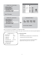
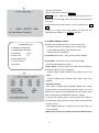
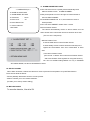
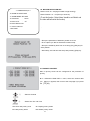
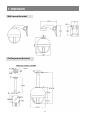
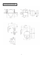
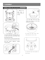
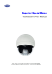
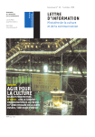
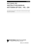
HIGH SPEED DOME CAMERA USER MANUAL DSC-300Si5/Se5 2 Table of contents 1. CAUTION -------------------------------------------------------------------------------- 2 2. INTRODUCTION OF PRODUCT 4 1). DESCRIPTION AND FEATURES --------------------------------------------- 4 2). INSTALLATION AND CONNECTION ---------------------------------------- 5 3. 2-1. NAME AND FUNCTION OF EACH PART ----------------------------- 5 2-2. INSTALLATION -------------------------------------------------------------- 6 2-3. BASIC CONNECTION ----------------------------------------------------- 8 2-4. CONNECTION DIAGRAM ------------------------------------------------ 9 DIRECTIONS FOR USE 11 1). DIP SWITCH SETTING ---------------------------------------------------------- 11 2). HOW TO CHANGE PROTOCOL ---------------------------------------------- 12 3). SETTING ADDRESS OF DIP SWITCHES ---------------------------------- 13 4). HOW TO USE OSD MENU ----------------------------------------------------- 14 4-1. HOW TO CONTROL OSD MENU --------------------------------------- 14 4-2. FUNCTIONAL DESCRIPTIONS ON EACH MENU ----------------- 15 4-3. FUNCTIONAL SETTING, OPERATION/DELETION THE KEYBOARD------------------------------------------------------------------4-4. OSD MESSAGE DESCRIPTION ---------------------------------------- 27 4 TROUBLE SHOOTING --------------------------------------------------------------- 32 5 DIMENSION --------------------------------------------------------------------------- 34 6 ASSEMBLY --------------------------------------------------------------------------- 36 7 SPECIFICATION -------------------------------------------------------------------- 40 1 30 1.CAUTION Thank you for purchasing our product. Please operate the product after being fully aware of the manual. Pease contact us if you have any queries. Precaution Note the following matters before the installation of the product. Avoid the following places for the installation. A high/low temperature: Using indoor-cameras Snow, rain and wet: Humidity or water and in the places of +50°C~ -10°C can cause any liquid inside-camera can cause troubles. troubles and lower its capacity. Oil, gas: Oil and gas can damage the camera Vibration, shock: They bring on problems or as they go through the cameras. errors of the camera. Direct light, exposure to the air: In the case of Closing to High frequency and electric power that sets indoor- cameras outside where the lines: weather is changeable, it can cause problems. electromagnetic units or power supplier can Setting cause problems. 2 the camera up around Caution in Use Do not disassemble the unit and put alien substances in the unit. - Disassembling the unit or putting alien substances such as a metal can make the camera defective. - Make sure of power switch-off before the installation. : Ensure power switch-off and check the voltage the camera before the installation. - Do not give the unit a shock and an operation. : Giving a strong shock or an excessive power on the button, terminal can cause problem. This product has been designed and manufactured in accordance with the harmonized European standards, following the provisions of the below stated directives. Electromagnetic Compatibility Directive 89/336/EEC (EN60065:1998, EN61000-6-3:2001, EN61000-6-1:1997) This devise complies with part 15 of the FCC rules operation is subject to the following two conditions: (1) This device may not cause harmful interference and (2) This device must accept any interference received including interference that may cause undesired operation 3 2. INTRODUCTION OF PRODUCT 1) DESCRIPTION AND FEATURES This camera has been designed elegantly for buildings, department stores that need to be in harmony with the interior as a high speed dome camera, including various observation functions. ☺ 35x Zoom lens ☺ Day & Night function with filter 35x Optical zoom lens combined with an auto focus It allows to make surveillance in the night or low system and digital zoom enable you to get maximum illumination condition with motorized IR cut filter 420x great pictures. system. (0.1 Lux) ☺ A low light function In the darkness, it should be changed to black & Surveillance with optimum picture is possible owing white mode automatically. With DSS control, it allows watching on 0.009 to digital-slow-shutter function and wide-dynamicrange function. Lux. Digital-slow-shutter function is improving the CCD ☺ 4ch alarm inputs sensitivity by electrically lengthening exposure time It can be directly connected to sensor and used with so that it should be under surveillance on the presets owing to built-in 4-channel sensor input condition of 0.01 Lux in color. terminals. It can be also operated together with Wide-dynamic-range function is included to look at other equipment owing to built-in alarm output. (1- object clearer in back light condition. Relay normal output) ☺ Various auto-surveillance functions ☺ Auto flip function PTZ trace The unit can track the moving object automatically Track the registered manual operation for about 180 until 180° in vertical by using controller. seconds. ☺ 8 Privacy Masking Zones Auto swing For the privacy, it can be programmed for masking Repeat pan and tilt between two preset positions. zone up to 8 locations on the OSD menu screen. Group sequence ☺ OSD (On Screen Display) Menu 12 Preset positions are chained in one Group. Provides character information displayed on the monitor, such as the camera ID address, camera Tour sequence name, preset number, sequence status, and sets Max 12 Groups are bound. various functions of camera easily on the OSD ☺ 250 Preset positions menu screen. A maximum of 250 preset positions can be ☺ STABILIZATION FUNCTION programmed. The preset function enables to set where you want on monitor at any time. ☺ Smart pan/tilt function It should be rotated pan travel by 360° endless. Pan and tilt speed compensation function in proportion to depth of zoom. 4 2) INSTALLATION AND CONNECTION 2-1. Name and function of each part INDOOR TYPE OUTDOOR TYPE Upper cover The camera‟s body goes to here and a power cable, data cable, video cable, sensor have been connected with this Camera body A main body that has a built-in the control units and camera Lower cover Insert the body into the upper cover, then close the lower cover 5 2-2. Installation INDOOR TYPE OUTDOOR TYPE SEPARATION OF LOWER COVER Loosen the bolt of the back of lower cover by Loosen the four bolts of the lower cover, then a screwdriver(+), then turn the cover as separate. above the picture and pull the lower cover to the down SEPARATION OF UPPER COVER Loosen the three bolts, the round head shaped, of the camera body. The three bolts are not loosened completely and not come up more than 1cm of the lower cover, then separate. 6 Pull the cover up with grabbing the bottom of the camera after loosening the three bolts Open the connector cover, then connect power, data, video cable and sensor The cover is opened if user loosens the one bolt on the connector cover by using a screwdriver(+). The bolts not loosened completely to protect from missing of them. Be careful that each cable which each function is changed wrong 7 Have you connect the power cable in the right direction ? If yes ① RED led, in the niddle of the connector, is lighted ② Use AC24V power souce and user can use any power input that is connected with a terminal and a jack(But use 1 input). 8 2-3. Connection diagram DC12V/1A adaptor and junction box are provided on Connect the image line of a a purchase, Junction box consists of 2 data ports monitor ( Each data port can be connected with maximum up to 128 cameras and sub keyboard terminal. Reference to the following page. User can control maximum up to 255 cameras connected by using the exclusive control keyboard. User can connect it maximum up to 1.2km when using twist pair shield cable as a connecting cable 9 Must use AC24V power source, current intensity must be less than 1.5A and must use a double winding transformer Alarm output is tangency output of relay non-load, it can be used up to AC220/10A by connecting the load. The switch is automatically turned on when the sensor works and it is possible to cancel by using the controller after a limited time The sensor Can be connected maximum 4 channels and the camera can be moved automatically to the point by preset mode, if there is any problem DATA Can be processed by RS485 or RS422 and use parallel connection to use a large quanity of cameras. ( Even if it must be used 2-twist paired cable in use of RS422, the terminal port which was connected with R485 cable port with 1-pair cable when it is not necessary to take a return data from camera 10 3. DIRECIONS FOR USE 1). DIP SWITCH SETTING Ser the camera numbers in the state of It is a notice to turn the data signal ADDR. on.(in power on, the green led is Set communication speed. Protocol in the state od INIT. turned on - This part is each address od camera Set the power of the camera switch-off to control the dip switch and set switch-on after using it. This part is a power switch -Terminalation resistor (DIP SW NO1) - Address/Initial select (DIP SW NO3) ~ Turn the last camera on the data line as a ~ Set the DIP SW up in the ADDRESS switch to turn on/off the terminal resistor on. ( reference the next page ) Turn the DIP S/W of some od the farthest (The first default is address) cameras on in the case of the data lines ~Set distributed to several directions. protocol(Demand for the technical inquiry) up ( The first default is off ) in the state of the initial -RS485/422 select (DIP SW NO2) -Internal/External (DIP SWNO5) ~ Turn on or off for the suitable data system ~ Use it when selecting Internal and External between RS485 and RS422 (The first default is Internal) ( The first default is RS485 ) 11 the communication speed and 2) HOW TO SET PROTOCOL Set this part up Do not necessary to set it up O 4 I P I N 2 N A N 2 I L T ADDRESS O ON T . F F O N OFF 1 2 3 4 5 6 7 T 4 A N E M 8 D T X S2 5 D S T R C . 8 S1 The switch to select protocol The switch to select baud rate PROTOCOL S1 S2 SW 1 SW 2 SW 3 SW 7 SW 8 SW ‘INIT ADDR’ D-MAX (9600 bps) OFF OFF OFF OFF OFF INIT P-P (9600 bps) ON OFF OFF OFF OFF INIT P-P (4800 bps) ON OFF OFF OFF ON INIT P-P (2400 bps) ON OFF OFF ON OFF INIT P-D (9600 bps) OFF ON OFF OFF OFF INIT P-D (4800 bps) OFF ON OFF OFF ON INIT P-D (2400 bps) OFF ON OFF ON OFF INIT S-T (9600bps) OFF OFF ON OFF OFF INIT Change No3 of S2 to INIT if user wants to change protocol ① Please the power off ② Switch protocol that user wants to change on as above the cable ③ The power on, then the set protocol and baud rate are appeated. ④ The power off, if every setting is right. Then the change of protocol is finished. ⑤ Change NO 3 of S2 to ADDR before the power on, then the power on after setting the address of the camera. ⑥ Try it again with the information as above the table, if something is wrong 12 3) SETTING ADDRESS OF DIP SWITCHES. Use DIP switches No.1 to No.8 for address, it can be set 1 program to 255 program. DIP SWITCH (HEX) RX DIP SWITCH (HEX) RX NO 1 2 3 4 5 6 7 NO 1 2 3 4 5 6 7 1 ON OFF OFF OFF OFF OFF OFF 33 ON OFF OFF OFF OFF ON OFF 2 OFF ON OFF OFF OFF OFF OFF 34 OFF ON OFF OFF OFF ON OFF 3 ON ON OFF OFF OFF OFF OFF 35 ON ON OFF OFF OFF ON OFF 4 OFF OFF ON OFF OFF OFF OFF 36 OFF OFF ON OFF OFF ON OFF 5 ON OFF ON OFF OFF OFF OFF 37 ON OFF ON OFF OFF ON OFF 6 OFF ON ON OFF OFF OFF OFF 38 OFF ON ON OFF OFF ON OFF 7 ON ON ON OFF OFF OFF OFF 39 ON ON ON OFF OFF ON OFF 8 OFF OFF OFF ON OFF OFF OFF 40 OFF OFF OFF ON OFF ON OFF 9 ON OFF OFF ON OFF OFF OFF 41 ON OFF OFF ON OFF ON OFF 10 OFF ON OFF ON OFF OFF OFF 42 OFF ON OFF ON OFF ON OFF 11 ON ON OFF ON OFF OFF OFF 43 ON ON OFF ON OFF ON OFF 12 OFF OFF ON ON OFF OFF OFF 44 OFF OFF ON ON OFF ON OFF 13 ON OFF ON ON OFF OFF OFF 45 ON OFF ON ON OFF ON OFF 14 OFF ON ON ON OFF OFF OFF 46 OFF ON ON ON OFF ON OFF 15 ON ON ON ON OFF OFF OFF 47 ON ON ON ON OFF ON OFF 16 OFF OFF OFF OFF ON OFF OFF 48 OFF OFF OFF OFF ON ON OFF 17 ON OFF OFF OFF ON OFF OFF 49 ON OFF OFF OFF ON ON OFF 18 OFF ON OFF OFF ON OFF OFF 50 OFF ON OFF OFF ON ON OFF 19 ON ON OFF OFF ON OFF OFF 51 ON ON OFF OFF ON ON OFF 20 OFF OFF ON OFF ON OFF OFF 52 OFF OFF ON OFF ON ON OFF 21 ON OFF ON OFF ON OFF OFF 53 ON OFF ON OFF ON ON OFF 22 OFF ON ON OFF ON OFF OFF 54 OFF ON ON OFF ON ON OFF 23 ON ON ON OFF ON OFF OFF 55 ON ON ON OFF ON ON OFF 24 OFF OFF OFF ON ON OFF OFF 56 OFF OFF OFF ON ON ON OFF 25 ON OFF OFF ON ON OFF OFF 57 ON OFF OFF ON ON ON OFF 26 OFF ON OFF ON ON OFF OFF 58 OFF ON OFF ON ON ON OFF 27 ON ON OFF ON ON OFF OFF 59 ON ON OFF ON ON ON OFF 28 OFF OFF ON ON ON OFF OFF 60 OFF OFF ON ON ON ON OFF 29 ON OFF ON ON ON OFF OFF 61 ON OFF ON ON ON ON OFF 30 OFF ON ON ON ON OFF OFF 62 OFF ON ON ON ON ON OFF 31 ON ON ON ON ON OFF OFF 63 ON ON ON ON ON ON OFF 32 OFF OFF OFF OFF OFF ON OFF 64 OFF OFF OFF OFF OFF OFF ON -No.1 is changed to No.64 and the last No.64 is changed No.128 when No.7 DIP SW is on. -No.1 is changed to No.129 when No.7 DIP SW is off and No.8 DIP SW is on. -No.1 is changed to No.193 and user can set up to maximum 255 ADDRESS when No.7, 8 DIP SW are on. 13 4) HOW TO USE OSD MENU 4-1. How to control OSD menu ● OSD (ON SCREEN DISPLAY) CONTROL It is the function to call up the Menu *User can not only set Preset, Group, Tour, Swing, Trace functions of the camera up by the menu, but also set them up by shortening keys. (Refer to 3-3 content) ● Accessing OSD MENU (1) The menu is displayed on the screen with the key tone when user presses No.1 and menu key. ● OSD Menu Control. << CAMERA SETUP p1 >> 1. ID Set : 2. OSD Display Right and Left moving of Cursor Feed CAM-001 letters into system. : ON 3. Back Light : OFF 4. Shutter speed : AUTO Selection of up and down menu 5. BLC level : 052 Change of setting. 6. White balance : AUTO 7. Focus mode : AUTO 8. Stabilization Mode : OFF ● Cancellation of OSD MENU - NEXT MENU PAGE 14 4-2. Functional Descriptions of each Menu. 1. ID SET. It is the function to set ID of the camera. Move to No.1 menu and the screen moves as following when user presses F/F key. User can choose letters that they want, if user control a joystick up / down / right / left, and user can reselect the previous letters, if user presses Z/I, Z/O or turn the head of the joystick to right/left. “•” is not displayed on the screen as a blank letter, user can input letters in Japanese and in Chinese if user moves the joystick down continuously. << CAMERA SETUP p1 >> 1. ID Set : CAM-001 2. OSD Display : ON 2. OSD DISPLAY. Set up whether user sets ID and STATUS to display on the screen in normal operating. 3. Back Light : OFF ● ID + Status: „ID‟ and „Status‟ displayed on the screen 4. Shutter speed : AUTO ● ID only: Only „ID‟ displayed on the screen 5. BLC level : 052 ● Status only: Only „Status‟ displayed on the screen 6. White balance : AUTO ● All off: Nothing displayed on the screen 7. Focus mode : AUTO 8. Stabilization Mode : OFF - NEXT MENU PAGE 3. BACK LIGHT Set up backlight compensation mode. ● On: It compensates a dark subject to a light subject by BACK LIGHT function. ● Off: Cancellation of BACK LIGHT compensation mode. 15 << CAMERA SETUP p1 >> 1. ID Set : CAM-001 2. OSD Display : ON 4. SHUTTER SPEED Shutter speed is the duration of the electronic shutter. Set shutter speed to operate automatically (Auto) or manually (Numeric Value). 3. Back Light : OFF ●AUTO (default) – The electronic shutter speed is set automatically by 4. Shutter speed : AUTO the amount of light sensed by the camera. 5. BLC level : 052 ●Manual – it allows to control iris with this menu. Before setup, please 6. White balance : AUTO „day/night‟ & „DSS‟ should be off. 7. Focus mode : AUTO ●Range: AUTO, 1/125, 1/150, 1/200, ……, 1/10000 8. Stabilization Mode : OFF - NEXT MENU PAGE 5. BLC LEVEL BLC level is a backlight compensation level control. Set BLC level to operate manually (Numeric Value). Before setup, make sure of that „Back Light‟ is ON. To set the BLC level with the joystick left / right: ●Level control – 000,001, …… , 077, 078. ●The default value is 052. 6. WHITE BALANCE This feature automatically processes the viewed the image to retain color balance over a color temperature range. The default setting for white balance is AUTO. There are three settings: ●AUTO, INDOOR, OUTDOOR 7. FOCUS MODE Focus mode allows the lens to remain in focus during zoom-in, zoom-out. The default is ONESHOT. To set is with the joystick left / right on the parameter. There are two settings: ●AUTO – The camera will focus automatically when using pan, tilt and zoom functions. ●MANUAL – Focus is operated manually. To focus, press the Focus Far or Focus near button on the keyboard. 8. STABILIZATION MODE There is some tremble as zoom magnification is high, the function can compensate the tremble. ● On / Off 16 9. ZOOM MAX LIMIT << CAMERA SETUP p2 >> Zoom max limit allows the user to define a limitation on the amount of telephoto zoom. The default setting is X46. 9. Zoom MAX Limit : x70 10. DSS Control : 16 fields 11. WDR On off : 12. WDR Level : 100 13. DAY&NIGHT of/off : AUTO-LOW Off 14. PRESET SET & RUN PAGE 15. TRACE SET PAGE - NEXT MENU PAGE Camera with 420X zoom (35X optical zoom and 12X digital zoom) can be set for X35, X70, X105 …….. and X420. 10. DSS CONTROL DSS (Digital-Slow-Shutter) control allows the camera to be operated in low light condition. The level value of 32 fields is the maximum. Increasing value with the joystick left / right on the parameter, the object is showed more brightness in low light condition but if the object moves, the image of the object is getting unclear according to DSS level up. Due to the CPU accumulates amounts of the lights in physical time and displays pictures on the monitor through electronic processes. The time is slow than the physical moving time in nature. The way of set is with the joystick left / right on the parameter: ● Control – OFF, 02, 04, 08, 16 (Default), 32 fields. 11. WDR ON/OFF WDR (Wide-Dynamic-Range) on/off support super backlight compensation. This function is a new high technology of BLC function. It allows to identify the objects clearer under strong backlight condition. The default setting is AUTO. There are three settings: ● AUTO – According to amount of backlight, the camera is compensated automatically and especially it allows perform in zoom-in. ● Manual – Compensate for backlight continuously regardless amount of backlight. ● OFF – The function is off (Factory default). 12. WDR LEVEL WDR level allows compensative performance to increase backlight. The default is 100. If the value increases, the camera is more sensitivity for the backlight and it is possible to bring video noise. The way of setup is with the joystick left / right on the parameter ● Control – 000, 001,……, 014, 126. ● The default is 100. 13. DAY & NIGHT ON/OFF It is used when you want to see an object clearer in night or low light There are five settings: ●AUTO-MID (default): Convert to monochrome mode automatically 17 according to low light condition with medium sensing. << CAMERA SETUP p2 >> ●AUTO-LOW: Convert to monochrome mode automatically according to low light condition with low sensing. 9. Zoom MAX Limit : x70 10. DSS Control : 16 fields 11. WDR On off : 12. WDR Level : 100 13. DAY&NIGHT of/of f: AUTO-LOW Off ● AUTO-HI: Convert to monochrome mode automatically according to low light condition with high sensing ● OFF: Do not convert to monochrome mode, even if the camera in low light condition. ● ON: Convert to monochrome mode by force, regardless color, 14. PRESET SET & RUN PAGE daylight. 15. TRACE SET PAGE - NEXT MENU PAGE 14. PRESET SET & RUN PAGE It is a function to set and operate Preset, Group, Tour. User can see the screen when moves the joystick to Right/Left after fixing the cursor on the menu. <<PRESET SETUP PAGE>> ① Preset set CH: User can set Preset No. and title on this menu. -Preset No. set: Set it by moving the joystick to Right/Left -Preset title set: User can see the menu “SET ID” when presses F/F key after setting preset No. The setting steps are the same as “ID Set” at page 14 ② Preset PTZ set : Set the position of Preset. Select the main menu with the joystick, then press F/F key for next page. Select [SAVE] with F/N key after setting the Preset point by using the joystick and ZOOM In/Out function, then the data is saved if user presses 18 F/F key, then it is moved to the previous screen automatically from the menu. • [SAVE]: Previous screen. [DELETE]: Remove. [ESC]: Cancel *Repeat the same way after changing the number of Preset, if user set another Preset. ③ Preset Swing SET: Set Preset Swing, • P/T Swing: TILT-Observe up and down, It moves to next SWING page for the setting. If F/F key is pressed in selection PAN-Observe right and left • Start Preset: Preset number of the location that of the menu the observation is started. ■ The preset must be set before the setting • End Preset: Preset number of the location to be because Swing is the function to repeat ended an observation the auto observation of 2 Preset points • Swing Time: Delay time after moving which is memorized in Preset set. • Swing Speed: Move speed (Please be sure to put the camera position as close to parallel as possible while setting Pan or Tilt Swing.) : Selection of up/down menu 19 Change of a setting ④GROUP SET: User can set maximum 12 groups • [P]: Set Preset (1~250) Select a channel then move to next page after • [S]: Move speed (1~64) pressing F/F key • [T]: Dwell time ■Set 12 Preset points in one Group, it is a function that observes the Preset points in the Group repeatedly and in order with regular speed, time order with regular speed and time 1. Set Preset 2. Next setting 4. Next setting 5. Delay time 3. Set move speed 6. Out of menu after saving data 1. Select Group channel 2. Set next channel 3. Out of menu after saving data ⑤Tour SET Group: Maximum 12 Groups can be Set the value of “00” part of T01~T12 to Group chained in one Tour to operate continual Group channel that you want, then the setting is saved motions. when it is out of the menu after pressing F/F key It is moved to the setting page if press F/F key on this menu. ■ The Group user wants to set must be set firstly Preset setup has to be made first to set Swing, Group, Tour. Otherwise, it displays the message “Sorry Undefined”. ⑥ Run Function: Operate one of SWING/ *Set / Stop the function by a control keyboard GROUP/TOUR/TRACE. (It is operated without the menu on the screen. automatically after end of OSD menu) 20 ■ You can look at how to set TRACE at “18. TRACE SET PAGE” ⑦ RETURN MENU PAGE: Move to a higher menu page if select this menu, then control the joystick Right/Left << CAMERA SETUP p2 >> 15. TRACE SET PAGE 9. Zoom MAX Limit : x70 Set TRACE. 10. DSS Control : 16 fields You can control the camera Zoom In / Out anywhere by 11. WDR On off : a joystick and can memorize or play it 12. WDR Level : 100 13. DAY&NIGHT of/off : AUTO-LOW Off 14. PRESET SET & RUN PAGE User can see the screen when moving the joystick to Right/Left after fixing the cursor on the menu 15. TRACE SET PAGE - NEXT MENU PAGE 21 ■ How to set TRACE Move to [SET] after pressing „ F/N KEY ‟ F/F KEY Check – Control the scenes that you want to save a joystick after the message “Set Trace: OO%” on the middle of the screen. If you are done with above action, move to [SAVE] with „ F/N Key „ It goes to a higher menu after saving the data with the message “Save TRACE”, if ‟ F/F KEY is pressed. 16. ALRAM CHANNEL ON/OFF << CAMERA SETUP p3 >> ■ What is the ALARM function? : It uses a sensor and 16. ALARM CH ON/OFF PAGE operates to observe the location of the camera which 17. ALARM PRESET SET PAGE is memorized previously in the situation of the 18. Select Alarm : Sensor warning signal or trespassers. 19. Motion on/off : Off - CH On/Off: Alarm Input – Each channel can be ON/OFF 20. Motion Detection Set : 21. PRIVACY ZONE SET : - NEXT PAGE - Alarm Relay: It can be set „On‟ or „Off‟ when ALARM OUTPUT PORT detects the alarm. - Active Alarm: It can be selected to either ACTIVE OPEN or ACTIVE CLOSE by the way of tangency. ACTIVE OPEN: Alarm activates when Alarm input is set “OPEN” ACTIVE CLOSE: Alarm activates when alarm input is set “CLOSE”. - Resume Time Set: When alarm activates during SWING, GROUP and TOUR, camera moves to the place and this function allows you to set dwell time(1~180sec) After designated time the camera goes back to previous function(SWING, GROUP or TOUR). If you stop the function while in use by joystick when Alarm is not connected, Swing, Group or Group will be functioned after the time you set. Press SWING, GROUP or TOUR key if you want to put it to stop completely. . (Stopping the function by joystick will affect the SET function) 22 17. ALARM PRESET SET PAGE << CAMERA SETUP p3 >> 16. ALARM CH ON/OFF PAGE 17. ALARM PRESET SET PAGE 18. Select Alarm : Sensor 19. Motion on/off : Off 20. Motion Detection Set : ■ The camera moves to a preset point automatically when Alarm activates in each ALARM CHANNEL. ■ Set preset points to move to and give a Preset number to each ALARM CHANNEL. ■ If ALARM CHANNEL No. is „0‟, the unit doesn‟t move to Preset position. 21. PRIVACY ZONE SET : ■ You can select PRESET number from 1 to 250. - NEXT PAGE ■ Home Position Preset The camera automatically moves to where master user set when another user controls the camera to observe other area. (You can set 1~250 points) ■ Home Position Time It sets the dwell time in Home Position Preset. It automatically moves to where observes ordinarily in the regular time that Master user set in observation of other area ,if set Home Position Preset (You can set 1~180sec. Set control Home Position Preset and Home Position Time together for using this function.) You can set ALARM setting MENU not only in CAMERA SET MENU MODE, but also a KEYBOARD in direct. 18. SELECT ALARM When Alarm activates, It allows the camera to move to previous Preset position or by MOTION function. There are two kinds as below: - Sensor (default): With alarm sensor to connect preset. - Motion: It allows you to use motion detection. (It needs you to set up motion setting.) 19. MOTION ON/OFF To use motion detection, it has to be ON. 23 20. MOTION DETECTION SET << CAMERA SETUP p3 >> Detect Level: 00 ~ 05 (High number is high sensing) 16. ALARM CH ON/OFF PAGE Detect Position: 01 ~ 08 (Set up to 8 zones) 17. ALARM PRESET SET PAGE 18. Select Alarm : Sensor 19. Motion on/off : (To set this function, „Select Alarm‟ should be set „Motion‟ and the video will be fixed in this function) Off 20. Motion Detection Set : 21. PRIVACY ZONE SET : . - NEXT PAGE - Set up the parameter of detection position 01 to 08. - Go to a place you like for Detection Position setup. - Set up the sensitivity level from 01 to 05 by [Z/I], [Z/O] key for each position. - After setup, exit and save the setup with pressing [F/N] key. 21. PRIVACY ZONE SET Max 16 privacy zones can be configured for the protection of privacy. ■ In <<PRIVACY ZONE SET>> menu, select the channel that ① ② you want by a joystick, then move to the next page if you press the [F/F] key Select a Channel Select Set / On / Off / Del Set: Set a new privacy zone On: Display privacy areas Off: Hide privacy areas Del: Delete privacy areas 24 ③ Confirm, Next page ④ Fix the black square on the middle of area that you want to hide by a joystick, then go back to the previous page by [F/F] key after controlling the size of the square by [Z/I], [Z/O] key and saving it. Set the position BOX Extension / Reduction Check ⑤ The Channel is changed BLANK to „OFF‟. The screen displays the black square, if you change the CH „ON‟ as the left picture. Move to the Channel Change the CH „ON‟ Check ⑥Out of OSD MENU << CAMERA SETUP p4 >> : On 24. Manual P/T Speed The PAN is turned in a 180° degree arc automatically when the angle of the camera moves down to the maximum degree, therefore it is 22. Auto Tilt Mode : OFF 23. Smart Pan/tilt 22. AUTO TILT MOVE possible to track objects continuously. : Medium 25. Language: English 26. FACTORY RESET! WARNING! - PREV MENU PAGE 23. SMART PANTILT It is a function that PANTILT speed is getting slower as Zoom in. It is hard to observe objects due to the high PANTILT speed in the operation of Zoon In This function makes the speed less automatically for the effective observation. 25 << CAMERA SETUP p4 >> 24. MANUAL P/T SPEED You can control the maximum speed when controlling up and 22. Auto Tilt Mode : OFF down. It consists of Low, Medium, Max and one turn (360°)/sec 23. Smart Pan/tilt is possible in Max. : On 24. Manual P/T Speed : Medium 25. Language: English 25. LANGUAGE 26. FACTORY RESET! WARNING! English, Portuguese, Polish - PREV MENU PAGE 26. FACTORY RESET WARNING Please be careful of that all setting data of OSD MENU are reset the same as the first default when you operate FACTORY RESET WARNING. Moreover, the setting data of Preset, Swing, Group, Tour, Trace is deleted all. 26 4-3. Functional Setting, Operating/Deletion by the Keyboard 1. Preset setting You can set Preset point up to 250. ① Preset Input. Preset setting can be set 1 to 250 sequentially after moves the camera to where you want ② Preset Move The camera moves to the preset point, if you press Preset No. that you want and P-SET Key ③ Delete a separate Preset th Go on in order as below when the sound is heard in 3 seconds after pressing Ex) Delete 5 Preset CLR Key (Waiting for 3seconds) ④ Delete all Preset Go on in order as the right picture when the sound is heard in 3 seconds after pressing CLR KEY (Waiting for 3seconds) 2. Swing setting ① Swing Input Pan setting Tilt setting Set the delay time (1~127sec) Starting Preset Ending Preset No No Set the move speed (1~64 steps) 27 ② Operation of Swing (Run Pan) ③ End of Swing (Run Tilt) 3. Group setting ① Start Group setting mode Start the Group Select the Group in 1~12 Select in Preset No.1~250 setting mode and input them. Move Speed: The Speed from A to B 64=High, 1=Low Dwell Time: The dwell time at the point of A or B before the move. (sec) - Set Preset No. again if you want to input it continuously. - Set a GROUP again from the first after ending with SET Key , if you want to finish Preset input in one Group to input next Group. ② Start a Group ③ Stop the Group . You can stop it when pressing Group key or using a joystick 4. Tour setting ① Tour set mode Start the Tour set mode Select a Group in 1 ~ 12 ■ Repeat input in continual input 28 EX). Register Group No. 1,3,6 as Tour Start Register Register Register Finish Tour mode Tour No.1 Tour No.2 Tour No.3 Tour mode ② Start / End Tour Start Tour ③ Delete Tour Finish Tour 5. Spiral Function It is a function to observe objects in the spiral direction. ① Spiral observation „ON‟ ② End 6. PTZ Trace It memorizes P/T/Z motions for 200sec, then operates them at the same Trace. ① Start / End Trace ② Set Trace ③ Delete Trace 29 4-4. OSD MESSAGE DISCRIPTION 1. PRESET MESSAGE CAM-001 SET PST 001 User can PRESET 001 check that preset No.1 is saved as an appeared CAM-001 message It is CAM-001 CLEAR PST 001 displayed when moving to the preset No.1 in It is displayed when user deletes preset No.1. the message preset set “ all clear preset” is displayed when user delete preset data all at once CAM-001 It informs user that is run swing mode in swing run (SWING) PRESET:001 CAM-001 CAM-001 GP:01 P002,T001,S64 Save Group 01 As the message in the time As the message in the of operation of tour set, time “GP:01” means group No.1 group set, It is displayed and it shows that group No.1 group No.1 was saved of completion was saved. 30 CAM-001 (GROUP:01) PRESET:001 of It is displayed in the time of operation of group run, It shows group No.1 will move to No.1 CAM-001 CAM-001 CAM-001 TOUR&GP:01 PRESET:001 CLEAR TOUR & GRP As the message in the time As the message in the It shows the data in group of operation of Tour set, time of operation of tour anf tour saved was deleted. “GP:01” means group No.1 run, and it shows that group No.1 moving to preset No.1 in was saved. group No.1 SET TOUR GP:01 it will show that CAM-001 RUN SPIRAL RUN SPIRAL : It is the message in the time of operation of spiral sequence. It observe all area of an object in three dimension that spiral sequence camera moves to upper then down slowly in a spiral direction. 31 4. TROUBLE SHOOTING 1. You must turn off the power switch before installation of this equipment 2. Avoid installation places where it is the ultimate cold, hot, and humid. 3. Use a power supply of AC24V, 1.5A output. 4. Please be careful that you connect respective wires without mismatching in installation. 5. Check the controlled cable‟s insulation connecting to exterior and supply to power sources. 6. Please keep the equipment from impact and strong rolling in installation or in use because of the caution of troubles. TROUBLE SHOOTING CHECK POINT Power do not turn on MAINTENANCE Does the electric power supply into Check either LED is lit or not in the the equipment normally? Power turned on but do not operate. connector part of back box. In operating, Does the LED beside Check the connecting status of power switch light to red? data cable, if it is not lit. If it is lit, check address and communication speed setting of DIP switches. Did you select to RS485 or RS422 Check the status at number 2 of option exactly? The acting of pan/tilt is not good. DIP switches. Did you turn on the ending terminal Switch on the ending terminal resister register? (The ending terminal of camera to be set in most far away. resister can be switch on/off, if you loose cover of dome.) Either it is not clean on screen or it is Is the power supply AC24V, 1.5A Change the adapter has higher current appeared rolling TV lines on screen. output? charge than used adapter. It is not focus on the object by Did you change min. distance in the Change min. distance in the set menu. manual. set menu? It is continuously appeared error Did the under body of camera press Get rid of something that press message of “ P/T POSITION or put between others? camera, and check either camera is ERROR” rotating in softly or not. It is continuously appeared error Did you set the related function? Please refer to manual book and message setting the function you want of “ SORRY NOT MEMORY” It does not alarm relay ON in active Did you set ON the alarm relay in Please select on to enable alarm relay alarm state. the set mode? in the set mode Even if sensor is normal, it is Is it correct alarm active setting Please set alarm active mode setting activated abnormal. status and sensor is either open or as to correct to connect status of close? sensor (it means either sensor is open or close) in the set mode. When it occurred alarm state, it is not Did you set the preset in the set Check setting status of the alarm 32 exactly presser position or different. mode? preset in the set mode. When it activate alarm state, there is Did you use the exclusive control It is need to use an exclusive control no sign on the keyboard controller keyboard? keyboard so that the alarm sound is activated on the controller Yes, I do. Please select on to enable alarm of the related camera. 33 5. DIMENSION Wall mount bracket Ceiling mount bracket 34 In-ceiling mount bracket 35 6. ASSEMBLY DSC-30EWP Wall mount bracket ① Remove main the body of camera from the housing ③ Fix the upper cover into a wall bracket with turning it in the same direction as the picture ④ Connect the data cable, video ② Fix four bolts after connecting each line cable and power source cable. and block up the hole of the bracket‟s body with 34mm block rubber. Connect the line as above the picture when you set in the concrete structure such as the wall and connect TAB/P1/11” flexible connector (28Ø) ⑤ Unite the body of the camera to the housing. 36 DSC-20ECP Wall mount bracket 17.2 Assembly of outdoor dome with pole mount pendant 1 3 Remove the Main body of Turn the ceiling The camera pole to connect. From the Housing. Fix the pole 2 box on 4 the ceiling. Turn the joint coupler 5 Turn the cover coupler connect. 6 7 Connect the cover coupler with the Connect the data lines. housing and fix it Connect the video lines. with 3-bolts. Connect the power. 9 8 Rejoin the main body of the camera to the housing. Unite the clear bubble with the housing. 37 to connect. to Sub keyboard Sub keyboard 38 Set one main keyboard 39 7. SPECIFICATION MODEL Signal system INDOOR NTSC PAL 1/4” Sony Ex-View CCD Image sensor Effective pixels 768(H) X 494(V), 752(H) X 582(V), Horizontal resolution More than 520 TVL Lens 35x Optical zoom, f =3.4 –119mm Digital zoom 12x (Total zoom 420x) Angle of view Approx 55.8° (Wide), Approx 1.7° (Tele), Minimum illumination 0.1Lux, MAX: 0.01Lux Luminance S/N ratio More than 50dB Video output 1 Vp-p Composite video output 75Ω Focus mode Auto / Manual Back Light On / Off Shutter speed Auto / 1/120 ~ 1/60,000 sec Sharpness control Level (0 – 10) Stabilizer On/Off Alarm in/out 4 Inputs / 1 Relay Output Pan/Tilt angle 360° Endless / 92° Pan speed MAX 360°/sec (64 Levels) Preset point 250 Presets Preset Speed Max 360°/sec (64 Levels) Privacy zones masking 8 Zones Operating temperature - 10°C ~ 50°C (-14°F ~ 122°F) Communiction system RS-485 / 422 OSD Built-in Operating humidity Less than 90%RH Dimensions 189mm(Diameter) x 224(Height) mm Weight About 3.1Kg ( Without adaptor ) Construction ABS body , Clear vandal bubble (PC) Power consumption 18W (Max) Power supply AC24V, 60/50 Hz 40 MODEL Signal system OUTDOOR NTSC PAL 1/4” Sony Ex-View CCD Image sensor Effective pixels 768(H) X 494(V), 752(H) X 582(V), Horizontal resolution More than 520 TVL, B/W 570 TVL Lens 35x Optical zoom, f =3.4 –119mm Digital zoom 12x (Total zoom 420x) Angle of view Approx 55.8° (Wide), Approx 1.7° (Tele), Minimum illumination 0.1Lux, MAX: 0.01Lux Luminance S/N ratio More than 50dB Video output 1 Vp-p Composite video output 75Ω Focus mode Auto / Manual Back Light Off / Low / Middle / High Shutter speed Auto / 1/120 ~ 1/60,000 sec Sharpness control Level (0 – 10) Stabilizer On / Off Alarm in/out 4 Inputs / 1 Relay Output Pan/Tilt angle 360° Endless / 92° Pan speed MAX 360°/sec (64 Levels) Preset point 250 Presets Preset Speed Max 360°/sec (64 Levels) Privacy zones masking 8 Zones Operating temperature -40°C ~ 50°C (-40°F ~ 122°F) Communiction system RS-485 / 422 OSD Built-in Operating humidity Less than 100%RH Dimensions 189mm(Diameter) x 224(Height) mm Weight About 5..2Kg ( Without adaptor ) Construction Aluminum body , Clear vandal bubble (PC) Power consumption 21W (Max) Power supply AC24V, 60/50 Hz