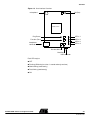
1
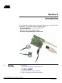
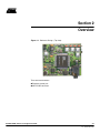
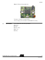
MP3 Player Reference Design
Based on AT89C51SND1
Microcontroller
..............................................................................................
User Guide
Table of Contents
Section 1
Introduction...............................................................................................1
1.1
1.2
Web Site download...................................................................................... 1
Abbreviations............................................................................................... 2
Section 2
Overview ..................................................................................................3
2.1
2.2
User Interface .............................................................................................. 4
Quickstart .................................................................................................... 6
2.2.1
2.3
2.4
2.5
2.6
Power ON/OFF ..................................................................................... 6
Main Functions ............................................................................................ 6
Mode Functions ........................................................................................... 6
Alternate Functions...................................................................................... 7
Special Information...................................................................................... 7
Section 3
Overview of Modes...................................................................................8
3.1
3.2
3.3
3.4
Song Mode .................................................................................................. 8
Voice Mode.................................................................................................. 8
USB Mode ................................................................................................... 8
Erase Mode ............................................................................................... 10
Section 4
In-System Programming (ISP) ...............................................................11
4.1
4.2
AT89C51SND1 Reference Design User Guide
Using Hardware Conditions....................................................................... 11
Using Software Condition .......................................................................... 11
1
4207B–MP3–04/07
Section 1
Introduction
The AT89RFD-01 is an MP3 reader reference design based on the AT89C51SND1
microcontroller. The AT89RFD-01 has the following features:
• Upload and Download of Files Through a USB Interface
• Plays or Records Songs
• Adjustable Volume, Treble, Medium and Bass
• Record Voice Through a Microphone in .WAV Format
1.1
Web Site
download
1. Connect to:
https://www.atmel-nantes.fr/.mp3/at8xc51snd1c
User Name is: atmelmp3
Password is: snd3pass
2. Copy the at8xc51snd1c.zip file to your PC.
3. Unzip the package to your local hard drive.
AT89C51SND1 Reference Design User Guide
1-1
Rev. 4207B–MP3–04/07
Introduction
1.2
Abbreviations
AT89C51SND1: the MP3 microcontroller
ISP: In-System Programming
MP3: MPEG layer 3, a standard music format
PC: Personal Computer
USB: Universal Serial Bus
AT89C51SND1 Reference Design User Guide
1-2
4207B–MP3–04/07
Section 2
Overview
Figure 2-1. Reference Design (Top view)
There are two connectors:
Earphone stereo jack
Mini-B USB connector
AT89C51SND1 Reference Design User Guide
2-3
Rev. 4207B–MP3–04/07
Overview
Figure 2-2. Reference Design (bottom view)
The battery is a standard 1.5V-battery type AAA.
The mass storage system on the board is a 64 MB NAND Flash memory.
2.1
User Interface
The user interface has 4 LEDs and 5 push-buttons:
Play/Pause
Function
Previous - Minus
Next - Plus
ON (Pwr)
AT89C51SND1 Reference Design User Guide
2-4
4207B–MP3–04/07
Overview
Figure 2-3. User Interface Overview
microphone
ON (Pwr)
AT89C51SND1
LED n°1
Play/Pause
LED n°2
LED n°3
Function (Func)
headphone
connector
LED n°4
Previous/Minus
Next/Plus
USB connector
Each LED may be:
OFF
Flashing (ON during less than 1 second and only one time)
Slow blinking (continuously)
Fast blinking (continuously)
ON
AT89C51SND1 Reference Design User Guide
2-5
4207B–MP3–04/07
Overview
2.2
Quickstart
This procedure allows you to quickly play an MP3 song stored in the mass storage system. If the mass storage is empty or not formatted, see the following section regarding
MP3 upload (“USB Mode”).
4. If the player is battery powered, push the ON button. If the player is powered by
USB, plug the USB cable into your computer.
All LEDs flash to confirm the power is ON.
After a few seconds, depending of the mass storage type and size, LED n°1 is
ON: indicating Song Mode is selected.
5. Push the Play/Pause button to play the first MP3 song of the mass storage
medium.
LED n°1 blinks during music play.
6. If the player is battery powered, after 1 minute of inactivity (no music), the player
will be automatically turned off.
2.2.1
Power ON/OFF
Press the ON button to power the player. Power off is automatic after one minute of
inactivity (no music, no button pressed). When the player is connected to a PC using the
dedicated USB cable, the player is powered by the USB power line and the battery is
useless (and will not be discharged). Disconnecting USB cable will automatically switch
supply to the battery without stopping the operation.
2.3
Main Functions
Main functions are the first meaning of the buttons:
Play/Pause: this button means Play/Pause or Select or Record
Function: to change the current mode or alternate function
Plus/Minus: to change a music track or change a control level
ON: to power on the player using the battery
2.4
Mode Functions
After power ON and initialization (step 1 of the previous section), there are 4 basic functions called “modes”, assigned to a dedicated LED:
LED n°1: Song Mode, to play the MP3 files of the embedded mass storage system
LED n°2: Voice Mode, to play or record short “wav” messages (phone quality)
LED n°3: USB Mode, to upload or download files to the embedded storage system
LED n°4: Erase Mode, to format the mass storage system
By pressing the Function key sequentially, the user will switch between these modes
(mode 1, 2, 3, 4, 1...). The LED ON indicates the current mode.
To validate one of these modes, press the Play/Pause button. For instance, if LED n°1
is ON, the current mode is “Song Mode”. The Play/Pause button will start the MP3
music.
AT89C51SND1 Reference Design User Guide
2-6
4207B–MP3–04/07
Overview
2.5
Alternate
Functions
When a mode is validated, the corresponding LED blinks slowly (except for USB mode,
LED n°3 blink quickly when mode is activated and more slowly during transfer). Alternate functions regarding this mode are then accessible using the Function button. One
LED blinking quickly is dedicated for each alternate function.
For Song Mode, alternate functions are:
LED n°1: Volume Control
LED n°2: Bass Control
LED n°3: Medium Control
LED n°4: Treble Control
LED n°2,3,4: Bass Boost Control
For Voice Mode, alternate functions are:
LED n°1: Volume Control
LED n°2: Stop and wait for Recording confirmation (to be validated by Play/Pause)
For other modes, there exist no alternate functions at the present time.
To adjust the controls, press Previous/Minus (to decrease) or Next/Plus (to increase)
the control level. A bar graph lights up for the corresponding control when one of these
buttons are pressed and during the adjustment, the control ranges from all LED OFF
(minimum level) to all LED ON (maximum level).
If no buttons are pressed for 3 seconds, the alternate functions setup ends and the LED
corresponding to the current mode blinks slowly (Play information).
2.6
Special
Information
Normally only one LED is ON or blinking at the same time. Exceptions are:
Change of Music Track: all LEDs flash one time
Start-up/Power ON: all LEDs flash one time
Voice Record: LEDs 1, 3 and 4 blink
Software ISP mode: LEDs 1 and 4 ON
Bar graph for the selected Control: from 0 to 4 LEDs ON
Error report: all LEDs are ON
Note: A possible error is that the mass storage system is not formatted. If this is the
case, press the Function button until Format Mode is selected and validate this
mode with the Play/Pause button.
All LEDs are off during:
Format process of mass storage
Initialization
Power OFF
AT89C51SND1 Reference Design User Guide
2-7
4207B–MP3–04/07
Section 3
Overview of Modes
3.1
Song Mode
This mode will allow users to listen to the MP3 song stored in the embedded mass storage system. If the memory is empty, LED n°1 does not blink and there is no music. If
there are valid MP3 files in the memory, the player will play the first song and LED n°1
blinks slowly.
Main and alternate functions give access to standard player functions.
3.2
Voice Mode
When entering Voice Mode, the first wav file in the directory will be selected and played.
When the player reaches the end of a wav file, or if wav file is not present, the player will
switch to record mode: LED n°2 blinks quickly. If the button Play/Pause is pressed, the
player records voices from the microphone. If the Function button is pressed, the player
will go back to its initial state (Voice Mode selected).
The microphone will record the voice and store it in the selected file until the maximum
size of the wav file is reached. When the maximum size is reached, the player will go
back to its initial state.
3.3
USB Mode
This mode will allow users to connect the player to a PC running under Linux®, Windows® 2000/XP/Me and MacOS® 9 (without driver) or Windows 98 (with a driver). The
Data Storage Flash will then be seen as a removable disk drive and copying from any
PC storage media to the player memory will be possible. Current firmware does not support Windows Format function.
Prior to entering this mode, a USB cable has to be connected between the PC and the
player. The player will then be powered by the USB supply. When entering USB mode,
USB lines will be activated and a device will appear in the Hardware window of the PC.
Note: First connection may require the driver installation depending of your Operating
System.
When connected, LED n°3 blinks quickly. When a file is moved to the player, this LED
does not blink regularly. Transfer is completed when the LED continues to blink quickly
and regularly.
Note: The file will appear in the removable media window on the PC before the end of
the transfer (almost at the beginning!).
Do not disconnect the cable during an on-going transfer.
AT89C51SND1 Reference Design User Guide
3-8
Rev. 4207B–MP3–04/07
Overview of Modes
In order to leave this state, the Play/Pause button must be pressed.
Do not disconnect the cable before leaving USB Mode.
3.4
Erase Mode
When this mode is validated by pressing Play/Pause button, all LEDs are OFF during
the erasing and reformatting of the full on-board mass storage system. LED n°4 will be
ON when this operation is performed.
AT89C51SND1 Reference Design User Guide
3-9
4207B–MP3–04/07
Section 4
In-System Programming (ISP)
4.1
Using Hardware
Conditions
Two solder points or short-cuts have to be physically set up on the board in order to
enter this mode. This mode must be used when the initial software has been corrupted
and when the ISP cannot be activated by the keyboard.
Figure 4-1. ISP Hardware Condition
Solder two SMD 0Ω resistors here (horizontally).
To activate the USB transfer and
To put hardware ISP conditions on the microcontroller.
4.2
Using Software
Condition
When connected to a PC using a USB cable, the player can be accessed by Flexible InSystem Programming (FLIP) software. To enter by software in the ISP bootloader of the
player, press the Function button while the USB cable is plugged into the PC (the ISP
software condition is checked only during power ON Reset).
A driver has to be installed the first time (See FLIP installation note). This driver is delivered with Atmel FLIP software available on the Atmel Web site.
When connected, a new device will appear in the hardware window of the PC under the
"User interface peripheral" section, named USB_DFU_SND1. See FLIP User's guide for
information about FLIP execution.
AT89C51SND1 Reference Design User Guide
4-10
Rev. 4207B–MP3–04/07
Atmel Corporation
2325 Orchard Parkway
San Jose, CA 95131, USA
Tel: 1(408) 441-0311
Fax: 1(408) 487-2600
Regional Headquarters
Europe
Atmel Sarl
Route des Arsenaux 41
Case Postale 80
CH-1705 Fribourg
Switzerland
Tel: (41) 26-426-5555
Fax: (41) 26-426-5500
Asia
Room 1219
Chinachem Golden Plaza
77 Mody Road Tsimshatsui
East Kowloon
Hong Kong
Tel: (852) 2721-9778
Fax: (852) 2722-1369
Japan
9F, Tonetsu Shinkawa Bldg.
1-24-8 Shinkawa
Chuo-ku, Tokyo 104-0033
Japan
Tel: (81) 3-3523-3551
Fax: (81) 3-3523-7581
Atmel Operations
Memory
2325 Orchard Parkway
San Jose, CA 95131, USA
Tel: 1(408) 441-0311
Fax: 1(408) 436-4314
Microcontrollers
2325 Orchard Parkway
San Jose, CA 95131, USA
Tel: 1(408) 441-0311
Fax: 1(408) 436-4314
La Chantrerie
BP 70602
44306 Nantes Cedex 3, France
Tel: (33) 2-40-18-18-18
Fax: (33) 2-40-18-19-60
ASIC/ASSP/Smart Cards
RF/Automotive
Theresienstrasse 2
Postfach 3535
74025 Heilbronn, Germany
Tel: (49) 71-31-67-0
Fax: (49) 71-31-67-2340
1150 East Cheyenne Mtn. Blvd.
Colorado Springs, CO 80906, USA
Tel: 1(719) 576-3300
Fax: 1(719) 540-1759
Biometrics/Imaging/Hi-Rel MPU/
High Speed Converters/RF Datacom
Avenue de Rochepleine
BP 123
38521 Saint-Egreve Cedex, France
Tel: (33) 4-76-58-30-00
Fax: (33) 4-76-58-34-80
Zone Industrielle
13106 Rousset Cedex, France
Tel: (33) 4-42-53-60-00
Fax: (33) 4-42-53-60-01
1150 East Cheyenne Mtn. Blvd.
Colorado Springs, CO 80906, USA
Tel: 1(719) 576-3300
Fax: 1(719) 540-1759
Scottish Enterprise Technology Park
Maxwell Building
East Kilbride G75 0QR, Scotland
Tel: (44) 1355-803-000
Fax: (44) 1355-242-743
Literature Requests
www.atmel.com/literature
Disclaimer: The information in this document is provided in connection with Atmel products. No license, express or implied, by estoppel or otherwise, to any
intellectual property right is granted by this document or in connection with the sale of Atmel products. EXCEPT AS SET FORTH IN ATMEL’S TERMS AND CONDITIONS OF SALE LOCATED ON ATMEL’S WEB SITE, ATMEL ASSUMES NO LIABILITY WHATSOEVER AND DISCLAIMS ANY EXPRESS, IMPLIED OR STATUTORY
WARRANTY RELATING TO ITS PRODUCTS INCLUDING, BUT NOT LIMITED TO, THE IMPLIED WARRANTY OF MERCHANTABILITY, FITNESS FOR A PARTICULAR
PURPOSE, OR NON-INFRINGEMENT. IN NO EVENT SHALL ATMEL BE LIABLE FOR ANY DIRECT, INDIRECT, CONSEQUENTIAL, PUNITIVE, SPECIAL OR INCIDENTAL DAMAGES (INCLUDING, WITHOUT LIMITATION, DAMAGES FOR LOSS OF PROFITS, BUSINESS INTERRUPTION, OR LOSS OF INFORMATION) ARISING OUT
OF THE USE OR INABILITY TO USE THIS DOCUMENT, EVEN IF ATMEL HAS BEEN ADVISED OF THE POSSIBILITY OF SUCH DAMAGES. Atmel makes no
representations or warranties with respect to the accuracy or completeness of the contents of this document and reserves the right to make changes to specifications
and product descriptions at any time without notice. Atmel does not make any commitment to update the information contained herein. Unless specifically providedotherwise, Atmel products are not suitable for, and shall not be used in, automotive applications. Atmel’s products are not intended, authorized, or warranted for use as components in applications intended to support or sustain life.
©2007 Atmel Corporation. All rights reserved. Atmel®, logo and combinations thereof, and Everywhere You Are ® are the trademarks or registered trademarks, of Atmel Corporation or its subsidiaries. Other terms and product names may be trademarks of others.
Printed on recycled paper.