1
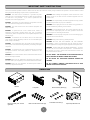
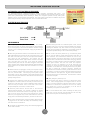
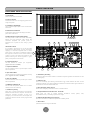
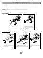
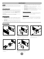
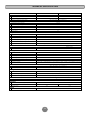
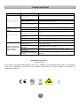
User’s Manual
PR5000ELCDRTXL5U
PR6000ELCDRTXL5U
K01-0000166-00
IMPORTANT SAFETY INSTRUCTIONS
This manual contains important instructions. Please read and follow all instructions carefully during installation and operation of the unit. Read this manual
thoroughly before attempting to unpack, install, or operate the UPS.
CAUTION! When installing the equipment, ensure that the sum of the
leakage current of the UPS and the connected equipment does not
exceed 3.5mA.
CAUTION! The UPS must be connected to a grounded AC power
outlet with fuse or circuit breaker protection. DO NOT plug the UPS into
an outlet that is not grounded. If you need to power-drain this
equipment, turn off and unplug the unit.
CAUTION! This is permanently connected equipment and only qualified
maintenance personnel may carry out installations.
CAUTION! The battery can power hazardous components inside the
unit, even when the AC input power is disconnected.
CAUTION! Do not unplug the unit from AC Power during operation, as
this will invalidate the protective ground insulation.
CAUTION! The UPS should be near the connected equipment and
easily accessible.
CAUTION! To avoid electrical shock, turn off and unplug the unit first,
then install the input/output power cord with grounded. Connect the
ground wire prior to connecting the line wires!
CAUTION! To prevent the risk of fire or electric shock, install in a
temperature and humidity controlled indoor area, free of conductive
contaminants. (Please see specifications for acceptable temperature and
humidity range).
CAUTION! Do not use improper size power cord to avoid damaging your
equipment and avoid fire hazards.
CAUTION! To reduce the risk of an electric shock, do not remove the
cover, except to service the battery. There are no user serviceable parts
inside, except for the battery.
CAUTION! Wiring must be done by qualified personnel.
CAUTION! DO NOT USE FOR MEDICAL OR LIFE SUPPORT
EQUIPMENT! Under no circumstances this unit should be used for
medical applications involving life support equipment and/or patient care.
CAUTION! To avoid electrical shock, turn off the unit and unplug it from
the AC power source before servicing the battery or installing a computer
component.
CAUTION! To reduce the risk of fire, connect the UPS to a circuit with
30 amperes maximum over-current protection in accordance to CE
requirement.
CAUTION! DO NOT USE WITH OR NEAR AQUARIUMS! To reduce
the risk of fire, do not use with or near aquariums. Condensation from
the aquarium can come in contact with metal electrical contacts and
cause the machine to short out.
CAUTION! The AC outlet where the UPS is connected should be close to
the unit and easily accessible.
DO NOT INSTALL THE UPS WHERE IT WOULD BE EXPOSED TO
DIRECT SUNLIGHT OR NEAR A STRONG HEAT SOURCE!
CAUTION! Please use only VDE-tested, CE-marked mains cable, (e.g.
the mains cable of your equipment), to connect the UPS to the AC outlet.
DO NOT BLOCK OFF VENTILATION OPENINGS AROUND THE
HOUSING!
CAUTION! Please use only VDE-tested, CE-marked power cables to
connect any equipment to the UPS.
DO NOT CONNECT DOMESTIC APPLIANCES SUCH AS HAIR
DRYERS TO UPS OUTPUT SOCKETS
UNPACKING
UPS unit
Rack mount rails (1 set – left and
right sides)
Front panel
Rack mount ears (Stands) (2)
Rack mount ear & rails screws (34)
1
Screw hole dust covers (8)
User’s manual
Input/ Output terminal cover
INSTALLING YOUR UPS SYSTEM
AUTOMATIC VOLTAGE REGULATOR(AVR)
The PR5000ELCDRTXL5U/ PR6000ELCDRTXL5U stabilizes damaging inconsistent utility power. The
Automatic Voltage Regulator automatically regulates low or high voltages to keep equipment working at safe AC
power levels (220/230/240V) without switching to battery. Your equipment operates normally when power
problems, such as, shout brownouts and blackouts. The unit’s powerful sealed lead-acid batteries will provide
power during the incoming voltage drops below 151V or increases above 302V.
SYSTEM BLOCK DIAGRAM
HARDWARE INSTALLATION GUIDE
1. Battery charge loss may occur during shipping and storage.
8. Before storing the UPS for an extended period of time, turn the
Before using the UPS, it’s strongly recommended to charge batteries
for four hours typically to ensure that the batteries’ maximum charge
capacity is met. To recharge the batteries, simply plug the UPS into
an AC outlet.
unit OFF. Then cover it and store it with the batteries fully charged.
Recharge the batteries every three months to ensure good battery
capacity and long battery life. Maintaining a good battery charge will
help prevent possible damage to the unit from battery leakage.
2. When using the included software, connect either the serial or the
9. The unit has one Primary Serial Port (I), one Secondary Serial
USB cable between the computer and the corresponding port on the
UPS. Note: If the USB port is used, the serial port will be disabled.
They cannot be used simultaneously. The computer with the
PowerPanel® Business Edition Agent software connects to the USB
port or the Serial port on the UPS. It can control the operating
schedule, battery test, outlet, etc. and obtain information on the UPS
status. However, other computers with PowerPanel® Business Edition
Client software can only obtain UPS status information via a LAN
connection.
Port (II), and one USB port, (paired with the Primary Serial Port), to
allow connection and communication between the unit and any
attached computers. The Primary Serial Port (I) as well as its paired
USB port allow for bi-directional communication among the UPS and
the primary connected computer running the PowerPanel® Business
Edition Agent software. The UPS can control the computer’s
shutdown in case of an emergency, and at the same time, the
computer can monitor the UPS and alter its various programmable
parameters. On the other hand, secondary Serial Port II, only allows
the UPS to initiate the connected computer’s (installed the
PowerPanel® Personal Edition software) graceful shutdown in case of
an emergency. If necessary, please download PowerPanel® Personal
Edition software at www.cpsww.com. DO NOT install PowerPanel®
Business Edition Agent and PowerPanel® Personal Edition software
on the same computer.
3. With the UPS off and unplugged, connect your computer, monitor,
and any externally powered data storage device (Hard drive, Tape
drive, etc.) into the outlets. DO NOT plug a laser printer, copier,
space heater, vacuum, paper shredder or other large electrical device
into the UPS. The power demands of these devices will overload and
possibly damage the unit.
10. EPO (Emergency Power Off) Port:
4. To protect a fax, telephone, modem line or network cable, connect
Use the provided gray cable to connect to a special EPO contact
switch. Follow the appropriate circuit diagram below to wire the
cable to your EPO configuration. The EPO remote switch is a switch
installed in an outside area, connected to the unit via an ordinary
RJ-11 phone line. In case of an emergency, it can be used to
immediately cut off power from the UPS unit.
the telephone or network cable from the wall jack outlet to the jack
marked “IN” of the UPS. Then, connect a telephone cable or network
cable from the jack marked “OUT” on the UPS to the modem,
computer, telephone, fax machine, or network device.
5. Press the power switch to turn the UPS on. The Power-On
indicator light will illuminate. If an overload is detected, an audible
alarm will sound and the UPS will emit one long beep. In order to
reset it, turn the unit off and unplug some equipment from outlets.
Make sure your equipment carry a load current within the unit’s safe
range, (refer to the technical specifications), and then turn the unit on.
11. To avoid electrical shock, before hardwiring the UPS (in/out
power cord), turn the unit OFF and disconnect the unit from utility
power. The in/out power cord MUST be grounded.
6. Your UPS is equipped with an auto-charge feature. When the UPS
is plugged into an AC outlet, the battery will automatically charge,
even when the unit is switched off.
7. To maintain an optimal battery charge, leave the UPS plugged into
an AC outlet at all times.
2
BASIC OPERATION
FRONT/REAR PANEL DESCRIPTION
1. Power Switch
Master On/Off switch for the UPS.
2. Power on Indicator
Indicates the UPS is on and supplying power free of
surges and spikes.
3. LCD Readout Toggle Button
Use to rotate through multiple screens of UPS status
information.
4. Multifunction LCD Readout
An illuminated digital screen that displays the UPS
power status information.
5. Battery Backup & Surge Protected Outlets
This unit provides a total of ten outlets with battery
backup and surge protection. They ensure that
connected equipment will provide power to
equipment over a period of time, during a power
failure.
3 2 1
4
9
10
Expansion Port
Critical /Non-Ccritical
It is possible to program the unit so that the outlet
block marked as “Non-Critical”, (5 ports), will stop the
supplying to connected equipment after a certain
period of time. This allows for additional runtime for 5
the equipment connected on the outlets marked as
“Critical”, (5 ports). This allows the creation of load
priorities ensuring the critical equipment is given
priority under specific circumstances.
8
11 12 13 14 15
Provides SNMP Card Communication
7
6. Output Terminal Block
Use this terminal to connect your equipment.
(Typical wire size is 10 AWG.)
7. Output Circuit Breaker
The circuit breaker serves to provide output overload
and fault protection.
8. Input Terminal Block
Use this terminal to connect the UPS System to utility
power. (Typical wire size is 10 AWG.)
9. Input Circuit Breaker
The circuit breaker serves to provide input overload
and fault protection.
10. SNMP/HTTP Network slot
Slot to install the optional SNMP card for remote
network control and monitoring.
11. Serial Port I (Primary)
Serial port I provides bi-directional communication
between the UPS and the computer. The UPS can
control the computer’s shutdown in case of an
emergency, and at the same time, the computer can
monitor the UPS and alter its various programmable
parameters.
6
17
16
12. Serial Port II (Secondary)
Serial Port II allows the UPS to initiate a connected computer’s graceful auto-shutdown in case
of an emergency.
13. USB port to PC
This is a connectivity port allowing communication and control between the UPS and the
connected computer. You should install the PowerPanel® Business Edition Agent software on
the PC/Server connected with the USB cord.
14. EPO (Emergency Power Off) Port:
Allows for an emergency UPS Power-Off from a remote location.
15. Surge Protected Communication Ports - RJ11/RJ45
These ports are used to protect standard RJ-45/RJ-11
Phone/Modem-Lines), and cabling systems from surges.
16. Extended Runtime Battery Pack Connector
Provides a connection for additional CyberPower XL Battery Packs
17. Ground Stud
Use the Ground Stud to ground the UPS.
.
3
based, (ADSL,
LAN,
HARDWIRE THE INPUT/ OUTPUT TERMINALS
CAUTION! To avoid electrical shock, before hardwiring the UPS (in/out power cord), turn the unit OFF and disconnect the unit from utility power. The in/out
power cord MUST be grounded.
CAUTION! To avoid electrical shock, turn off and unplug the unit first, then install the input/output power cord with grounded. Connect the ground wire prior to
connecting the line wires!
CAUTION! Do not use improper size power cord to avoid damaging your equipment and avoid fire hazards.
CAUTION! Wiring must be done by qualified personnel.
INPUT TERMINALS
1 Pass user-supplied cable through the input terminal
○
cover and attach it to the input terminals.
2 Secure the input panels (supplied), to
○
the UPS using four of the screws removed
from the input panel.
OUTPUT TERMINALS
1 Turn the knob to the left to loosen the
○
2 Pass user-supplied cable through the output
○
3 Turn the knob to the right to tighten
○
knob and take it out.
terminal cover and attach it to the output terminals.
the cable.
4
HARDWARE INSTALLATION
HARDWARE INSTALLATION
Step 4: Adjust rack mount rails to fit your rack
These versatile UPS systems can be mounted in a rack mount or vertical
/tower orientation. This versatility is especially important to growing
organizations with changing needs that value having the option to position a
UPS on a floor or in a rack mount system. Please follow the instructions
below for the respective mounting method.
Take the rack mount rail inscribed with an “L” (Left) and attach it to the
rear bracket of the Rack-mount Rail using three (3) of the six (6)
Rack-mount Rail Screws. Do not fully tighten the rack mount rail
screws, as the rack mount rails will need to be adjusted to fit your rack.
Once complete, perform the same steps for assembling the Rack-mount
Rail inscribed with an “R” (Right).
SAFETY PRECAUTIONS
CAUTION! To prevent the risk of fire or electric shock, use only the supplied
hardware to attach the mounting brackets.
RACKMOUNT INSTALLATION
Step 1: Take out the internal battery modules first. (See page 10)
Step 2: Rack mount ears installation
Attach the two rack mount ears to the UPS using the provided screws.
Step 5: Carefully align the front panel connector and latches with
the PR5000ELCDRTXL5U/ PR6000ELCDRTXL5U
Step 3: Rack mount rail Installation
Ensure rack stability prior to installing devices in the rack.
CAUTION! The UPS must be installed at the bottom of the rack system.
CAUTION! Do not lift the front panel when removing the UPS unit.
Attach the rack mount rails to your rack using fasteners that are designed
for your rack system.
5
HARDWARE INSTALLATION
VERTICAZL/TOWER INSTALLATION
Step 1: Attach the base stands
Simply slide the base stands onto the bottom of the UPS, roughly 8-10”
apart.
Step 2: Attach dust covers
Insert dust covers into the rack mount ear screw holes that are not being
used.
Step 3: Rotate the Multifunction LCD Readout
Separate the front panel and the UPS. Gently lift the LCD out. Rotate it to the preferred orientation. Reinstall the display for a tower configuration.
ELECTRICAL INSTALLATION
After completing the hardware installation of the UPS, you are now ready to plug in the UPS and attach your equipment.
SAFETY PRECAUTIONS
•
•
•
•
CAUTION! - Installation environment should be in a temperature and humidity controlled indoor area free of conductive contaminants. Do not install
this UPS where excessive moisture or heat is present (Please see specifications for acceptable temperature and humidity range)
CAUTION! - Never install a UPS, or associated wiring or equipment,
during a lightning storm.
CAUTION! - Do not work alone under hazardous conditions.
CAUTION! - To reduce the risk of electric shock, do not remove the
top cover.
•
CAUTION! - The battery can energize hazardous live parts inside
even when the AC input power is disconnected.
6
DEFINITION FOR ILLUMINATED LCD INDICATORS
MULTIFUNCTION LCD READOUT
The multifunction LCD readout provides ready access to power/battery condition vitals, such as:
Runtime, Load, Temperature, and much more.
The screen is also rotatable so the UPS can be used in either rack mount or vertical/tower
orientation.
BASIC OPERATION
Screen toggle – To toggle through the status screens press the Select button which is located directly next to the
LCD.
Screen illumination– After 30 seconds of inactivity, the LCD backlight will automatically turn off to conserve
energy. Keeping the LCD screen lit at all times is not an option on this UPS.
Select Button
•
•
•
If the LCD screen is not lit pressing the Select button once will turn the LCD on. If the LCD screen is lit, then
pressing the Select button once will toggle through the status screens.
Pressing and holding the Select button for four (4) seconds while UPS is in Normal operation will initiate the Self
Test.
Pressing and holding the Select button for four (4) seconds while UPS is in Battery/Offline mode will activate Silent
Mode on the UPS.
Select Button
MAIN FEATURES
Load Level: The total
load of the connected
equipment shown in
20% increments.
Silent icon: This icon appears when the
UPS is in silent mode. During Silent mode,
the unit’s alarm does not sound until the
Battery Capacity falls to < 20%.
Battery Capacity: The
battery’s current charge
level shown in 20%
increments.
Normal Icon: This icon
appears when the UPS
is working under normal
conditions.
Overload icon: This icon appears
when the Battery/Surge outlets on the
UPS are overloaded. The UPS will
also sound an alarm at this point. To
clear the overload, the total load of the
connected equipment must be less
than the unit’s maximum capability.
The easiest way to correct this
problem is to remove noncritical
equipment from the Battery/Surge
outlets.
Fault icon: This icon appears if there is
an internal problem with the UPS.
Please contact Technical Support if
this icon is lit.
Automatic Voltage Regulation (AVR) icon: This icon
appears when the UPS is automatically correcting
AC input line voltage without using battery power.
This is a normal, automatic operation of your UPS,
and no action is required. The AVR in this UPS
continuously conditions the power to a nominal
220/230/240V output to connected equipment. In the
event of a complete power loss, severe brownout, or
over voltage, the UPS relies on its internal battery
back up to supply a consistent 220/230/240V output.
Battery Icon: This icon appears when the UPS is
operating using battery power. The UPS will also
sound alarms (two short beeps followed by a pause)
when this icon is lit. When the Battery Icon is lit and
the Battery Capacity falls to 20% the frequency of
the alarms will increase indicating that the UPS
batteries are nearly out of power. If this occurs, it is
recommended that you either restore AC power, or
manually power down your equipment that may be
negatively affected by sudden power loss.
7
DEFINITION FOR ILLUMINATED LCD INDICATORS
TOGGLE SCREENS
Input Voltage
Output Voltage
The Input Voltage screen displays the AC
voltage that the UPS system is receiving
from the utility wall receptacle. This can
be used as a diagnostic tool to identify
poor quality input power. Units are
listed in V (Volts).
The Output Voltage screen measures, the
AC voltage that the UPS is providing to
your connected equipment via the UPS
outlets. Units are listed in V (Volts).
Estimated Runtime
Output Frequency
The Estimated Runtime Screen displays
how many minutes of runtime can be
expected of the UPS if it were to
experience a power outage. Note: The
number displayed may be less than
actual runtimes for low loads.
The Output Frequency screen displays
the current frequency at which the UPS
is operating. Units are listed in Hz
(Hertz).
Load Capacity
Battery Capacity
Similar to the Load/Current Level screen,
this displays the total load/current of the
connected equipment expressed as a
percentage (%).
The Battery Capacity screen displays the
battery’s current charge level and is
expressed as a percentage (%) of the
battery’s total capacity of 100%.
Temperature
Temperature
The Temperature screen displays the
internal temperature of the UPS in
degrees Centigrade. Normal ranges are
0℃-40℃. If the temperature exceeds
40℃, additional methods should be
implemented to cool the UPS (i.e. air
conditioning,
additional
ventilation,
isolation from other heat producing
equipment, etc.).
The Temperature screen displays the
internal temperature of the UPS in
degrees Fahrenheit. Normal ranges are
32℉-104℉. If the temperature exceeds
104℉, additional methods should be
implemented to cool the UPS (i.e. air
conditioning,
additional
ventilation,
isolation from other heat producing
equipment, etc.)
Load
This displays the total load/current of the
connected equipment.
8
LCD SETUP FUNCTIONS
1. General Mode:
a. Press the “Display-Toggle” button to check the status of the UPS
These programmable items are sorted by unit as in the following table:
status:
1
2
3
4
5
6
7
8
9
Item
Unit
Input Voltage
Output Voltage
Output Frequency
Load
Estimate Run Time
Load Capacity
Battery Capacity
Centigrade
Fahrenheit
V
V
Hz
Kw
Min
%
%
℃
℉
Items
Unit
Delay Time
Battery Pack Numbers
Voltage Mode (220/230/240)
Static Frequency Tolerance
Slew Rate
Low Battery Shutdown Voltage
Firmware Version
Min
A
V
%
Hz
V
None
Step 3: Press and hold the display-toggle for 4 seconds. When the
icons blink, the value of each item is changed by slightly pressing the
toggle.
b. Press and hold the “Display-Toggle” button for 4 seconds,
If the machine is in the Battery Mode with active alarm, it will become
silent.
If the machine is in the Line Mode, a self- diagnostic test will take
place.
Step 4: To save the value and return to general mode, press and hold
the toggle for 4 seconds.
Note! If the UPS is left idle for over 30 seconds
during setup, it will turn off the backlight and
return to general mode automatically.
c. If the “Display-Toggle” button remains untouched for over 30
seconds, the LCD backlight will turn off automatically.
Note! If the user does not want to save the new
settings and return to the general mode, there are
two methods:
(1) Wait for the backlight to turn off, or,
(2) By pressing and holding the “Display-toggle” key for 10
2. Set-up Mode
Step 1: Hold the “Display-Toggle” button for 10 seconds to enter the
UPS Set-Up Mode.
second.
Step 2: By pressing the Display toggle, users can switch between
setup functions. Some User Configurable functions are as follows:
a. Delay Time: The time delay between switching from Battery Mode
to Line Mode. There are 9 different settings. The default setting is
0 minutes.
GreenPower UPS™
b. Battery Pack Numbers: This function provides the estimated UPS
CyberPower's GreenPower UPS™ Circuit
Design is a solution to this problem "Power
Loss." When the Utility Power is operating
normally, Green Power UPS™ works in Bypass
Mode.
Our GreenPower UPS™ design conducts
power only through the Relay and still provides
normal output voltage. Bypassing the
transformer reduces power consumption
thereby conserving energy and saving money. When the utility power is
abnormal the UPS will operate under Battery or AVR Mode. Under this
condition Green Power UPS™ and a traditional UPS would operate
about the same.
On average utility power operates 88% of the time and the CyberPower
GreenPower Technology will work in its money/ energy saving Bypass
Mode.
runtime using various numbers of battery packs. The default
setting is 0.
c. Voltage Mode: There are 3 settings (220, 230, 240), and set the
acceptable voltage according your location.
d. Static Frequency Tolerance: There are 4 settings (1, 2, 4, 6 %),
and the default setting is +/-6%. Functional description: The
setting may be adjusted to the quality of the electricity in use.
e. Slew rate: Also known as Dynamic Frequency Tolerance. There
are 5 different settings (0.25, 0.5, 1, 2, 4 Hz/Sec). The default
value is 4Hz/sec. Functional Description: “Slew Rate” indicates
the tolerance of a device in accepting frequency variance. Lower
“Slew Rate” results in less tolerance but better protection for the
connected load and vice versa.
f.
Low Battery Shutdown Voltage: This function will adjust the UPS
shutdown point according to the battery’s remaining capacity.
9
MAINTENANCE
Storage
To store your UPS for an extended period, cover it and store with the
battery fully charged. Recharge the battery every three months to ensure
battery life.
•
•
Battery Replacement
•
Please read and follow the Safety Instructions before servicing the
battery. Battery replacement should be performed by trained personnel
who are familiar with the procedures and safety precautions. Make a note
for the replacement battery pack number, (RBP843a/RBP843b),
regarding PR5000ELCDRTXL5U and PR6000ELCDRTXL5U.
Replacement Batteries
Please refer to the front side of the battery module for the model number
of the correct replacement batteries. To purchase these batteries, log
onto www.CPSww.com, or contact your local dealer.
CAUTION! – Put the battery pack marked RBP843b into the UPS
unit first, and then put the battery pack marked RBP843a.
Battery Disposal
Safety Precautions
•
•
any conductive materials such as jewelry, chains, wrist watches,
and rings.
CAUTION! - Do not open or mutilate the batteries. Electrolyte
fluid is harmful to the skin/eyes and may be toxic.
CAUTION! - To avoid electrical shock, turn off and unplug the UPS
from the wall receptacle before servicing the battery.
CAUTION! – Only use tools with insulated handles. Do not lay
tools or metal parts on top of UPS or battery terminals.
Batteries are considered hazardous waste and must be disposed of
properly. Contact your local government for more information about
proper disposal and recycling of batteries. Do not dispose of batteries
in a fire.
CAUTION! – Only use replacement batteries which are certified
by CyberPower Systems. Use of incorrect battery type is an
electrical hazard that could lead to explosion, fire, electrical shock,
or short circuit.
CAUTION! – Batteries contain an electrical charge that could
cause severe burns. Before servicing batteries, please remove
Battery Installation
1 Remove the front panel.
○
4 Put the new battery modules back into the
○
compartment.
2 Remove the retaining screws of the cable
○
3 Pull the plastic sticker out slowly to
○
protection cover, and then remove the cover
itself.
remove the battery module.
5 Tighten the screws and replace the cable
○
protection cover and the front panel.
10
TECHNICAL SPECIFICATIONS
Model
Configuration
Capacity (VA)
Capacity (Watts)
Energy-saving Technology
Input
Nominal Input Voltage
Input Voltage Range
Input Adjustable Voltage Range
Frequency Range
Input Plug Type
Cold Start
Output
Output Voltage Note
UPS Outlets
On Battery Output Voltage
On Battery Output Frequency
Transfer Time (Typically)
Overload Protection
Data line Protection
Surge Protection
Phone / Network Protection
Battery
PR5000ELCDRTXL5U
PR6000ELCDRTXL5U
5000VA
4000W
6000VA
4500W
GreenPower UPS™ Bypass
230V
159-288V
151-302V
50/60Hz +/- 3Hz
(1) Terminal block
Yes
Configurable for 220/ 230/ 240 nominal output voltage
(8) IEC C 13, (2) IEC C19, (1) Terminal block
Pure Sinewave, 230V +/- 5%
50Hz+/- 0.1Hz
4ms
On Utility: Circuit Breaker; On Battery: Internal Current Limiting
2430Joules
2430Joules
RJ11/RJ45 (One In/One Out)
Specifications
Sealed, Maintenance Free
User Replaceable
Recharge Time (Typically)
Status Indicators
Indicator LEDs
Audible Alarms
Environment
Operating Temperature
Operating Relative Humidity
Management
(16) 12V/9.0AH
Yes
Yes
4 hours
Power On, LCD Display (Using Battery, AVR, Load Level, Battery Level)
On Battery, Low Battery, Overload
32℉ to 104℉ ( 0℃ to 40℃)
0 to 95% Non-Condensing
On-Device Features
Connectivity Ports
Self Test, Auto-Charge, Auto-Restart
(1) USB, (2) Serial
SNMP/HTTP Capable
Software
Power Management Software
Physical
Dimensions (LxWxH) (mm)
Weight (kg)
Safety
Conformance Approvals
Yes [With optional RMCARD 202]
®
PowerPanel Business Edition
640 x 430 x 222
101
103
CE, C-tick
11
TROUBLE SHOOTING
Problem
Possible Cause
Circuit breaker has tripped due
to an overload.
Outlet does not provide
power to equipment
The UPS does not
perform expected
runtime.
The UPS will not turn
on.
PowerPanel® Business
Edition/ PowerPanel®
Personal Edition
Edition is inactive.
Batteries are discharged.
Unit has been damaged by a
surge or spike.
Uncritical outlets have
turned off automatically
due to an overload.
Batteries are not fully charged.
Batteries are degraded.
The on/off switch is designed to
prevent damage by rapidly
turning it off and on.
The unit is not connected to an
AC outlet.
Solution
Turn the UPS off and unplug at least one piece of equipment.
Wait 10 seconds, reset the circuit breaker and then turn the UPS
on.
Recharge the unit for at least 4 hours
Contact CyberPower for repair.
Push the toggle button to make the uncritical outlets turn on.
Recharge the batteries by leaving the UPS plugged in.
Contact CyberPower for repair.
Turn the UPS off. Wait 10 seconds and then turn the
UPS on.
The unit must be connected to a 220/230/240v outlet.
The batteries have degraded.
Contact CyberPower for repair.
Mechanical problem.
Contact CyberPower for repair.
The serial cable or USB cable
is not connected.
The cable is connected to the
wrong port.
The unit is not providing power
of batteries.
The serial cable is not the
cable that was provided with
the unit.
Connect the cable to the UPS unit. You must use the cable that
came with the unit.
Try another port of your computer.
Shutdown your computer and turn the UPS off. Wait 10
seconds and turn the UPS back on. This should reset the unit.
You must use the cable included with the unit for the
Software.
CyberPower Systems Inc.
www.cpsww.com
Entire contents copyright ©2010 CyberPower Systems Inc., All rights reserved. Reproduction in whole or in part without
®
®
permission is prohibited. PowerPanel Business Edition and PowerPanel Personal Edition are trademarks of
CyberPower Systems Inc.
12