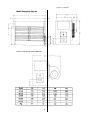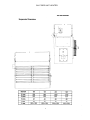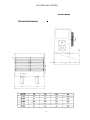
1
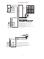
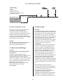
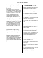
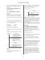
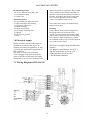
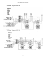
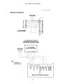
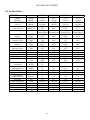
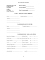
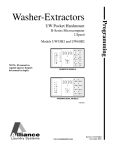
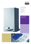
OIL FIRED UNIT HEATER
1
OIL FIRED UNIT HEATER
CONTENTS
Compliance notices
3
Certificates of Conformity
4
General Information
4
Delivery Checks
5
Warranty
5
Heater Dimensions
6
Suspension Details
7
Wall Mounting Dimensions
8
Installation
9
Air Supply
10
Fuel System
10
Flue System
12
Commissioning Pre test
13
Commissioning Ignition
14
Servicing
15
Electrical Supply
16
Wiring Diagrams
16-18
Technical Data
19
2
OIL FIRED UNIT HEATER
Section B Warranty Section C User Instructions
19-21
Benson Heating Ltd, to ensure that they are
familiar with the appropriate
information/manuals, supplied by the
manufacturer, and that they are suitably
aware of the purpose of the manuals and the
safety instructions. In addition, operators
must be suitably trained in the use of the
appliance so as to ensure its continued safe
and efficient use.
Benson Heating Ltd has a commitment to
continuous improvement, and therefore
reserves the right to amend or change the
specification of the Unit Heater range subject
to compliance with the appropriate European,
National, and Local Regulations.
1.0 Compliance notices
The following information is relevant to the
Benson Heating Ltd Oil Fired Unit Heater
range (OUHA) and (OUHC) manufactured
for. These heaters are manufactured within a
strictly controlled quality environment within
the parameters of ISO 9002.
The OUHA (C) Heater range has been tested
and assessed for compliance with the
following European Directives.
Machinery Directive (89/392/EEC)
Low Voltage Directive (73/23/EEC &
93/68/EEC)
Electromagnetic Compatibility Directive
(89/336/EEC & 91/31/EEC)
Product Liability Directive (65/374/EEC)
Contained within the text of the manual, the
words 'Caution' and 'Warning' are used to
highlight certain points.
Caution is used when failure to follow or
implement the instruction(s) can lead to
premature failure or damage to the heater or
its component parts.
The manufacturer has taken reasonable and
practical steps to ensure that Oil Fired Unit
Heaters are safe and without risk when
properly used. These heaters should therefore
only be used in the manner and purpose for
which they were intended, and in accordance
with the recommendations detailed herewith.
Warning is used when failure to heed or
implement the instruction(s) can lead to not
only component damage, but also to a
hazardous situation being created where there
is a risk of personal injury.
The heaters have been designed,
manufactured, assembled, inspected, and
tested, with safety and quality in mind, there
are certain basic precautions which the
installer and user should be aware of, and
they are strongly advised to read the
appropriate sections of the information pack
accompanying the heater, prior to installation
or use.
The OUHA ( C ) Range conform to the
following harmonized standards;
BS EN 292 - Part 1 : 1991
Safety of Machinery - Basic Concepts,
General Principles for Design
Basic terminology, methodology
Benson Heating supports all new products
being supplied to their customers with a
comprehensive information pack; this clearly
defines mandatory instructions for the safe
installation, use, and maintenance, of the
appliance(s).
BS EN 292 - Part 2 : 1991
Safety of Machinery - Basic Concepts,
General Principles for Design
Technical Principles and Specifications
BS EN 60204 - Part 1 : 1993Safety of
Machinery - Electrical Equipment for
Machines Specification for General
Where proprietary items are incorporated into
Benson Heating Ltd products, detailed
information and instructions are also
provided as part of the information pack.
Requirements
BS EN 60335 - Part 1 : 1988
Safety of Household and Similar Electrical
Appliances General Requirements
It is the responsibility of the installer, owner,
user, or hirer, of such products supplied by
3
OIL FIRED UNIT HEATER
BS EN 55014 - 1993
Limits and methods of measurement of radio
disturbance characteristics of electrical
motor-operated and thermal appliances for
household and similar purposes, electrical
tools and similar electric apparatus
manufacturers recommendations may
constitute a hazard.
Note
To ignore the warning and caution notices,
and to ignore the advice from the
manufacturer on installation, commissioning,
servicing, or use, will jeopardise any
applicable warranty, moreover, such a
situation could also compromise the safe and
efficient running of the appliance itself, and
thereby constitute a hazard. The installation
of the appliance must meet all the relevant
European, National, and Local Regulation
criteria.
BS EN 50165 - 1995
Electrical Equipment of non-electric heating
appliances for household and similar
purposes, safety requirements
1.1 Certificates of conformity
Certificates are available from the Quality
Control Department at Benson Heating Ltd
Prior to installation the following points
should be considered;
1.2 General product information
a) The position of the heater for the efficient
distribution and circulation of warm air
The unit heater models have an output range
from 100,000 Btu to 339,000 Btu.
b) The position of the heater relative to the
route of the flue
Each heater must be connected to its own
individual open flue.
c) The position of the heater relative to the
supply of fuel
Each heater is fitted with a forced draught
burner which has been test fired and pre-set
prior to despatch. The safety functions of the
burner are by way of a fully sequential
control box fitted to the burner.
d) The position of the heater relative to the
electrical services, and if appropriate, any
additional controls.
Note
Neither asbestos nor soft soldered joints are
used in the construction or manufacture of
the Benson Heating Ltd range of Unit
Heaters. The materials selected for use can
withstand the mechanical, chemical, and
thermal stresses which they will be subject to
during foreseen normal use when installed in
accordance with the manufacturers
recommendations.
e) The position of the heater relative to the
supply of fresh air
f) The position of the heater relative to
service and maintenance requirements
Caution
The heater must not be installed within an
area where the conditions are unsuitable, e.g.
where the atmosphere is highly corrosive, has
a high degree of salinity, or where high wind
velocities may affect burner operation.
Suitable protection should be provided for the
appliance when it is located in a position
where it may be susceptible to external
mechanical damage from; for example, fork
lift trucks, overhead cranes etc.
1.3 General requirements
Caution
Ensure that the fuel supply is in accordance
with the manufacturer's recommendations
and is as stated on the appliance data plate.
Installation, commissioning, and servicing
must only be carried out by appropriately
qualified and competent persons.
Warning
Unauthorised modifications to the
appliance, or departure from the
manufacturers guidance on intended use,
or, installation contrary to the
4
OIL FIRED UNIT HEATER
1.4 Delivery and pre-installation
checks
f) The main electrical supply input to the
heater has been interrupted during the heating
mode
The heater is supplied wrapped in heavy duty
protective polythene. On receipt of the heater,
the following checks should be carried out;
(a Model is as per order
(b That it is undamaged
(c That it is suitable for the fuel supply
g) The heater has been subject to and affected
by the ingress of water in any form
h) The heater is not operated at the rating(s)
laid down in the manufacturers technical
specifications
(d That it is suitable for the electrical
supply
If any of the points are not satisfied then
contact should be made with the sales office
at Benson Heating Ltd as soon as possible by
telephoning 01547 528534. in the case of
claims for damage, this must be reported in
writing within 24 hours of delivery, in order
to comply with insurance criteria.
i) The heater has not been operated or used
within the normal scope of its intended
application
1.5 Warranty
All warranty claims must contain the
following information to enable processing
to take place;
(1) Heater model
(2) Heater serial number
(3) Order reference/date of order, together
with full installation details (name and
address)
(4) Details or symptoms of fault
(5) Installers name and address.
j) The manufacturer's recommended
minimum service requirements have not been
complied with
The heater is supplied with a 2 year warranty
comprising of the following 1 year parts and
labour
1 year parts only.
In addition to this there is also a 10 year time
related warranty on the combustion chamber.
The warranty commences from the date of
dispatch from the manufacturer, and is
subject to the terms detailed within the Harry
Taylor Ltd 'conditions of business'.
Faulty parts must be returned to the Benson
Heating Ltd Spares Department, the address
of which is provided at the back of this
manual. Any such parts will undergo
inspection to verify the claim. Replacement
parts supplied prior to this may be charged,
and a credit supplied upon subsequent
validation of the warranty claim.
Consumable items are specifically not
included within the scope of the warranty.
The warranty may be invalidated if a) The warranty registration and
commissioning card has not been completed
and returned to Harry Taylor Ltd
b) The installation is not in accordance with
the general requirements of this manual
Notification is required immediately a fault is
suspected.
The manufacturer will not accept
responsibility for any additional damage that
has been caused, expense incurred, or
consequential loss resulting from any failure
of the heater(s)
c) The flue arrangement and air supply for
the heater are not in accordance with the
manufacturers recommendations, codes of
practice, or similar standards
d) Air flow through the heater is not in
accordance with the manufacturers technical
specifications
e) Internal wiring on the heater has been
tampered with or Unauthorised
service/repairs undertaken
5
OIL FIRED UNIT HEATER
6
OIL FIRED UNIT HEATER
7
OIL FIRED UNIT HEATER
8
OIL FIRED UNIT HEATER
Suspended free blowing Unit Heaters are at
their most effective when located as close to
the working area as possible. However care
should be exercised to avoid directing the
discharged air directly onto the occupants of
the area to be heated.
2.0 Installation
Note
It is a requirement that only qualified and
competent personnel may undertake
installation commissioning and servicing of
OUHA ( C )Range Heaters.
Where the passage of cold air causes
problems (e.g by entrances, loading bays etc)
it is considered favourable if the heater is
positioned so as to discharge towards or
across the cold air source from a distance
from 1.5m - 6m dependent upon the size of
the entrance and the air throw characteristics
of the heater. On exposed walls heaters
should be positioned so as to discharge
towards, or along the length of the exposed
wall. In areas where it is proposed that more
than one heater is to be installed, a general
scheme of circulation should be drawn up
and maintained, thereby offering the best heat
distribution.
Air pressure within the area heated and the
outside air pressure must remain the same,
factors influencing this would be the presence
of extraction systems, ventilation systems,
and various types of process plant.
OUH 240/340 models can be installed to
allow the fans to work in opposite directions .
This enables the heater to be installed
centrally in the area to be heated and allows
warm air to be discharged to both the front
and rear of the heater
Warning
All of the basic criteria must be satisfied prior
to commencing installation and
commissioning, additionally, the Unit Heater
must be positioned and installed so as to
comply with all the relevant standards and
guide lines as well as meeting national and
local fire regulations and insurance criteria,
especially if it is proposed that the heater is to
be installed within a special risk area (e.g.
proximity to where petrol engined vehicles
are stored or parked, where cellulose
spraying takes place, where woodworking
machinery is operated, etc,).
Indirect fired heaters must not be located in
hazardous areas, however, it is permissible
for the heater to supply air to such areas.
The heater must not be installed within an
environment where there is a high
concentration of chlorides, fluorides, salts, or
other aggressive or volatile
chemicals/compounds.
Nor should the heater be positioned where
the burner could be adversely affected by
high winds or draughts.
The heater must be installed so that it is level.
Supports for the heater must be sufficiently
robust to withstand the weight of the heater
and any ancillary equipment. Any
combustible material adjacent to the heater or
flue system must be so placed or shielded so
that its surface temperature does not exceed
65C
The location chosen for the heater must allow
for the fitting of an effective flue system.
The location must also allow for adequate
clearance for the air supply, return air
circulation, oil supply, electrical supply,
whilst also providing good and safe working
access.
9
OIL FIRED UNIT HEATER
2.1 Air supply
If the heater is to be installed within its own
separate building or plant room, the above
details do still apply, as does the requirement
for minimum space.
Provision must be made for the existence of
an air supply for both combustion and
ventilation. It is a requirement that the area
where the air heater is located must have a
permanent air vent of negligible resistance
direct to the outside air. Such air vents must
be positioned so as not to become blocked or
flooded, nor should they be placed so as to
introduce undesirable matter (e.g. flammable,
volatile, or aggressive chemicals/compounds
or potentially hazardous or harmful
substances) either direct from the outside, or
through their proximity to an adjacent
extraction system.
The criteria necessary for establishing the
minimum size of natural vents is detailed as
follows;
Position of vent
Low level inlet
(< 60kW)
( >60kW)
3.0 Fuel
Three methods of fuel supply can be used to
supply fuel to the heaters
(a) Two pipe system
(b) Gravity Feed
(c) Pressurised ring main
Two pipe system
This is used where the oil storage tank is
lower than the pump.
Access for the fuel feed to the burner should
be via a suitable tapping made in the top of
the tank, and the fuel feed pipe should extend
to not less than 100mm above the bottom of
the tank. A non return valve with a metal to
metal seat should be fitted, especially if the
return pipe work is terminated at a level
above the draw off tube. The non- return
valve must be removable for service and
maintenance purposes, and the return pipe
from the pump must therefore be extended
down into the tank to the same level as the
suction pipe. The use of a tiger loop in this
type of installation will reduce the need of a
return pipe back to the tank
Maximum lift should not exceed 3.5 metres,
and the vacuum should not exceed 0.4 bar.
Position of Vent direct
to outside
9.0 cm ²per kW
540 cm ²+ 4.5 cm ²per kW
High level Outlet
(< 60kW)
4.5cm² per kW
( >60kW)
270cm ²+ 2.25cm² per kW
Enough air must be provided to meet the
needs of all fuel burning appliances, as well
as appliances such as exhaust fans which
force air out of the building
Where mechanical ventilation is used it is a
requirement that the inlet is of the mechanical
type, and the outlet is either mechanical or
natural.
Each heater must have a separate fuel
supply.
Gravity feed system
Caution
Systems of ventilation that employ
mechanical extraction and natural inlet must
not be used. Furthermore, where the air
supply is by way of a mechanical means the
inlet must be positioned at low level and be
capable of providing a minimum throughput.
The natural extraction air vents must have a
minimum area as per above, and it is strongly
recommended that natural extraction vents
are situated at high level. An automatic
control interlocked to the burner must be
fitted to ensure burner shutdown in the event
of airflow failure or restriction.
For installations where the oil tank is 200mm
or more above the level of the fuel pump the
principle of gravity feed may be used.
The draw off point for the supply to the
burner must not be positioned any lower than
100mm above the bottom of the tank.
Where a return valve is fitted this must be
tamper proof to prevent inadvertent
operation.
Each heater must have a separate fuel supply
10
OIL FIRED UNIT HEATER
H
Maximum
4 metres
H
m
0
0.5
1.0
1.5
2.0
3.0
3.5
I.D.
8mm
35.0
30.0
25.0
20.0
15.0
8.0
6.0
I.D.
10mm
100.0
100.0
100.0
90.0
70.0
30.0
20.0
BURNER
The pump suction should not exceed a maximum of 4 metres.
Beyond this limit gas is released from the oil.
H
The return line should terminate within the oil tank at the same level
as the suction line; in this case a non return valve is not required.
Should, however, the return line terminate over the fuel level,
a non return valve is essential.
This solution, however, is less safe than the previous one, due to
possibility of leakage of the valve.
Priming the pump: Start the burner and await priming.
Should lock-out occur prior to arrival of the fuel, wait at least 20 seconds
before repeating the operation.
BURNER
The pump suction must not exceed 4 metres;
beyond this value the pump becomes noisy.
H
The return valve must terminate at the same level
as the foot valve, otherwise the pump may
become air locked.
11
OIL FIRED UNIT HEATER
1 GATE VALVE
2 IN-LINE FILTER
3 PUMP
4 RELIEF VALVE
5 PRESSURE GAUGE
6 PRESSURE REDUCING VALVE
7 RETURN TO TANK
7
4
5
6
6
3
1
2
Pressurised ring main system
4.0 Flue system
This system is used to supply a number of
units from a common storage tank.
A booster pump is used to provide the
pressure to push the oil around the ring main
and back to the tank. Pressure reducing
valves should be fitted on the delivery pipe to
each heater to ensure that the pressure at the
burner pump is less than 6 psi.
Warning
It is essential that the products of combustion
are flued to the outside of the building. Each
heater must have its own separate flue, with a
flue diameter of not less than is detailed in
this manual. The minimum vertical length of
flue must not be less than 3m. The number of
bends should be kept to a minimum. It is
strongly advised that BS 5854; 1980, and BS
5440; parts 1 and 2, are used as consultative
documents when considering flue
requirements.
Care should be taken to ensure that the flue
terminal is not situated in a high-pressure
area, the proximity of buildings and other
obstacles which will influence this must be
taken into account, preferably at the design
stage. Provision must be made for the
disconnection of the flue for inspection and
service requirements, and it is strongly
advised that where bends are fitted inspection
covers are included. The materials from
which the flue is constructed must be noncombustible, resistant to internal and external
corrosion, and be capable of withstanding the
stresses and loadings associated with normal
use.
Caution
The internal by-pass plug must be removed
from the burner pump when used in a
pressurised ring main application .
3.1 Pipe work and fittings
Caution
Galvanised pipe work and fittings must
not be used.
All joints must be sealed properly, if
necessary using PTFE tape or other approved
sealing media. The pipe work must be
effectively sealed so as to prevent the ingress
of air. It is advisable to check all pipe work
prior to installation to ensure that there is no
loose debris or scale present.
Black iron pipes can be hammered to
assist in the removal of these
contaminants
When designing the flue system the
prevention of the formation and entrapment
of condensation must be a key consideration.
Twin wall or insulated systems are
recommended, as they tend to inhibit the
formation of condensates. Where
condensation is unavoidable traps should be
included to encourage the condensates to
flow freely to a point from which they may
12
OIL FIRED UNIT HEATER
be released, preferably into a gully. The
condensate pipe from the flue to the disposal
point must be made from corrosion resistant
pipe of not less than the internal diameter of
the drain pipe.
If the flue passes through a wall, ceiling, or
roof made from combustible material then it
has to be sleeved so as to provide a minimum
of a 25mm void between the exterior of the
flue and the internal wall of the sleeve. The
maximum permitted temperature of any
adjacent combustible material is 65oC.
The position of the flue and its terminal
should be such that it does not impair the
combustion process. It should terminate in an
exposed position so as to allow the escape
and dissipation of flue gases without risk of
their re-entering the property through
windows, ventilation ports, etc. The flue
should extend to at least 1m above the height
of any object within 3.5m of the terminal.
Flue terminals should be fitted on all flues,
the terminal must be of the approved type,
and have outlet grilles on all sides giving a
total free area of at least double that of the
flue.
5.0 Commissioning – Pre test
Check to ensure electrical safety, and inspect
and check the oil installation, testing for
leaks.
(a) Ensure that the electrical supply is turned
off.
(b) Ensure that the oil supply is turned off.
(c) Check that all panels and fasteners are
secure and in place.
(d) Check that the heater is installed correctly
and that the support is adequate.
(e) Ensure that warm air delivery outlets are
open.
(f) Check that fan is free to rotate and the
guards are in place.
(g) Ensure that the flue is secure, adequately
supported, and that the various joints are
properly sealed.
Caution
It is imperative that the flue should be
properly sealed where it passes through the
roof, this can best be achieved by using the
approved method of roof flashing plate and
cravat.
(h) Check that there is provision for flue gas
sampling and that this sample point can be
plugged and sealed after commissioning.
(i) Remove 4 screws from terminal box check
that fan and burner limit stat settings have
not been disturbed and are as follows
Note
It should be noted that claims made under
warranty and attributed to the ingress of
water may not be considered especially if an
approved method of sealing has not been
used, or if the design of the flue has not made
provision for possible condensation
problems.
Fan On
Burner Off
35º C
75º C
Overheat Limit is preset at 100º C check that
overheat reset button is reset
(j) Ensure that the burner is securely attached
to the heater.
(k) Test for electrical earth continuity
between the heater, oil pipe work, and mains
supply.
(l) Turn on main electrical supply, select the
following switch settings on CP2
On/Standby
Heat/Ventilation
13
- Standby
- Ventilation
OIL FIRED UNIT HEATER
(i) Open oil supply valves and bleed air from
pipe work and adjust burner oil pressure as
per detailed in burner manual
The fan will start enabling fan direction etc to
be verified. Reset on/standby switch to off
position.
(m) Turn mains electrical supply to off,
(n) Set room thermostat and time clock to
'demand' positions.
(j) Repeat steps c,e,f.
----------------OR--------------
5.1 Commissioning - Ignition
Warning
Do not proceed with commissioning unless
all the criteria detailed have been satisfied.
(b) Ensure that the oil supply is turned off.
(c) Select the following switch settings on the
CP2 control for the heater
- Standby
- Heat
(e) Select 'on' position for heater on/standby
switch.
(f) Check for the following burner sequence
15s
Burner ignition cycle
complete
(k) Repeat steps 4.2 c,a,
Operation
Combustion air damper
actuated burner fan motor
initiates purge cycle
(l) Repeat steps 4.2 d,e,f, allowing the heater
to reach thermal equilibrium.
(m) Adjust room thermostat to its highest
setting, and allow the heater to continue to
fire.
Solenoid valve opens
ignition transformer
provides spark for pilot
ignition
(n) Gradually reduce the temperature setting
on the room thermostat until the burner shuts
down, (@ < ambient and then gradually
increase the temperature setting on the
thermostat until heat is called for, (@ >
ambient) and the burner automatically refires.
--------------- EITHER------------------15s
20s
Warning
If burner ignition is not satisfactorily
accomplished, commissioning must not
proceed until the reason or fault has been
identified and rectified, if necessary by
reference to the separate burner information
supplied with heater.
(d) Turn on main electrical supply.
Interval
5s
Burner ignition - flame
detection
Note
It is strongly recommended that the separate
manual concerning the operational details of
the burner supplied with the heater as part of
the information package is studied prior to
commissioning.
Time intervals within the ignition sequence
will vary slightly from one model to another.
(a) Ensure that the electrical supply is turned
off.
On/Standby
Heat/Ventilation
15s
Ignition failure caused by
fuel starvation resulting in
burner lockout
(o) Re-set time clock to a minimum off
period, checking that the burner shuts down,
and then automatically re-lights once the
minimum off period has elapsed (Separate
information on the time clock is contained
within the information package supplied with
the heater)
(g) Set heater on/standby switch to standby
position
(h) Attach oil manifold (bleed screw and
pressure gauge)
14
OIL FIRED UNIT HEATER
(p) Check limit stat by isolating fan control
circuit in black control box located on the
back of the heater The time between the fan
stopping and burner shut down should be
noted,
6.0 Servicing
Warning
Servicing must be carried out on a regular
basis, the maximum interval between services
being 1 year. It is a requirement that only
suitably qualified and competent persons are
allowed to undertake servicing.
If the time interval between fan stop and
burner shut down is greater than 2 minutes
Check settings on burner stat and limit stat
are correct,
Before any maintenance or servicing work
is carried out the heater must be shut
down and allowed to cool, and have the oil
and electric supplies to it turned off at the
supply valve and isolator respectively.
(q) Undertake flue gas analysis using
approved and calibrated analysing equipment
recording data on the commissioning card, ie,
CO, CO 2 , net and gross flue temperatures.
Record burner oil pump pressure, ambient
temperature, barometric pressure, and smoke
reading (0 - 1 Baccarach scale).
Caution
Certain component parts are factory sealed
and are designed so as to be tamper proof.
Usually such items do not require servicing,
and therefore should not be tampered with.
Failure to comply with this can invalidate any
warranty, and can also lead to premature
failure. The following parts fall within this
category: room thermostat, time clock, frost
thermostat, sequential controller, and fan and
motor. Additionally, the fan and limit stat has
been factory set, and must not be re-set
without formal consent from the
manufacturer.
Note
The burner air and oil pressure settings
should be only very finely adjusted to
achieve a CO 2 reading of 12.5% (+/- 0.5%).
The gross efficiency must be approximately
80 % sample taken at 1m above the flue
spigot point.
All Unit Heaters are test fired and precommissioned as part of the manufacturing
process, if however, during on site
commissioning the data are found to be not in
accordance with the manufacturers data, then
the following action is recommended.
* Re-check all readings and calculations.
* Adjust burner as per manufacturers
instructions.
* Consult Harry Taylor Ltd Technical
Department.
Reference should be made to the separate
information covering the operational details
of the burner and timer.
Only approved spare/replacement parts can
be fitted, failure to comply with this can
compromise the safe and efficient running of
the heater, and can also invalidate any
warranty claim
(r) Complete commissioning card and
provide operating instructions for the user,
high-light the fact that the manufacturer
recommends that in the interests of safety and
efficiency the heater is serviced on a regular
basis only by qualified and competent
persons.
The completed commissioning card must be
returned to Harry Taylor Ltd Service
Department immediately after the satisfactory
completion of commissioning, failure to do
so can invalidate any subsequent warranty
claim.
6.1 Planned Servicing
In order to maintain the efficient operation of
the heater it is recommended that the
following planned servicing and preventative
maintenance programme is adopted by the
user.
Quarterly Inspection
(a) Visual inspection of the burner
(b) Clean and check spark electrode
(c) Clean and check photocell
(d) Check overheat safety is operational
(s) Set all controls to the requirements of the
user.
15
OIL FIRED UNIT HEATER
and no other plant or equipment. The position
of the isolation switch must be such that it is
adjacent to the heater and easily accessible at
all times. In addition, the isolator itself must
have a contact separation of not less than
3mm.(as per BS5991 clause 20.2).
Bi-Annual Inspection
(a) As per quarterly inspection, plus...
(b) Combustion check
(c) Smoke test
Annual Inspection
(a) As per half year inspection, plus...
(b) Heat exchanger and cleaning
(c) Electrical connections
(d) Main fan motor
(e) Main fan assembly
(f) Oil supply including filter
(g) Burner
(h) Air delivery system
(i) Flue
The Control fuse ratings are detailed on the
appliance data plate.
Warning
Ensure that the electric and oil supplies are
turned off before any electrical work is
carried out on the heater. Ensure that wiring
cannot make contact with any surfaces liable
to be subject to high temperatures or where
the insulation of the wiring could be impaired
as a result of such contact.
7.0 Electrical supply
Wiring external to the unit heater must be
installed in accordance with any Local,
National, and European regulations, as well
as meeting the appropriate requirements of
IEE regulations.
The means of connection to the main
electrical supply must allow for complete
electrical isolation of the heater, the supply
should only be used to serve the heater itself
The heater is supplied with the following
controls :
TG Burner control Stat pre set at 75º C
TR Fan control Stat pre set at 35ºC
STB Limit Stat pre set at 100ºC
7 Pin Weiland connector
7.1 Wiring Diagram OUH 100-135
16
OIL FIRED UNIT HEATER
7.2 Wiring Diagram OUH 240
7.3 Wiring Diagram OUH 340
17
OIL FIRED UNIT HEATER
18
OIL FIRED UNIT HEATER
8.0 Technical Data
MODEL
OUH 100
OUH 135
OUH 240
39.7
135,500
48.85
166,670
1.03
4.68
R40 G5
Extded Head
1.0
60ºS
150
10.2
1.0
60°S
150
10.5
4
3.75
3/8
15
0.97
2083
tba
70.2
239,500
85.46
291,590
1.82
8.28
R40 G10
Extded Head
1.65
60ºS
170
11.7
1.75
60°S
150
10.5
5
4.25
3/8
18
1.72
3691
tba
99.3
339,000
122.1
416,600
2.58
11.7
R40 G20
Extded Head
2.25
60ºS
185
12.8
2.5
60S°
150
10.5
3.5
3.6
3/8
22
2.64
5655
tba
31
88
81.3
58.0
31
88
82.1
58.5
29
84
81.3
56.5
22
125
230/1/50
0.7
10
1.9
80
25
150
230/1/50
0.66
10
3.4
126
32
175
230/1/50
0.66
10
5.3
164
HEAT
OUTPUT
HEAT INPUT
(Gross)
Fuel Consumption
35sec Gas Oil
Burner Type
kW/hr
Btu/hr
kW/hr
Btu/hr
Imp gall/hr
Litres /hr
RIELLO
35 sec Oil
Nozzle
Oil Pump
Pressure 35sec
28 sec Oil
Nozzle
Oil Pump
Pressure 28sec
Head Setting
Air Shutter Setting
Oil Connection
Air Throw
Air Flow
US galls/hr
Type
Psi
Bar
US galls/hr
Type
Psi
Bar
Number
Number
BSP
mtrs
m3/s
ft3/m
Pascals
Ins WG
Deg C
Deg F
%
Dba
29.3
100,000
35.3
120.440
0.76
3.45
R40 G5
Extded Head
0.65
80ºS
190
13.0
0.75
80° S
150
10.5
1.2
2.5
3/8
12
0.86
1845
75
0.3
28
82
83
54.5
Pascals
mm
Volts
kW
Amps
Amps
Kg
15
125
230/1/50
0.33
10
1.7
75
Outlet Pressure
Standard
Temperature rise
Through Heater
Gross Efficiency
Sound Level @ 5m
Combustion
Chamber Pressure
Flue Size
Electrical Supply
Rated Input
Fuse Rating
Running Current
Weight
19
OUH 340
OIL FIRED UNIT HEATER
SECTION
B
WARRANTY REGISTRATION
INFORMATION
Warranty terms and Conditions
1. In the first instance any warranty claim or query concerning warranty, must be communicated to
the Service Department at Benson Heating Ltd
2. Any part supplied by Benson Heating Ltd which fails due to defective materials or poor
workmanship within twelve months from the despatch date of the heater, will be repaired or
replaced free of charge, inclusive of parts and labour.
3. Any part supplied by Benson Heating Ltd which fails due to defective materials or poor
workmanship within two years from the despatch date of the heater will be replaced free of charge
on a parts only basis.
4. In addition to 2 and 3 above, the heat exchanger and combustion chamber carries a ten year time
related warranty based upon a sliding scale.
5. Bought in parts and consumables are specifically not included under the terms of the warranty
6. The WARRANTY REGISTRATION card must be completed in full and returned within 30
Days from the date of despatch of the heater in order for the warranty to be established.
Any warranty claims made without this condition being fulfilled will not be processed.
7. The heater must be used in accordance with the guidelines contained within the “Installation
Operation and Service Manual ” supplied with the heater.
Failure to comply with this requirement will invalidate the warranty.
8. This warranty is additional to the terms and conditions detailed within Benson Heating
Ltd ‘Conditions of Business’ and does not affect the statutory rights of the customer.
Note
Prior to completing the warranty registration card the commissioning Engineer must be
satisfied that the installation and commissioning are in accordance with the manufactures
recommendations as detailed in the relevant sections of the manual supplied with the
heater.
Completion of the warranty registration card is considered to be a necessary part of the
commissioning procedure
20
OIL FIRED UNIT HEATER
Benson Heating Ltd.
Ludlow Road
Knighton
Powys
LD7 1LP
01-547-528-534
Heater Model________________
Serial Number________________
Date Commissioned____________
USER / INSTALLATION ADDRESS
Name________________________
Telephone Number_______________
Address______________________
_____________________________
_____________________________
COMMISSIONING ENGINEER
Name _______________________
Telephone Number_________________
Address______________________
_____________________________
_____________________________
COMMISSIONING DATA OIL FIRED
Burner Serial Number________________Fan Start Time
m _______ s_______
Oil Pressure______________PSI / BAR Fan Over Run Time m________s_______
Smoke Number____________________ Time to Overheat
% CO__________ % CO2 ____________ Time to Lockout
m________s_______
m________s_______
AmbientTemperature________________ Fan / Motor Loading Watts_____________
Gross Flue Temperature______________ Efficiency %________________________
Additional Comments___________________________________________________
SIGNATURE _______________________
DATE______________________
21
OIL FIRED UNIT HEATER
component damage, but can also lead to a
hazardous situation being created where there is
a risk of personal injury or death
SECTION C
10.1 Commissioning and hand over
BASIC USER
INSTRUCTIONS
Warning
As part of the commissioning programme, the
commissioning engineer must go through the
following with the operator.
10.0 Introduction
(i) Lighting, shutdown, and operational
information.
(ii) Safety features, data plate, and labelling.
(iii) The requirement for regular inspection especially if the heater is within a more
demanding environment - and the need for
regular servicing, carried out by competent and
qualified engineers.
The following information is relevant to the Oil
fired Unit Heater range supplied by Benson
Heating Ltd. These heaters are manufactured
within a strictly controlled quality system to ISO
9002.
All Benson Heating Ltd Oil Fired Heaters are
CE marked, having been found to satisfy the
essential requirements of the following
European Directives.
Machinery Directive (89/392/EEC)
Low Voltage Directive (73/23/EEC &
93/68/EEC)
Electromagnetic Compatibility Directive
(89/336/EEC & 91/31/EEC)
Caution
After approximately 100 hours of running, the
fan must be checked to ensure that it is correctly
working,
It is strongly advised that this is undertaken by
the commissioning engineer, and not the
operator.
Product Liability Directive (65/374/EEC)
10.2 Servicing
Benson Heating Ltd support all new products
being supplied to their customers with a
comprehensive information pack, and it is the
responsibility of the owner, user, or hirer, of
such products supplied by Benson Heating Ltd
to ensure that operators are provided with the
operator manual, and that they are suitably
instructed regarding the purpose of the manual
and safety instructions. In addition to this,
operators must also be suitably and adequately
trained in the use of the product.
Warning
Servicing must be carried out on a regular basis,
the maximum interval between services being
one year.
It is a requirement that only suitably qualified
and competent persons are allowed to undertake
the servicing.
10.3 Start up procedure
(a) Ensure that the oil supply valves are open,
and that the mains electrical supply is turned on
Contained within the text of this manual, the
words 'Caution' and 'Warning' are used to
highlight certain points.
(b) Set time clock to an 'on' period
(c) Set room thermostat to demand heat
Caution is used when failure to follow or
implement the instruction(s) can lead to a
premature failure or damage being occasioned to
the heater or its component parts.
(d) Set heat/ventilation switch to 'heat'
(e) Set manual/automatic switch to 'automatic'
Warning is used when failure to heed or
implement the instruction(s) can lead not only to
(f) Set on/standby switch to 'on'
22
OIL FIRED UNIT HEATER
10.6 Ventilation only
(g) Check for the following burner sequence
(a) Set heat/ventilate switch to 'ventilate'.
interval
operand
(b) Set on/standby switch to 'on'
1
<5s Combustion air damper actuated fan
motor initiates purge cycle...
2 <15s Solenoid valve opens ignition
transformer
provides spark for burner ignition and
flame detection...
3 <20s Burner ignition start cycle complete.
10.7 Lockout situations
If either the burner or the fan and limit stat go to
lockout, the lockout must be cleared manually
before the ignition sequence can be re-initiated.
Caution
Repeated or frequent lockouts must be
investigated and their cause determined by a
qualified and competent engineer.
Note
The time intervals within the ignition sequence
may vary slightly between models.
(h) The burner will continue to fire until heat is
no longer demanded.
10.8 Contact information
10.4 Stop procedure
Further information is available from :-
(a) Set on/standby switch to 'standby' position.
Benson Heating Ltd
Ludlow Road
Knighton
Powys
LD7 1LP
(b) The fan motor will continue to run until heat
dissipation allows the fan and limit stat to shut
down the fan.
Caution
Do not use the main electrical isolator to turn off
the heater, to do so can cause damage to the heat
exchanger and combustion chamber, and thereby
invalidate the warranty.
Telephone: 01547-528-534
Facsimile: 01547-520-399
10.5 Shut down procedure
(a) Follow steps 10.5 (a) and (b), when fan stops
turn main electrical isolator off, and shut oil
supply valves
23